Nitrogen+Syngas 394 Mar-Apr 2025

19 March 2025
Safety aspects of green ammonia production
GREEN AMMONIA
Safety aspects of green ammonia production
Esben Sørensen and Glenn Rexwinkel of Plug Power review the safety aspects of integrating hydrogen production by electrolysis into existing ammonia processes. Novel safety risks associated with such changes are surmountable and the analysis presented shows that green ammonia production can be no more hazardous than traditional ammonia production.
Introducing hydrogen produced by electrolysis as an element to the ammonia process configuration requires not only that the electrolysis process itself should be completely safe but also that sections in the ammonia process where process conditions change because of this novel concept are analysed to understand how such change can be made without increasing the overall process risk compared to traditional process configurations.
Feeding pure hydrogen to a specific part of the ammonia process naturally means that the risks associated with higher hydrogen partial pressure in that part of the process increases compared to what it was in the original configuration. From a safety point of view, two main aspects of increasing the partial pressure of hydrogen in a given process section should be given focus:
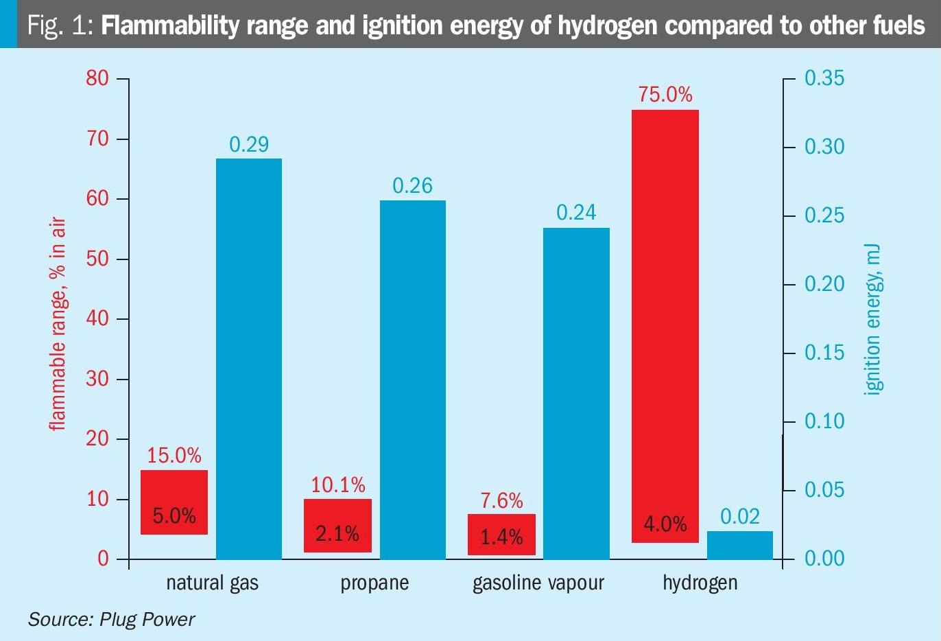
- increased risk of explosion (or detonation) as the rate of flame propagation for a combustible gas generally increases with the partial pressure of hydrogen in the gas;
- increased risk of high-temperature hydrogen attack (HTHA) as mapped by the Nelson curve.
Fig. 1 shows the flammability range and ignition energy of hydrogen compared to other fuels.
A third safety aspect that should also be borne in mind is the risk of attaining unexpected, explosive conditions during abnormal operation due to the targeted increase of hydrogen partial pressure during normal operation. Incomplete purging in connection with equipment inspection or venting of hydrogen-containing gas at an unsafe location can create conditions where explosive mixtures of oxygen and hydrogen could be formed. The risk of attaining explosive conditions is naturally higher in the process sections with high hydrogen concentrations.
There are, of course, other safety aspects to be considered as well however, not all of them are negative. In cases where the increased hydrogen partial pressure has been attained at the expense of a reduced CO partial pressure, there may in fact, be certain safety aspects that are improved, for example, lower risk of personnel poisoning by CO or carbonyls.
Hazards related to green ammonia processes
Production of ammonia by reacting hydrogen with nitrogen is not a new concept and hence does not require any specific analysis to identify hazards related to green ammonia production. On the contrary, there are certain operational and safety benefits to introducing pure hydrogen rather than producing it through the normal reforming process. There are however certain new safety aspects associated with the hydrogen production by electrolysis and novel aspects also result if there is an aim to vary the load of the ammonia plant as a function of power price as such dynamic green ammonia processes typically are controlled in a different manner than traditional processes. The safety aspects related to such novelties should of course also be considered.
Within the context of analysing novel risks related to green ammonia production, the most pertinent safety aspects to be discussed in the following sections can hence be divided into:
- safety aspects related to revised design result from requirements of enhanced process dynamics or other new design requirements;
- safety aspects related to green ammonia revamps – i.e. sending hydrogen as supplementary feedstock to an already existing ammonia plant and;
- safety aspects related to the production of hydrogen by electrolysis.
Safety aspects related to process dynamics
Efforts to optimise plant performance towards purely green operation typically lead to changes in process control1 and/or reactor design2, 3. Implications of such novel concepts on the plant safety should, of course, be carefully considered and addressed. These considerations will typically be made on a case-to-case basis and will, therefore, not be discussed further here.
Safety aspects related to green ammonia revamps
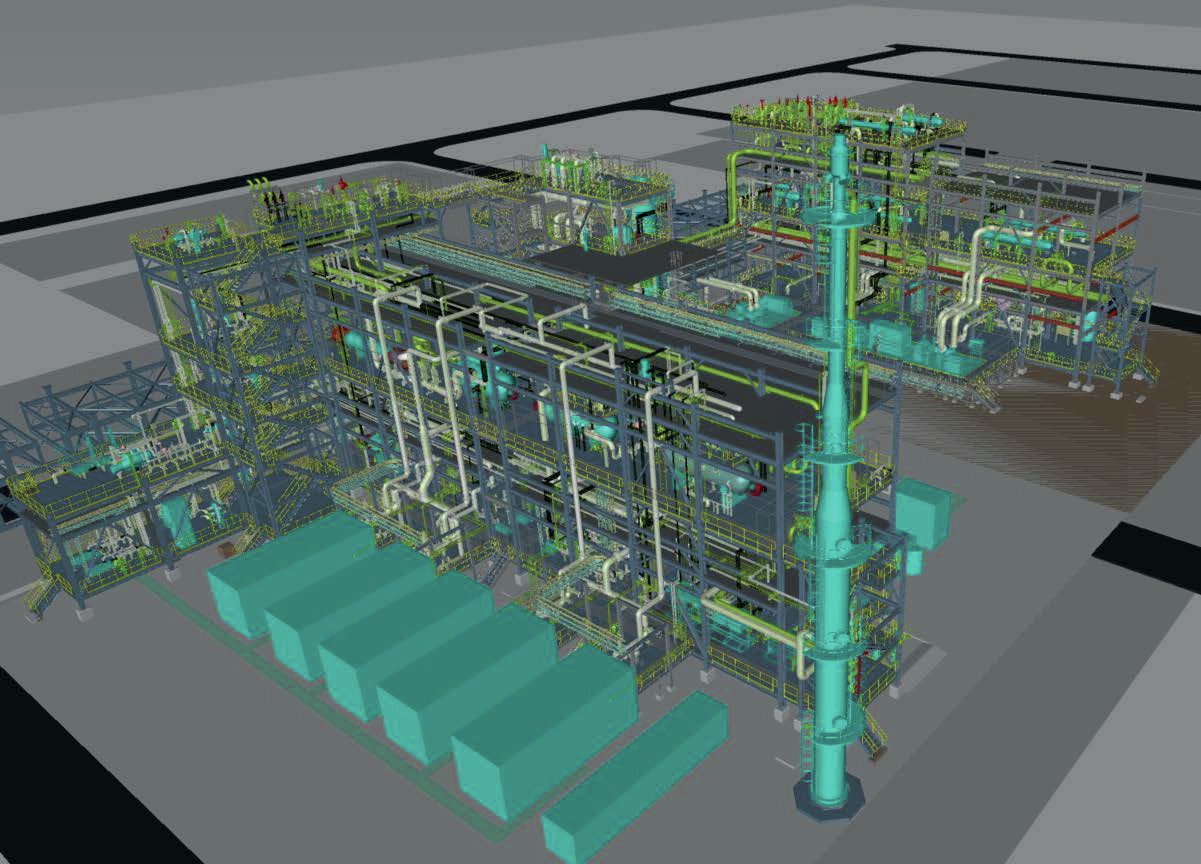
Most commercial-scale ammonia processes where a green revamp would be an option4 have an overall process configuration as shown in Fig. 2. Various versions of this generic process configuration exist5.
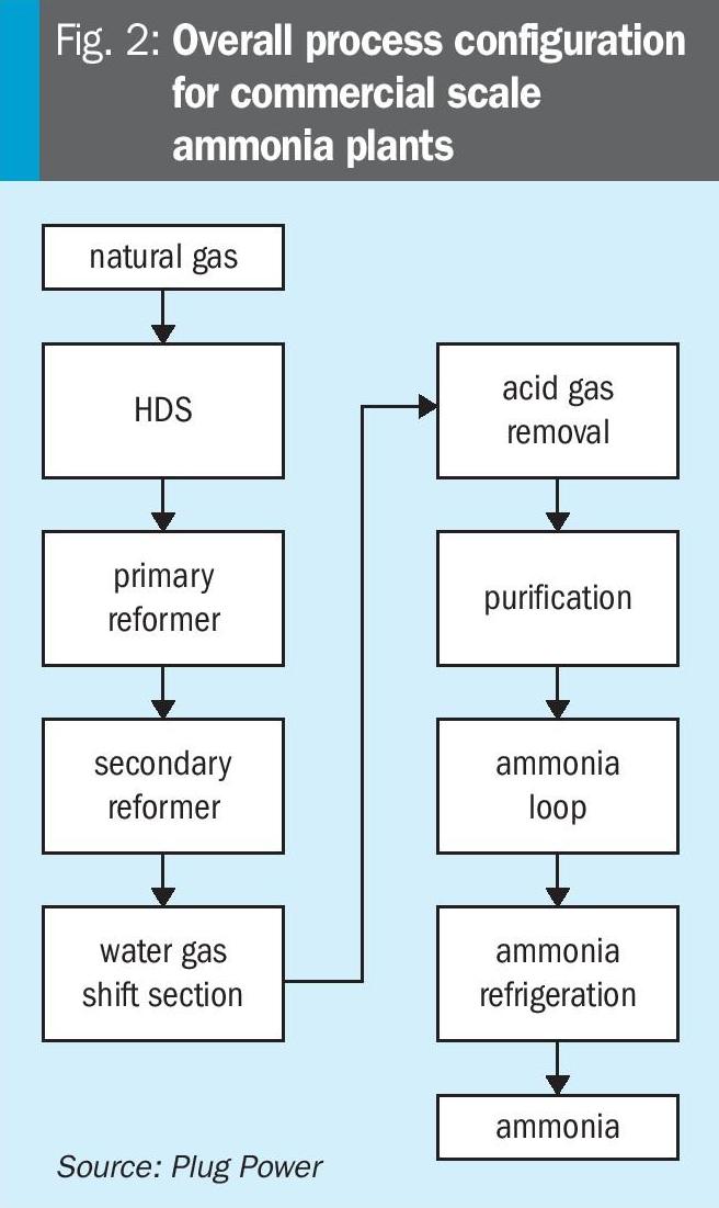
KBR developed a concept where the syngas purification takes place before introduction to the synloop in a so-called Purifier™. This adjusts the N2/H2-ratio in the syngas and thereby enables the reduction of the steam reformer size6. Others have discussed in some detail the implications of adding hydrogen to a conventional process based on two-step reforming7.
Implications of adding hydrogen to a traditional two-step ammonia process
Adding hydrogen to an existing ammonia plant naturally means that the ratio between reactants (H2/N2) is increased above the optimal value, and some other design or operational change is required to restore that balance. The obvious way to achieve that in a traditional two-step ammonia process is to shift the load from the primary reformer to the secondary reformer. Increasing the load in the secondary reformer means that a more significant fraction of the hydrogen and CO in the syngas is burned, and at the same time, the amount of nitrogen added to the syngas is increased. For small disturbances (up to say 5-7% excess hydrogen) there hence exists a certain shift in load, which will restore the balance between H2 and N2 to the desired value.
There are certain intrinsic safety considerations that must be made in connection with such a change in plant operation. In the first place, the temperature rise across the secondary reformer increases. This is a safety concern, and it will typically require that the inlet temperature to the secondary reformer is lowered so that the exit temperature from the secondary reformer does not exceed the mechanical design temperature of its outlet system. Excessive reduction in the primary reformer load, however, reduces the overall steam production from the unit. Hence, an appropriate balance has to be found, which both secures sufficient steam generation and avoids excessive temperatures exiting the secondary reformer. Addressing these issues simultaneously typically defines the limit for how much (green) hydrogen can be added to the plant and, hence, how much the plant capacity can be boosted if there is capacity available in downstream units.
An important implication of the above-mentioned modifications is that the process air compressor (PAC) will operate at an increased load. For plants where this is impossible, an alternative to increasing capacity is to add oxygen co-produced in the electrolyser unit, which produces green hydrogen for the unit and sends it to the PAC. Thereby, the load can be shifted from the primary reformer to the secondary reformer without increasing the load on the PAC, but such a change requires verification that the increased oxygen partial pressure in the PAC is acceptable from a design and safety perspective. Adding oxygen to the PAC could be attractive for plants where the primary reformer is the bottleneck or for feedstock-constrained plants. The overall result of such a modification is not an increase in production but merely a partial shift from grey to green production. At green ammonia prices8 of ~700 $/t and projected prices9 for 2030 exceeding 1,100 $/t, such modification could be quite attractive for many plants. Importing nitrogen to the process is another way to reestablish the stoichiometric ratio and can in principle be used to the extent required as long as there is still capacity available for compression to loop conditions.
Implications of adding hydrogen to a Purifier™ based ammonia process
At first glance, adding hydrogen to an ammonia plant with a purifier seems to entail less plant modifications than what was presented above. Maintaining process conditions (pressure and temperature) in the purifier will, in principle, ensure that the desired H2/N2 ratio is maintained even if the inlet stream to the purifier has an increased hydrogen content. This mode of operation requires that hydrogen is added upstream of the purifier and hence entails the safety implications related to an increase in hydrogen partial pressure as described previously. An alternative modification is to operate the purifier at a slightly elevated temperature, evaporating more nitrogen into the process stream and then adding the hydrogen downstream of the purifier. Both cases have to account for potential bottlenecks on liquid nitrogen supply and evaporation capacity in the purifier but adding hydrogen downstream the purified naturally increases the requirement for the purity of the hydrogen imported. A detailed analysis must be conducted on a case-to-case basis to determine the best configuration. Overall, the safety precautions related to adding green hydrogen to a purifier-based ammonia process seem relatively minor.
Hazards related to hydrogen production by electrolysis
The previous section addressed the implications of feeding pure hydrogen to the ammonia process. This section focuses on the safety aspects of the electrolysis unit itself.
There are several types of electrolysis units commercially available, but the dominating technologies can be grouped as:
- PEM (Proton Exchange Membrane)
- AWE (Alkaline Water Electrolysis)
- SOEC (Solid Oxide Electrolysis Cells).
Of these, only PEM and AWE are available on a large scale to enable commercial-scale ammonia production.
While certain of the safety aspects are different for the different technologies, there are also many safety aspects that are similar10. To facilitate an in-depth analysis of these, a thorough analysis will be made on PEM technology as offered by Plug Power – simply because this is the electrolysis technology for which the author has the best insight. Most, if not all, of the safety aspects discussed below are equally relevant for all types of electrolysis but there are, on the other hand, certain risks associated with the SOEC and AWE technologies which must be taken into consideration and are not covered here as such risks don’t exist in the case of PEM. For SOEC, such considerations relate particularly to the safety aspects of producing pure hydrogen in partially ceramic structures being heated up to 750-800°C (1,400-1,500°F) while in the case of AWE, the high concentrations and amounts of KOH in AWE systems demand additional safety measures.
The predominant risk associated with electrolysis is that a partition separating the anode side (with a high concentration of oxygen) from the cathode side (with a high concentration of hydrogen) ruptures and creates an explosive mixture of hydrogen and oxygen. This risk is intrinsic in all types of electrolysis technologies. There is a huge pressure on the development of electrolysis technology to reduce power consumption and make the technology more compact. The way to increase efficiency is to reduce the electrical and molecular resistance of the membrane or diaphragm between the anode and cathode sides by applying thinner membranes or diaphragms, but this naturally also leads to an increased risk of uncontrolled migration of hydrogen to the oxygen side or vice versa. Similarly, the push towards more compact layouts leads to geometries where oxygen and hydrogen in high concentrations are present in locations very close to each other.
This scenario and how to rectify its associated dangers will be the main focus of the subsequent part of this section. The analysis is relevant for all electrolysis manufacturers, irrespective of the type of technology.
There are essentially three types of pressure configurations available on the market:
- atmospheric electrolysis;
- pressurised alkaline electrolysis;
- PEM configurations with a pressure gradient across the membrane.
Plug Power’s configuration is of the latter type, where the anode side operates close to atmospheric conditions while the cathode side operates at 40 bar g (580 psig).
Safe design of PEM units
The process used by Plug Power to produce hydrogen by PEM is shown conceptually in Fig. 3. The stack (marked electrolyser on the sketch) is the core of the process where water is split into hydrogen and oxygen. Protons formed within the stack permeate to the downstream cathode side of the stack, where they recombine with electrons to form a mixture of hydrogen and water, which is then separated into its constituents in the downstream hydrogen high-pressure separator. Hydroxyl ions, conversely, are constrained to the upstream anode side where they donate electrons to the stack and recombine to oxygen and water separated in the oxygen separator. The anode side operates at close to atmospheric conditions, whereas the cathode side operates at a pressure exceeding 40 bar g (580 psig). Water is recovered from the cathode side and recycled to the anode side via the water recycle system (WRS), which reduces the amount of hydrogen transferred to the anode side. The process configuration indicated in Fig. 3 has many benefits from a safety point of view, as described below.
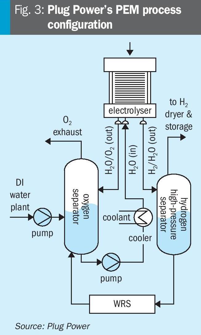
In the first place, the fact that the cathode side is operating at a much higher pressure than the anode side eliminates the risk that oxygen in relevant quantities should flow to the cathode side. This eliminates ~50% of the risk scenarios during normal operation (during which only the anode system can attain a flammable composition) whereas both the anode and cathode systems could achieve explosive conditions if both were operating at the same pressure. The high pressure on the cathode side is generated electrochemically, i.e. without any use of compression, so any safety aspects related to compression of hydrogen up to the supply pressure are also avoided.
Moreover, the worst-case explosive scenario is now governed by the maximum operating pressure of the low-pressure side (i.e. the slight overpressure at the anode side) instead of the hydrogen supply pressure, which governs the max pressure of an explosive mixture in a system with a balanced pressurised configuration.
Hydrogen, in small concentrations, will always be present in the oxygen section. There are two main mechanisms for hydrogen to end up in the oxygen section: hydrogen carryunder and hydrogen crossover.
Carryunder is the transport of hydrogen dissolved in return water from the cathode separator to the anode separator. Crossover is hydrogen diffusion from the high-pressure cathode side through the proton exchange membrane to the low-pressure oxygen side. These mechanisms are well understood and accepted.
Plug ELX systems are equipped with safeguards that shut down the system to a safe state when elevated hydrogen concentrations are measured in oxygen or when elevated oxygen concentrations are measured in the hydrogen. These safeguards are adequate if the concentration changes are slow and take five minutes or more. However, if concentration changes are faster than five minutes, a potentially dangerous gas composition can be created before the safeguards can detect the condition. This potential safety issue has been addressed in Plug Power’s design as described below.
The most common failure mode for a PEM electrolyser is the development of a pinhole leak between the cathode and anode compartments. These leaks do not pose a risk since they can be detected in time, and the system can be shut down safely. In very rare cases, a membrane can rupture, forming a much larger hole. Though very rare, it must be considered.
Since the hole size of a pinhole or even a larger rupture is impossible to quantify, Plug Power assumes for the design of the safety system the worst-case situation that a rare crossover event can cause a hydrogen-oxygen mixture to occur in the oxygen-water separator that will explode.
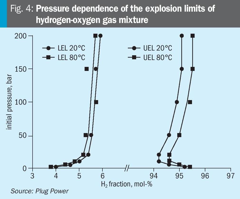
For hydrogen and oxygen gas mixtures, the explosive limit range is very wide and gets wider as the temperature increases. The lower flammability limit (LEL) of hydrogen in oxygen is 4 vol-% at 20°C (45°F) and 1 bara (14.5 psia), while the upper flammability limit (UEL) is 95.2 vol-%. Measured LEL and UEL values for hydrogen-oxygen mixtures as a function of temperature and pressure have been measured by others11. The results are shown in Fig. 4.
Between the LEL and the UEL the gas mixture is flammable, and an ignition may result in a deflagration or detonation. Deflagration propagates with the velocity below the speed of sound (sub-sonic) in the unburned mixture. A detonation propagates with the velocity above the speed of sound (super-sonic).
Deflagration events in enclosures or confined spaces lead to significant overpressures. The pressure peak is nearly ten times higher than the initial pressure in oxygen-hydrogen mixtures. During deflagration, the pressure grows almost uniformly within the enclosed space. Deflagration in an enclosure can be mitigated by venting. This is the most cost-effective and wide-spread explosion mitigation technique.
Detonation is the worst-case scenario for a hydrogen incident. Detonation propagates 2-3 orders of magnitude faster than deflagration, resulting in pressures at the detonation front more than 15-20 times higher than the initial pressure. The venting technique used to mitigate deflagration events does not apply to detonation events, as there is insufficient time to release the pressure. Where deflagration events produce a uniform increase in pressure inside a closed vessel, detonations tend to show an oscillatory pressure response where very high but short pressure peaks are produced.
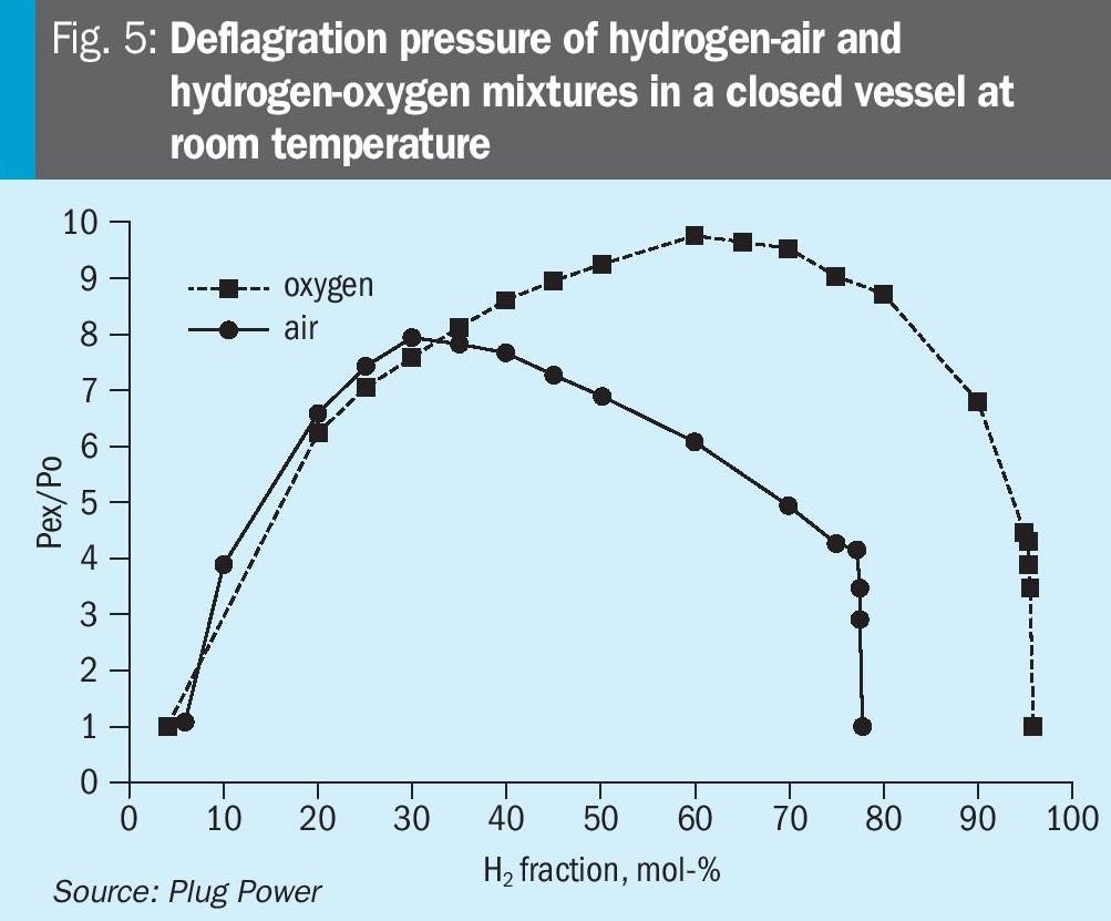
For hydrogen-air and hydrogen-oxygen mixtures, the highest deflagration pressure peak is obtained at a stoichiometric composition – see Fig. 5. The pressure behaviour of detonations looks similar but with much higher and shorter pressure peaks. Consequently, the worst-case scenario for a hydrogen-oxygen explosion is at a stoichiometric composition of 66.6 vol-%hydrogen and 33.3 vol-% oxygen.
Attaining ExPSR certification through experiments
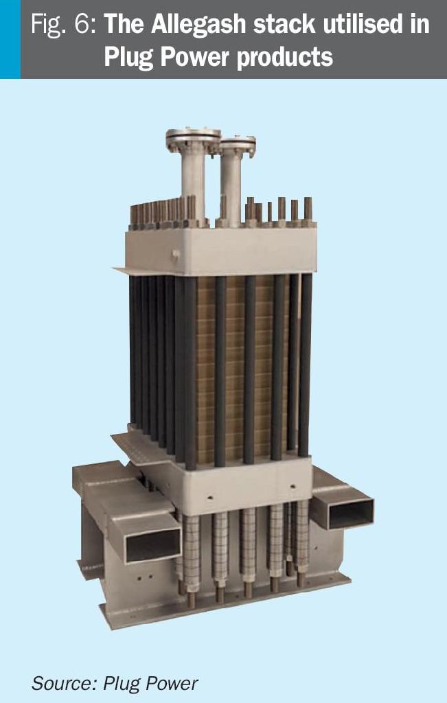
The safe operating limits were determined experimentally to be sure that the oxygen-water separators could handle a stoichiometric detonation. Currently, Plug Power supplies two different size electrolyser systems: a 5 and a 10 MW system. These systems use oxygen-water separators of various sizes, and consequently, these need to be explosion tested separately. All systems use the Allagash stack depicted on Fig. 6 for the electrolysis process. The pressure vessels and the Allagash stack have been subjected to explosion testing based on European norm NEN-EN 14460:2018 for explosion pressure shock-resistant equipment where permanent deformation is allowed.
NEN-EN 14460 specifies requirements for explosion-resistant equipment that will withstand an internal explosion without rupturing and not give rise to hazardous effects on the surroundings. It applies to equipment (vessels and systems) where explosions are an exceptional load case. There are two types of explosion-resistant equipment: explosion pressure resistant and explosion pressure shock resistant. Explosion pressure-resistant equipment is designed to withstand the explosion pressure without permanent deformation and will not harm the surroundings. For explosion pressure shock-resistant equipment, permanent deformation is allowed, provided the equipment will not give rise to hazardous impacts on the surroundings.
IBExU conducted the explosion tests in Freiberg, Germany. The IBExU Institut für Sicherheitstechnik GmbH, IBExU for short, is a technical engineering service company in the field of explosion protection with a tradition going back to 1928. IBExU is an accredited test laboratory and accredited certification centre for the testing/certification of equipment, protective systems and components intended for use in potentially explosive areas in addition to safety, control and control equipment for use inside of potentially explosive regions in accordance with Directive 2014/34/EU.
To assess the vessels in terms of explosion pressure shock resistance, static ignition tests with stoichiometric H2/O2 mixtures were performed at various initial pressures. The gas volume inside each vessel was flushed at least three times with the stoichiometric gas mixture and then pressurised to the desired test pressure. This gas volume in the vessels was then ignited.
The tests started at a low ignition pressure, and the pressure gradually increased after every successful test. A test was successful when only ductile failure was observed, and no significant pressure peaks appeared 1 m (3ft) from the vessel. The fact that the vessel could be pressurised for the next test is proof that the previous test did not compromise the vessel integrity. The highest initial vessel pressure where no failure was observed is called the safe explosion pressure (SEP).
In total, 21 experiments were performed. where the conditions were gradually worsened until point of rupture. Each test was initiated at ambient temperature – approximately 20°C. The measured maximum pressure peaks were at least 7.3 times the vessel’s design pressure and peaks up to 90 times the design pressure were observed. Because the duration of these high-pressure peaks is extremely short (in the order of several microseconds), the vessels can withstand these detonation events without brittle failure. When the test pressure was less than 52% of the design pressure of the vessel (absolute pressures), the vessel passed the test. Only when the test pressures exceeded 52% of the vessel’s design pressure, did the detonation cause not only permanent deformation but also the ejection of the full content of the vessel.
Explosion experiments with the electrolyser stack showed it has a better explosion shock resistance than the separator vessels. Based on these results, it was decided to operate at 65% of the safe explosion pressure of the vessels, with the pressure safety valves set at 75% of the safe explosion pressure. The Plug ELX systems are equipped with SIL safeguards to ensure operation within a safe window.
Conclusion
All electrolysis processes are inherently challenged by the fact that pure oxygen and hydrogen are co-produced in the process systems and typically only separated by a thin partition. The safety aspects of a potential rupture of this partition have to be considered. This paper hence also explains how a dedicated effort resulted in achieving extraordinary safety features without adding substantially to the cost of the electrolysis.
It is believed that the standards to which Plug Power has designed their system could leverage further development of good industrial practice within the space of green ammonia technology. They have certainly proved their worth in the dozens of plants Plug Power have delivered electrolysis equipment to until now.
References