Sulphur 389 Jul-Aug 2020
31 July 2020
Solving amine foaming problems
GAS PROCESSING
Solving amine foaming problems
Although amine solution foaming problems have been studied and reported extensively, direct correlations about the root causes of foaming have not been completely established. This article approaches the problems of foaming from a different perspective, rather than theoretical discussions, the topic is centred exclusively on Amine Experts’ field-related experiences with amine foaming episodes.
Amine solution foaming is a phenomenon that has been intensively studied and reported elsewhere. Several foaming root causes have been determined throughout the years, however, the latest experiments suggest that the predominant mechanism for foaming is related to contaminants in the form of surface-active materials, or surfactants. These contaminants can enter the unit in solid, liquid or gas phases and often modify the solution properties in such a way that foam (in gas contactors) and emulsions (in liquid-liquid treaters) is produced leading to a series of negative effects, predominantly hindering the process from meeting specifications and causing amine solution losses.
Foam is initiated when energy is imparted on the solvent, most commonly by means of agitation. The tendency for a foam to form is directly related to how much energy occurs at the surface of the solvent. In some cases, the foaming tendency correlates with the surface tension of the solvent. It is an inverse correlation, as the surface tension decreases, the foaming tendency increases. Amine solvents have been observed to have low foam tendencies as they have high surface tensions. Contaminants such as liquid hydrocarbons, or heat stable salts have low surface tensions, increasing the foaming tendency as they accumulate in concentration. These foam events can be short lived, and in many cases, go unnoticed as they may not affect the amine system in a significant way. While the foam is being created through energy, it is also being broken; its ability to maintain its form is known as foam stability. When surfactants and other compounds that change the interfacial rheology of the foam are present, there is not only an increase in foaming tendency but also an increase in foam stability. If this type of foaming occurs, it does not go unnoticed and several process changes may be observed, such as:
- differential pressure increases across the trays/packing in the contactor and/ or regenerator;
- decrease in contactor and/or regenerator bottoms liquid level, or more likely a closing of the absorber/regenerator level control valve to maintain the setpoint;
- temperature bulge position changes inside the contactor tower;
- increasing liquid level in the amine contactor outlet knockout drum, as amine solution is carried over with the treated gas (leading also to amine losses);
- increase in H2 S or CO2 levels in the treated gas (in the case of selective MDEA service, the CO2 levels in the treated gas may reduce, as a foaming MDEA picks up more CO2 );
- increased liquid level in the reflux drum;
- amine, hydrocarbon and surfactant contamination of the regenerator reflux water.
Foaming of the amine can often lead to carryover from the contactor or regenerator with the treated gas or acid gas, respectively. Most amine units have separation vessels after the contactor outlet to recover the carryover. In extreme cases, amine carryover may exceed the removal capabilities of the knockout drum and reach downstream systems such as dehydration units, mercaptan removal beds, mercury removal beds and others. Foaming in a regenerator is also detrimental as foaming amine will not regenerate. Furthermore, flooding of the reflux accumulator can result in carryover with the acid gas, which can reach the sulphur recovery units, flare systems, acid gas injection units or other downstream processes. In cases of CO2 -only processing, the carryover may manifest itself as amine spraying out a vent stack into the surrounding environment or process units.
Determining the source of foaming requires thorough investigation of several possible sources. Following is a list of some of the many contaminants and sources that have been determined to be the root cause of amine foaming:
- Ineffective inlet separation leading to contaminant ingress
– pipeline chemicals such as corrosion inhibitors, hydrate inhibitors, fracture fluid organic acids, dispersants, soap sticks
– liquids from pigging
– compressor lubrication oils
- Ingress of gas-phase contaminants carried with the feed gas (such as BTEX)
- Hydrocarbon condensation inside the contactor by not maintaining appropriate temperature differential between lean amine and inlet gas (or more accurately, the hydrocarbon dew point) when processing heavy hydrocarbon-rich feed gas
- Problems in the activated carbon bed
– incorrect type of activated carbon (exposed to phosphorous-based activation)
– spent activated carbon beds releasing contaminants into the outlet stream
- High concentration of suspended solids in the amine
- High soluble iron in the lean amine (resulting in fast/high solids formation in the contactor)
- Problems with the antifoam
– incorrect antifoam (some antifoams will cause foam)
– excess antifoam injection (excess anti-foam use can, in some cases, stabilise or induce foam)
- Contaminants present in the fresh amine and/or make-up water
- Incompatible filter media or materials of construction
- Cleaning chemicals not properly flushed before filling system with amine
Because amine foam is stabilised by contamination of one type or another, foaming can be eliminated or greatly reduced in severity and/or frequency if efficient inlet separation (filtration and coalescence) is in place upstream of the amine contactor. However, if the amine solution does become contaminated, a proper amine filtration system and activated carbon adsorption beds are helpful in removing the contaminants. Antifoam use is a common method to temporarily control the detrimental effects of foaming, however, the effectiveness of a given antifoam may be limited depending on the type of antifoam used and the location where it is injected. Some plants use antifoam on a regular basis, but this could harm the solution and plant in the long term.
Root cause analysis of foaming and the elimination of its source are the best ways to deal with a foaming amine solution. Nevertheless, antifoam may need to be required when sporadic foaming incidents occur, and the source of foaming agent has not yet been identified.
Plants should proceed with caution when adding antifoam to keep the unit under control, especially when operating at high production rates. The antifoam will usually separate as a top layer in the unit flash tank, sump or surge tank surface. It can also be removed by certain filters and carbon adsorption beds (for most types of antifoam), hence, their build-up in the circulating solution can be controlled. Typical antifoams used in amine service fall into the following categories: silicone-based, silicone esters, polyglycols, high molecular weight alcohols and polyalkyl ethoxylates. The correct antifoam for the system is best determined with onsite foam testing. However, silicone-based antifoams are perhaps the most effective products, but at the same time the least chemically compatible with amine solvents.
War stories from the foaming front
Field experiences in amine unit foaming, testing and troubleshooting are critical factors to better understand the foaming phenomenon, its origins and how to combat its effects. Foaming can be a tricky problem to solve, as it involves investigation into the chemical, operational and design aspects of the unit. The following case studies provide examples of how thorough, disciplined reviews of various foaming incidents resulted in mitigation of the foaming problems.
Case study 1
A Southern US gas processing plant rated for 200 million std ft3 /d, using activated MDEA, was shut down because the plant could not meet its H2 S specification well below rated capacity, because of severe foaming. Onsite work was performed to determine the root cause of the original foaming event, but it became an ongoing foaming study when the newly replaced solvent continued to show significant foaming and fouling, even with reduced gas flows entering the amine unit. The operators were perplexed, because the system had what would normally be considered a very good system preparation and filtration set up. The plant had a large slug catcher, a post-compression separator and a newly installed helical inlet filter/coalescer. There were particle filters and a carbon bed on the lean amine, as well as particle filters on the rich. Feed contaminants should have been reasonably removed, but if they did enter the system via inlet carryover, the in-system filtration should have been successful at cleaning up the amine.
Root causes
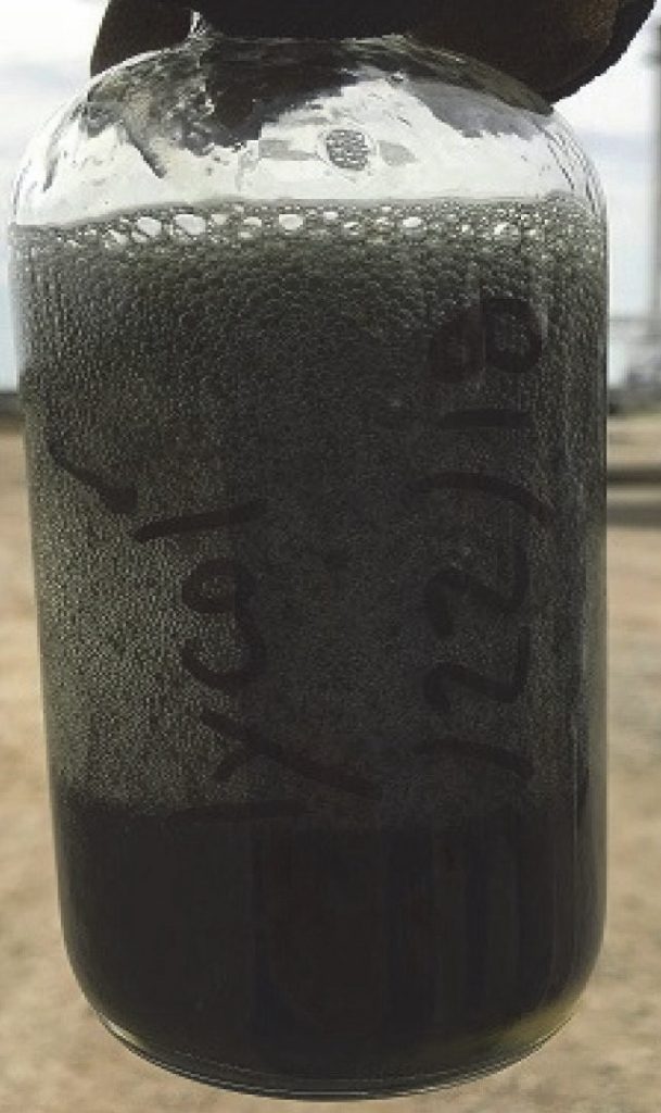
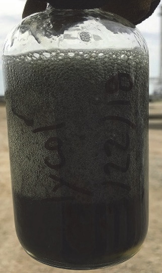
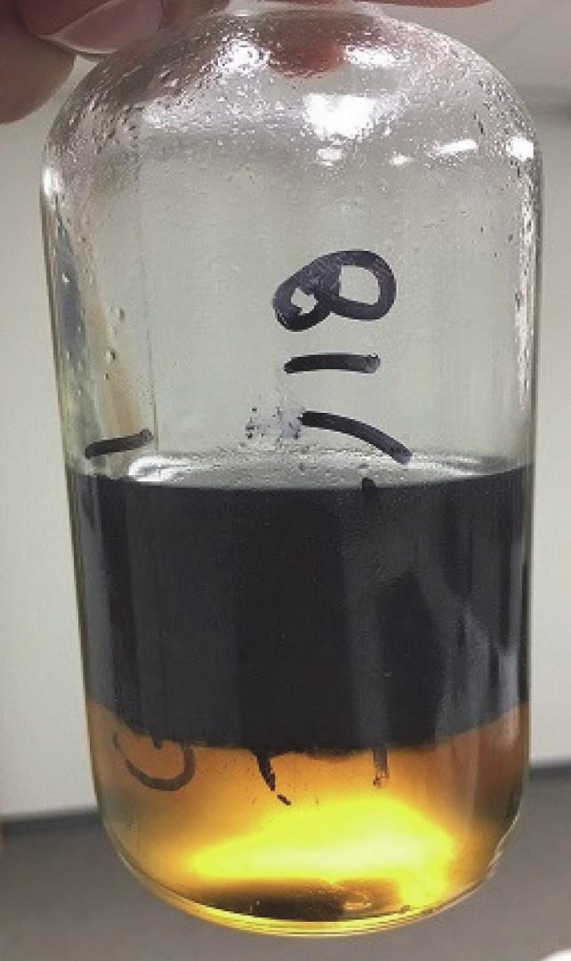
Solving the foaming problem was made more urgent when the downstream glycol dehydration system also showed signs of severe foaming (and fouling) when some of the feed gas entered the glycol unit without having first passed through the amine unit (low feed gas H2 S and CO2 composition meant some gas could bypass the amine unit, and when blended with the amine treated gas, would still meet pipeline specification). Not only did the glycol foam uncontrollably, similar to the amine, but the previously water-white glycol suddenly became black and viscous. Fig. 1 shows the foaming glycol after taking the sample and a day later after allowing phase separation. The solution looked remarkably like the amine prior to the shutdown.
It appeared that if gas rates were maximised to the facility, significant contamination of the process units was inevitable. The contaminant not only increased foam tendency and stability but also the fouling of the systems. The source had to be found immediately, or the entire plant would need to be shut in.
Tracing back from the inlet to the amine unit, and downstream of the helical separator, dark, black liquids were found in a low spot in the gas line. When introduced to both fresh amine and TEG, it increased the foam tendency and stability of the foam. Had the coalescer been working properly, this fluid should not have been in the gas line. Testing with a “gas super coalescer” test unit (GASCO test rig) showed that the new coalescer was only separating at 77% efficiency, well below its rated efficiency of 99.9% of solids down to 0.3 micron and 99.5% of liquids 0.3 micron and larger. Optimisation of this coalescer was left to the manufacturer.
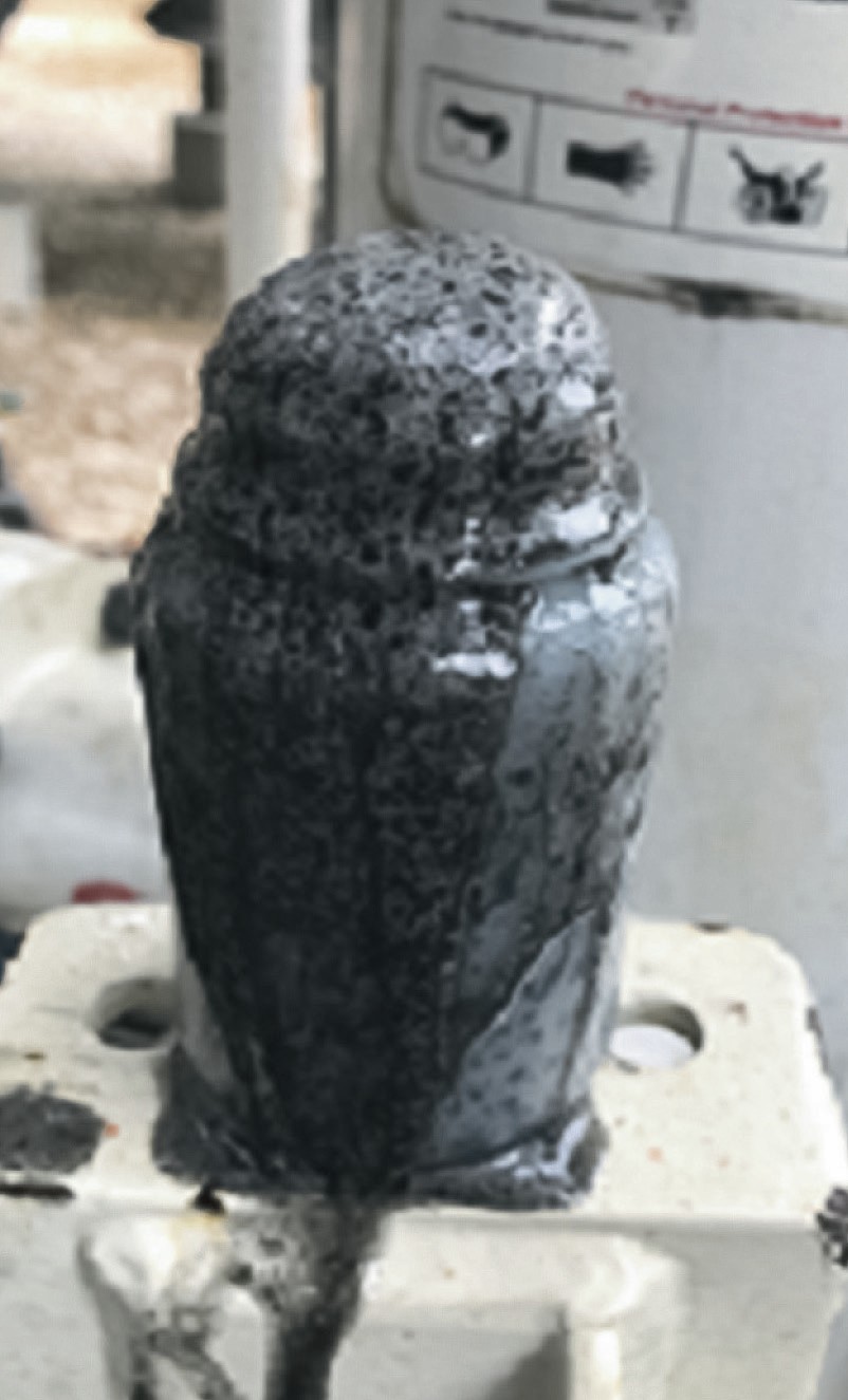
Sampling further back to the large inlet horizontal separator, what looked like an eruption of foaming grey fluids was found filling the lower half of the knockout drum. Fig. 2 shows the foaming inlet separator fluids, which were being swept downstream of the knockout KO) drum at maximum gas rate conditions.
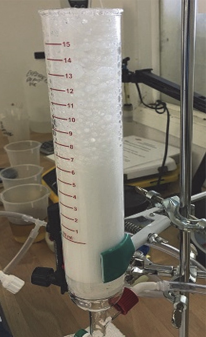
Discussion with operations staff indicated the inlet separator had level control issues after a new black powder (pipeline cleaning product) solvent was injected upstream of the plant feed gas header. A sample of the solvent was added to fresh amine and caused the solution to foam right out of the test frit. Fig. 3 shows the results of the foam test.
The new pipeline flow control solvent was indeed the cause of the bad plant foaming and fouling. It was surmised that at lower gas rates, the inlet separation devices didn’t entrain as much of the foam/froth from the inlet knock-out, and any material that did pass through was primarily removed by the new coalescer.
However, at high gas rates, excess froth was swept out of the knock-out and through the poorly performing coalescer and into the amine and glycol systems. The product’s high surfactant properties increased the foaming in the systems, and its solid removal properties cleaned any residual solids off the vessel walls and piping in both the amine and glycol systems, leading to the elevated solids loads in the systems.
The major foam event was solved, and plans put in place to discontinue the high solvent injection rates and install a more effective element-based filter/coalescer downstream of the helical unit. The amine and glycol solvents were replaced after cleaning the units and circulated with clean, dry sales gas flow to prevent precontamination of the system before the new separation device was installed.
Unexpectedly, the amine solution continued to foam quite severely even with clean gas and new solvent.
This problem required further technical support to solve. A gamma scan was performed on the contactor, showing that the foaming was taking place at the top of the tower. This was the first indication that foaming was likely being caused because of the foam tendency exhibited by the lean amine solution. If the foaming occurred at the bottom sections of the contactor, it would suggest that the feed gas had the foam promoting contaminants. Testing of the make-up water and fresh amine in storage (diluted with distilled water), showed no foam formation. Both factors were discarded as the foam root cause.
The carbon bed should have been able to clean up any foam promoting residuals in the system. However, it appeared to be ineffective. Samples of the amine entering and exiting the carbon bed both showed foaming. Evaluation of the carbon indicated that it was an inferior product for the application and it was replaced with a material having the correct pore distribution for the type of contaminants that are typically found in amine systems. There were definitely shortfalls in the carbon adsorption bed, but why the elevated foaming tendency with clean amine in a clean system? That required further evaluation.
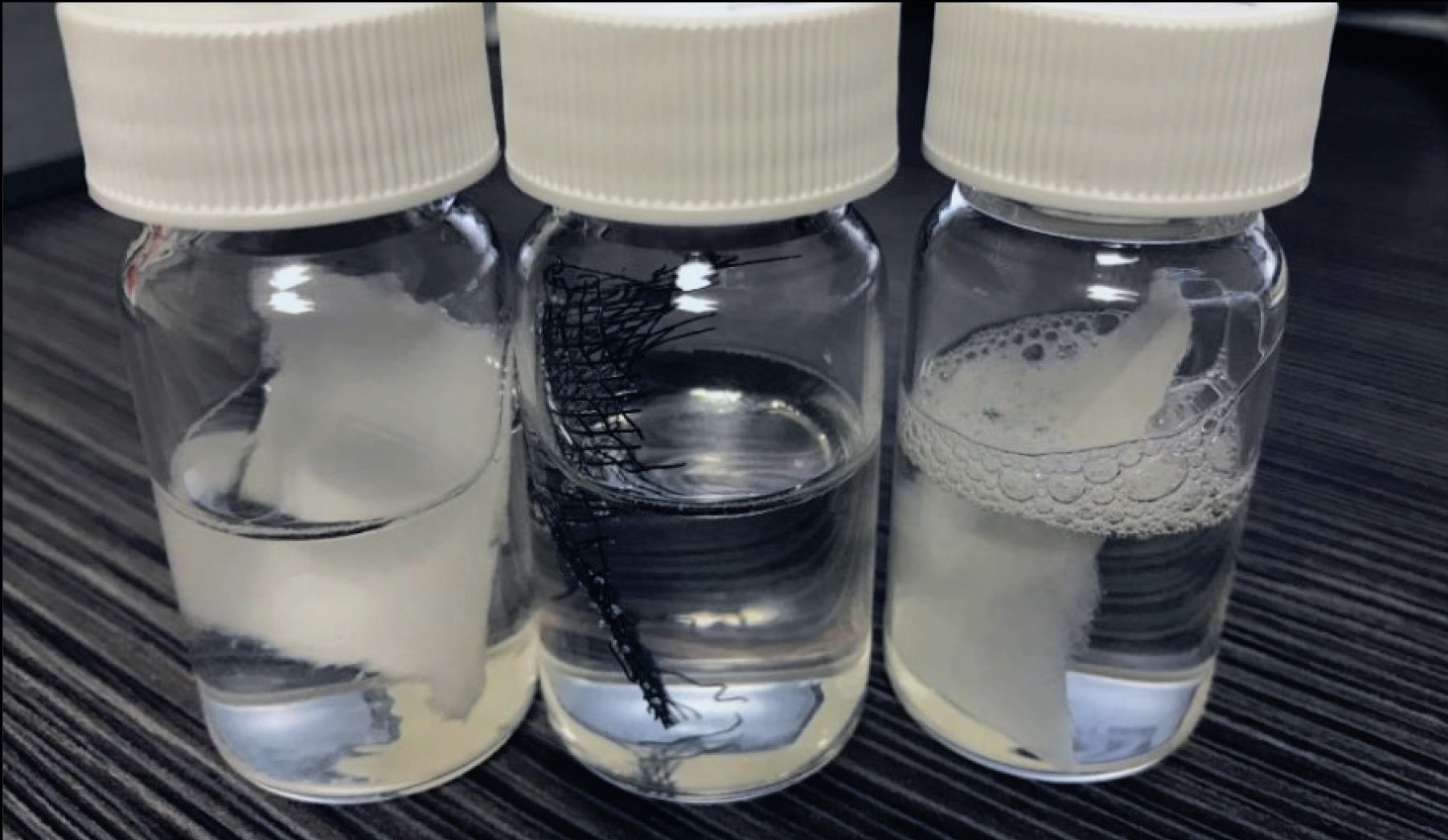
The pleated-style rich amine filters used yellow cellulose as the filter media. The materials in the filter (filter media, screens, adhesive), showed good chemical compatibility with the amine solution after testing and did not contribute to appreciable foam stabilisation. Attention was then turned to the lean amine filters, which were located between the regenerator and the lean/ rich exchanger. The harsh chemical environment combined with the high temperatures in this location significantly limits the materials compatibility and the possible options for filtration. Fig. 4 shows a simple chemical compatibility test, foam formation and stabilisation with 50% activated MDEA solvent taken from the fresh amine storage tank. A test soak conducted on all material components in the filter element indicated that the white cellulose filter media was causing severe foam stabilisation. Foam was stable up to two hours after a few minutes contact with the amine solvent. The test was conducted at ambient temperature. Therefore, at the much higher regenerator outlet temperature, it is expected that the effect is exacerbated.
The fact that the yellow cellulose (rich filters) did not cause amine solution foaming but the white cellulose (lean filters) did, called for a more in-depth investigation. After a review of the available information, it was determined that the yellow cellulose is impregnated with a phenolic resin that is amine compatible, whereas the white cellulose is impregnated with polyesters and other amine incompatible components. The impregnation process is used to impart mechanical resistance to the cellulose material. The adhesive in the filter element was not tested and became irrelevant as the media was much more important in comparison.
It is important to know that some cellulose materials should not be used in amine units. Only properly specified cellulose filter media, with correct compatibility properties, will function in amine units properly and not cause any foaming.
There are several aspects to consider in materials compatibility in an amine unit. Some of these can promote foaming and some affect the process negatively but not necessarily cause foam. The key aspects in materials compatibility in an amine unit are outlined below:
- Chemical degradation of filter materials. Leaching residues released from the filter material can be foam promoters.
- Media erosion and distortion (physical changes, not necessarily associated directly with foaming, but reduce the particle-removal efficiency of the filter, which can then lead to increased foam stability)
- Filter media fibre release (can also lead to foam stabilisation)
- Thermal compatibility related to melting or softening of filter materials. High temperatures can compromise certain filter materials enhancing also any possible chemical degradation.
- Mechanical compatibility related to the tensile strength of the filter material at the actual process conditions.
Chemical incompatibility is perhaps the leading cause of materials compatibility leading to amine foaming. An example of such a situation is the use of polyester filter media in an amine unit process. Polyester will suffer a chemical reaction with amine solution, essentially causing the fibre to dissolve, leading to an eventual filter media damage, rupture and by-pass. It can also often promote foaming.
Conclusions
Solving foaming in the short and long term at this plant was challenging and required a multi-pronged approach. Improving inlet liquids removal, better materials compatibility and ceasing injection of foam promoting chemicals at the plant inlet. The plant was required to install a high efficiency gas coalesce downstream of the helical coalescer. This improved liquids removal efficiency at the inlet of the unit and ensured minimal contaminant ingression. The plant also optimised its antifoam program using a more efficient antifoam, which was determined through proper laboratory testing of several different products. The lean amine filter media was changed from a chemically incompatible cellulose to cotton; in addition, the filter O-ring elastomers were switched from Viton to EPDM (best compatible material with amine solutions).
Finally, the plant ceased the injection of the black powder solvent into the feed gas at the inlet of the plant. The combination of these items alleviated considerably the foaming incidents in the amine unit and any further foam incidents were controlled much more effectively.
Case study 2
A large gas plant (using Diglycolamine, DGA® ) experienced almost continuously high absorber differential pressure readings and bottoms level control problems during the winter months (the effect was not as pronounced in the summer). Unless antifoam was continuously injected in the winter time, the contactor level controller would close flow, causing the flash tank level controller to close flow and ultimately starving the regenerator of amine solvent.
This plant had excellent inlet gas separation and coalescing filtration. The amine was also very clean and had an appropriate filtration process. The amine was maintained at a temperature of 5°C warmer than the inlet gas, other than the summer months when the ambient temperature prevented adequate cooling of the amine and the differential temperature increased to approximately 15°C. Foam testing of both the lean and rich amine revealed very low foaming tendency and stability levels.
This plant was brand new, clean, well-operated and showed no signs of contamination. So, what was the problem?
Root causes
The root cause of this foaming problem was related to the condensation of hydrocarbons within the absorber.
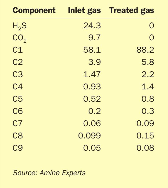
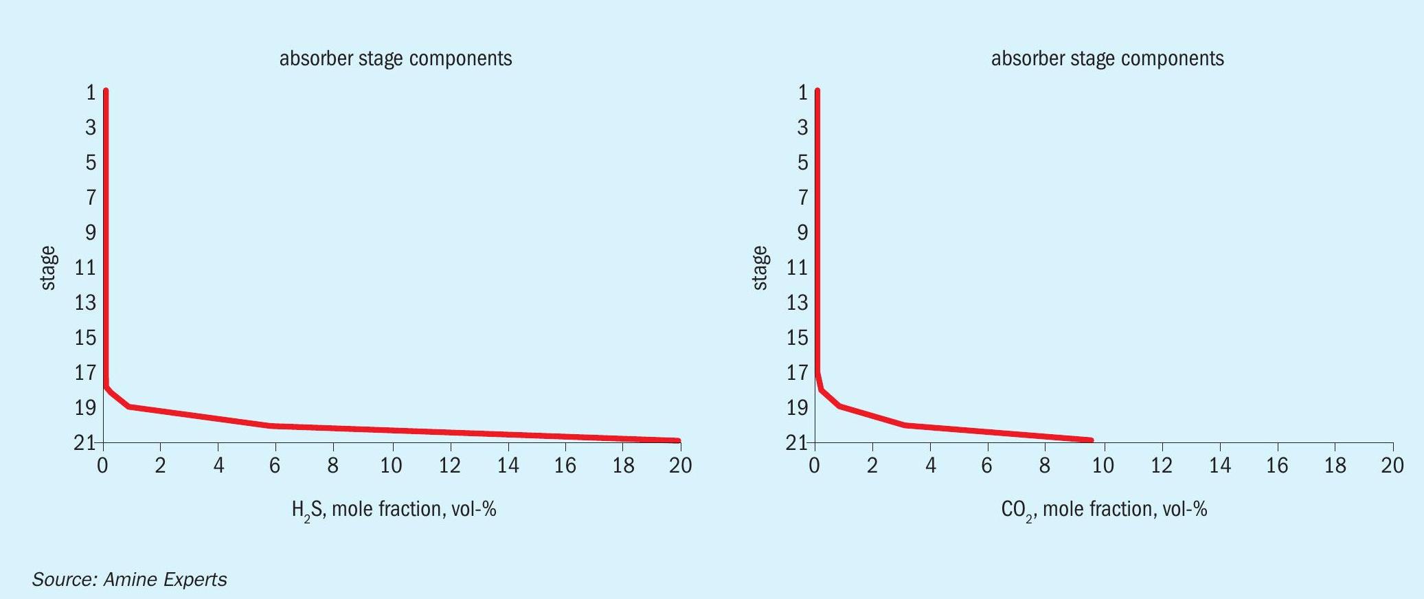
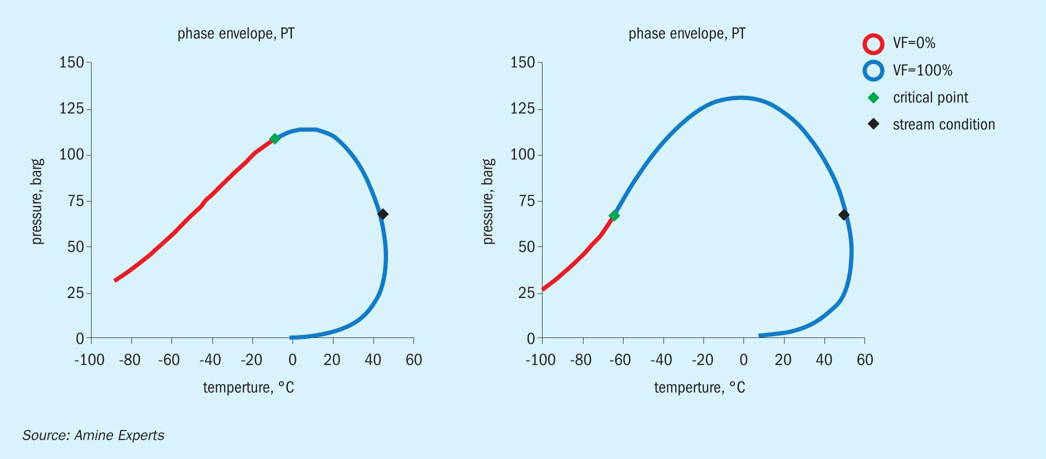
Table 1 lists the acid gas and hydrocarbon composition of the inlet and outlet gas streams of the absorber.
Because the large volume of H2 S and CO2 being removed by the DGA resulted in a concentration of the remaining hydrocarbons, the hydrocarbon dew point was dramatically shifted as the gas bubbled up through the trays. Fig. 5 shows the H2 S and CO2 removal profile, and Fig. 6 shows the inlet/treated gas hydrocarbon dew point phase envelopes.
As shown in Fig. 6, the hydrocarbon dew point in the inlet gas (at the absorber pressure) was 42°C, whereas in the treated gas it was 50°C, which was exactly the same as the set point of the lean amine. In the summer months the amine could not be cooled to the set point, instead it operated at temperatures of 55°C-60°C, which was above the hydrocarbon dew point. It was in the winter time, when ambient conditions allowed for better amine cooling, that the hydrocarbon dew point line was crossed.
When the dew point of the treated gas matches the lean amine temperature, it is almost certain that hydrocarbons have been condensed inside the absorber, and therefore, these components do not appear in the treated gas analysis; they were liquefied and do not exit with the treated gas.
Because the DGA was so powerful at removing the acid gas components from the inlet gas, the gas was “sweet” after passing through only the bottom three trays of the absorber. Once there was no more exothermic reaction occurring, the gas simply cooled to the same temperature as the lean DGA, which was 50°C. This cooling happened by tray 5 from the bottom, which is where the foaming would have originated. The first symptom operators noticed was an increase in differential pressure, followed roughly two minutes later by a closing of the absorber level control valve. The reason for the delay in the valve closing was it takes roughly two minutes for the bottom couple of trays to drain once the foaming amine above stops flowing downward. Because the inlet gas is now contacting dry trays, the temperature bulge shifts upwards, as does the foam and, if antifoam was not added, eventually there would have been H2 S breakthrough, and amine carryover. Because of the lack of rich amine flow the operators added antifoam long before this ever occurred.
Solutions and mitigations
Because of the large volume of acid gas removed, which greatly shifted the hydrocarbon dew point, the typical “rule of thumb” to keep the lean amine 5°C warmer than the inlet gas temperature was not adequate. In this case, the required differential temperature between the lean amine and inlet gas was closer to 15°C (which the plant was doing in the summer months). This adjustment was made, and antifoam is no longer required at this facility, although the operators keep it on hand.
In most amine systems, this level of differential temperature would put the plant at high risk of going off specification on H2 S (because hot absorbers do a poor job of H2 S removal). Luckily, a combination of very high H2 S and CO2 partial pressures in this absorber and the usage of a primary amine such as DGA allowed this facility to remain operating within required parameters and specifications, even at higher temperatures.
Conclusions
The so called “rules of thumb” should not be used to determine operating setpoints in amine units. What works for five units in a row may not work for the sixth unit. For lean amine temperature, it should be set as low as possible but still above the treated gas hydrocarbon dew point.
Final remarks
One of the most important lessons learned over many years of work in various amine units and solving foaming problems globally is that there can be a multitude of factors causing an amine unit to experience foam. Only in some cases is there a single factor as the main cause leading to foaming: often there are several items contributing to foaming. Perhaps one of the most important factors in foam promotion are inlet contaminants, so contamination control at the unit entry is a critical step for ensuring minimal foaming episodes.
The majority of the plants that do not consider this step often fight against foaming in addition to high operating costs, low reliability of equipment, and many other adverse incidents with economic and environmental impacts. Other sources of foaming should also be considered, such as operational practices and of the materials being used within each piece of the amine plant equipment. Sometimes the culprits can be found where one least expects. Therefore, a comprehensive testing plan, with systematic analysis protocol, should always be performed, not only to determine the cause(s) of foaming but also to form a plan for effective, long term foaming mitigation.
Acknowledgement
This article is an abridged version of the paper “War stories from the foaming front” by Dr David B. Engel of Nexo Solutions, Ben Spooner, Steven Ayres and Michael Sheilan of Sulphur Experts/Amine Experts. Four further case studies are presented in the full paper.