Nitrogen+Syngas 367 Sept-Oct 2020

30 September 2020
Lowering CO2 emissions with EARTH® technology
STEAM REFORMING
Lowering CO2 emissions with EARTH® technology
TechnipFMC’s EARTH ® technology, with its structured catalyst jointly developed by TechnipFMC and Clariant, has been proven to be a cost effective way to drastically improve productivity and energy efficiency of the steam reforming process, while reducing the CO 2 footprint per unit hydrogen and syngas product. The technology can be applied in projects to increase the capacity of ammonia and methanol plants and allows significant reduction of greenhouse gas emissions. S. Walspurger of Technip Benelux B.V. and S. Gebert of Clariant GmbH report on the EARTH ® technology and its applications.
Syngas and hydrogen are the most widely used industrial gases in the bulk chemical, refining and petrochemical industries. Syngas is an essential primary building block to produce ammonia, methanol, oxo alcohols and synthetic fuels via Fischer Tropsch synthesis. Nearly half of global hydrogen generation is used to produce ammonia, which is then used either directly or indirectly as fertilizer (>75%) and as a building block in the chemical industry. Another significant share of the hydrogen generation finds application in the refining sector, for clean upgraded fuels production.
With increasing worldwide population, and increasing demand from the agricultural and chemical sectors, worldwide ammonia production capacity continues to grow. However, market overcapacity combined with a strong trend towards higher efficiency application of fertilizers (e.g. via digitalisation), currently limits capacity growth to a relative low level (approx. 1% p.a.). Furthermore, persistently low ammonia prices put considerable pressure on producers’ margins.
In refining, hydrogen consumption increases as the requirements for upgrade of fuel quality drives the demand for deeper hydrotreatment and hydrocracking processes. In addition, the recent acceleration of the demand for refined biofuels also contributes to the growth of hydrogen needs.
Among commercially available hydrogen and syngas production technologies, steam reforming of natural gas is usually the most cost effective means to ensure profitable hydrogen, syngas and ammonia industrial scale production. The reforming process comprises catalytic conversion of natural gas and/or higher hydrocarbons with steam at high reactor outlet temperature (between 750°C and 950°C), and at moderate pressure (20-40 bar). Steam reforming is an endothermic reaction that requires significant heat input usually obtained by burning waste gas and makeup fuel (additional natural gas in most cases).
The steam reforming process is therefore carried out in a fired heater, whereby a multitude of parallel tubular reactors are provided with the necessary heat of reaction via burners disposed around the reactor tubes. Only part of the fired heat is directly absorbed by the reactive medium in the tubular reactors. Residual heat not absorbed by the tubes is recovered from the combustion products (flue gas). To this end, a so-called convection section, or heat recovery section, is located next to the reformer and enables residual heat recovery for process use, for combustion air preheating, and for raising steam that is typically used for the process itself (process steam), for driving machinery (compressors and pumps) and for export to neighbouring units when advantageous.
Depending on the quality of the feedstock, one tonne of hydrogen produces typically between 9 and 12 tonnes of CO2 , bringing the steam reformer to the top of the list of single point CO2 emitters, for instance in large refineries and petrochemical complexes. In ammonia synthesis, carbon dioxide is rejected before the ammonia synthesis loop, usually by CO2 absorption in a suitable solvent such as carbonates or amines, and is also emitted from the steam reformer stack. Typically the CO2 footprint of ammonia production is between 1.8 and 2.2 tonnes of CO2 per tonne ammonia (without accounting for CO2 capture and use in urea production).
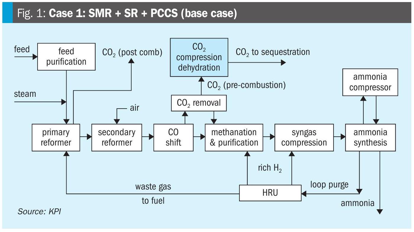
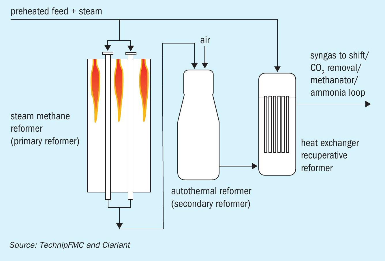
Over the past decade, alternative technologies to produce steam at attractive cost and with reduced (or even no) net CO2 emissions have been adopted rapidly and widely. In parallel, over the last two decades steam reforming technology licensors have shifted the efficiency and heat integration paradigm, and deployed advanced technologies capable of reutilising the heat contained in the hot process gas exiting the reformer as a heat source to drive the reforming reaction itself. Such technologies are commonly called “recuperative reforming” (Fig. 1) and mostly consist of either a heat-exchanger recupera tive tubular reactor that is placed in parallel to the primary and/or secondary reformers, or a heat-exchanger recuperative reformer placed in the convection section of a fired heater.
Recuperative reforming
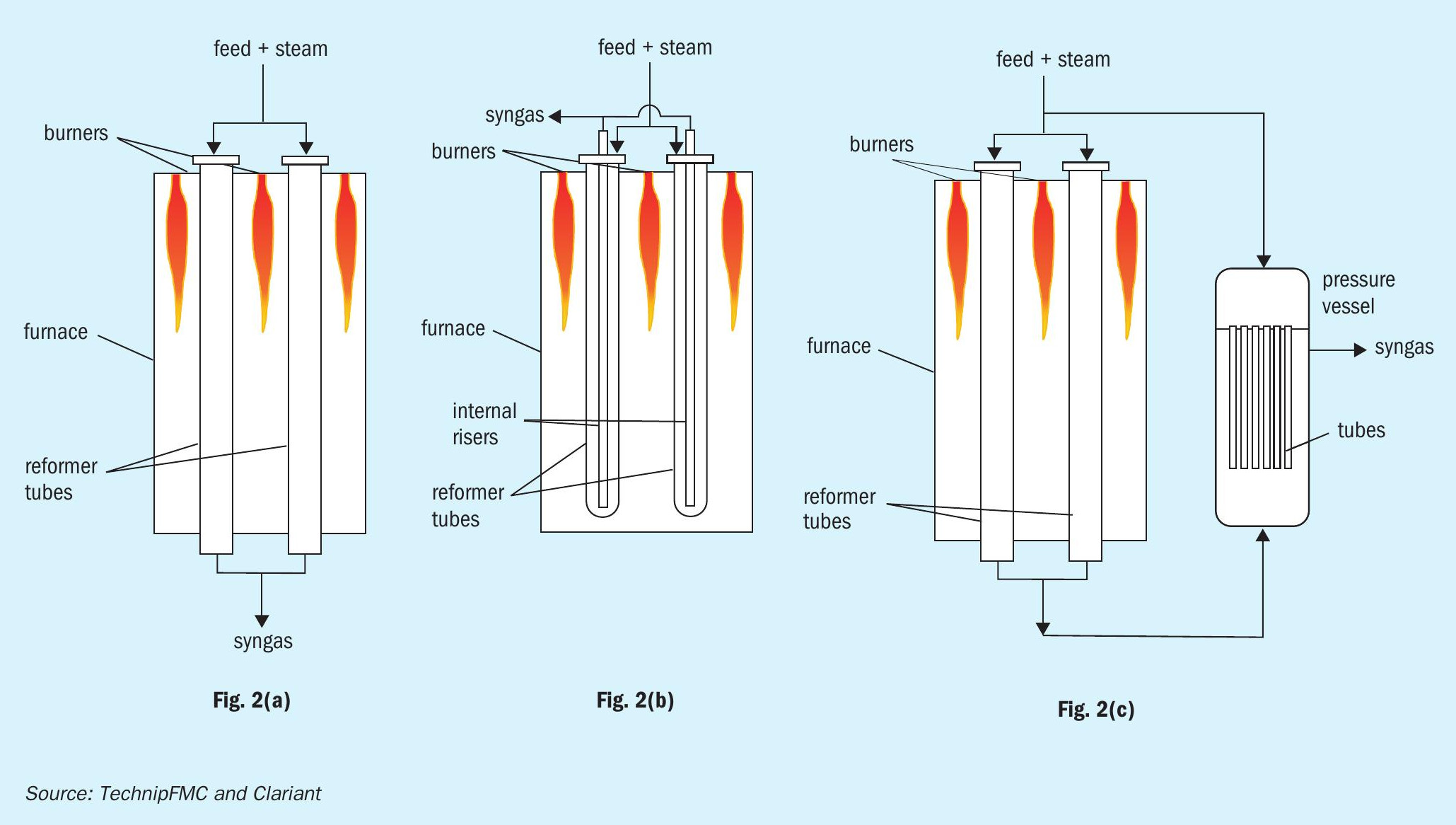
In Fig. 2(a), a conventional top-fired reformer is shown, with inlet and outlet situated at opposite ends of each reforming tube. The mixture of steam and feed is converted to syngas (CO+H2 ) by absorbing roughly half of the energy released in the reformer firebox through the catalyst tube walls. The syngas temperature at the outlet of the tubes is typically in the range of 750°C to 950°C, depending upon the desired conversion, hydrogen and CO yield.
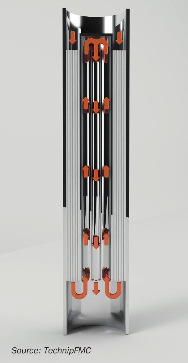
Fig. 2(b) depicts recuperative reforming technology, whereby a tube is inserted in a U-shaped reformer reactor, creating an annular counterflow arrangement to enable high grade heat recovery within the tube itself. In this layout the highest temperature is obtained at the end of the catalyst bed located at the U end of the tube, while the syngas exiting at the (top) outlet of the tube is partially cooled by counter-current heat transfer.
Fig. 2(c) shows an alternative design whereby the heat recuperation is carried out in a separate, external heat-exchanger recuperative tubular reactor, placed in parallel to the fired steam reformer. In this configuration, syngas exiting the fired reformer is routed to the parallel reactor as the heat source, while additional fresh feed + steam is converted on the tube side (cold side) of the reactor against the provision of this heat. This latter process integration option has gained interest in the context of syngas production capacity increase for ammonia and methanol plants as well as the recent wave of refinery revamps supporting the clean fuels market. For grassroots units, the heat exchanger recuperative reformer is also an attractive option since it improves the energetic performance of the plant and decreases the CO2 footprint per syngas unit production.
EARTH® technology
TechnipFMC and Clariant are introducing a new steam reforming product to the market to drastically improve both the energy efficiency and productivity of reformer tubes. TechnipFMC developed and patented a new recuperative tubular technology called EARTH® , for Enhanced Annular Reforming Tube for Hydrogen.
EARTH® is a drop-in insert comprising a concentric tubular assembly combined with a structured reforming catalyst in the outer annular space, which may be installed both in existing and new reformer tubes, to simultaneously achieve heat recuperation and higher throughput in steam reforming process (Fig. 3).
TechnipFMC and Clariant have joined their collective expertise in process, heat transfer and catalysis to develop and deliver EARTH® technology to the hydrogen and syngas market. The proprietary geometric layout in combination with the highly active, stable and mechanically robust catalyst coated on a tailor-made structured component promotes efficient and optimised heat transfer as well as low pressure drop. The development of the catalyst has been based on Clariant’s extensive multi-faceted know-how on structured catalysts for fuel cell applications and for mini hydrogen plants.
Technical and economic advantages
The EARTH® reactor technology has the advantage of being highly compatible with most existing commercial steam reformer units, which typically have inlet and outlet ends located at opposite sides of the furnace. Unlike first generation technologies using mostly U-shaped tubes with an internal riser, EARTH® enables easy, drop-in revamp of most existing reforming units. The geometry of the internal concentric tube assembly can be customised to meet the desired hydrogen output and steam production.
Stress and lifetime
Thanks to the internal heat recovery pass, the external heat flux demand is reduced, allowing for less intense firing and improved usage of the reformer tube material. Additionally, the outlet system, which is a critical mechanical item on modern steam reformer units, is exposed to much less severe conditions than the conventional technology, and is therefore subjected to less mechanical stress.
Efficiency and intensification
The significant improvements of EARTH include reducing firing, thus lowering the operating cost and/or enabling higher plant throughput, (i.e. the increased productivity and yield of the reformer tubes at equivalent firing). The technology is advantageous for achieving a capacity increase of up to +20%, at otherwise constant reforming conditions, with no or minor modifications on the steam reformer and heat recovery system. Moreover, EARTH® enables improved energy efficiency from the introduction of feedstock to the production of hydrogen or syngas, and carbon footprint values correspond to alternative recuperation technologies.
Catalyst performance
EARTH® technology uses a low pressure drop structured catalyst designed by TechnipFMC and Clariant to achieve highest activity and heat transfer combined with outstanding stability and mechanical robustness. The catalyst is suited to operate in the annular space between reformer tube and the outer concentric inner tube, coping advantageously with the mechanical stress attributable to thermal cycling and high temperatures, and the strongly reduced volume of the catalyst bed.
As a result, the gas throughput (gas hourly space velocity) in the catalyst tube can be increased significantly compared to conventional ceramic pellet technology while remaining within the desired pressure drop envelope. Concomitantly, the surface to volume ratio of the structure, as well as the geometrical design, allows for a step increase in activity and heat transfer properties compared to the random packed bed solution with traditional ceramic pellets. Overall the benefit of the intensified catalyst structure, in combination with the tailored internal heat recuperation facility, translates into an increase in syngas production of +20% per catalyst tube.
Carbon footprint
The EARTH® internal heat recovery enables the firing duty per unit syngas produced to be decreased, allowing for up to 10% CO2 emissions reduction per unit of value product, thereby achieving lower carbon footprint compared to conventional steam reforming technologies. In view of the lower reformer tube outlet temperature, due to the internal heat recovery, and the fact that the reformer outlet system normally constrains the severity of reforming, EARTH® paves the way to high conversion and low steam to carbon ratio that are key parameters to decrease the operating cost and to increase the overall energy performance of the steam reforming process.
Steam production
An implication of the EARTH® technology is a moderation of the steam production, very similar to other recuperative technologies. Although steam co-production has been used for decades as a practical and cost-effective method to recover high grade heat from the process and to valorise it by steam export to neighbouring consumers in the refinery or industrial complex, a trend observed in many integrated petrochemical platforms and refineries is to minimise steam export (even to zero steam export). In ammonia and methanol plants where steam is typically needed to drive compressors and other units (e.g. methanol distillation section), EARTH® is a promising technology to significantly reduce greenhouse gas emissions and to increase profitability by widening the operability envelope for consideration of alternative energy sources such as green electricity.
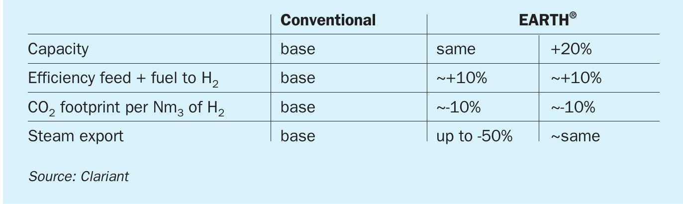
The implementation of EARTH® can be customised according to the targets and operation strategies of the hydrogen and syngas producers. An example of how EARTH® technology can deliver advantages according to operation objectives is shown in Table 1. These figures are indicative and case specific.
EARTH® technology has the advantage of being a drop-in technology that can fit in existing as well as new reformer tubes. It is therefore merely a catalyst changeout that is typically completed during a planned turnaround. Moreover, the implementation of EARTH® technology does not induce plot space issues. In case the EARTH® technology is supplied together with new tubes the end user may choose for catalyst preloading off-site.
The return on investment for the EARTH® technology depends obviously on site specific valorisation of utilities such as high pressure steam, the applicable CO2 emission regulations, the valorisation of the additional hydrogen generated compared to installation of new equipment. For all scenarios, TechnipFMC investigates closely with the end user the performance target and adapts the design of the EARTH® technology to achieve the best possible compromise.
EARTH® Implementation with Ak-kim
Akkim Kimya Sanayi ve Ticaret A.S. (Ak-Kim) is a subsidiary of Akkök Holding and is one of the fastest growing leading chemicals manufacturers in Turkey. Among other products, Ak-Kim produces hydrogen peroxide by mostly using the hydrogen product of the chlor-alkali process. To achieve cost effective hydrogen peroxide production, hydrogen from a small syngas plant is used to complement the primary hydrogen source. The CO product obtained from the syngas plant enters in an on-site solvent production plant. The small syngas reformer had been in operation for 20 years, at which point Ak-Kim decided to implement EARTH® to achieve fuel savings and to increase steam reformer efficiency in comparison to the conventional random packed ceramic catalyst tube technology.
The design of the EARTH® inserts was chosen to decrease steam export to a large extent and to maximise internal heat recovery, therefore reaching a maximum reduction of feedstock consumption. TechnipFMC took advantage of the end-of-life of existing tubes to propose a pre-packed delivery on site. The installation of the tubes was performed within one day, which is on a par with any tube replacement activity for such scale. Under the supervision of TechnipFMC and Clariant the plant was started-up very smoothly one week after the EARTH® tube installation, with an immediate observed step change performance of the steam reformer, in terms of both fuel consumption and steam export.
A performance test of the EARTH® tubes was completed successfully three weeks after the start-up, in early 2019. During this period the plant achieved stable operation at the nominal design plant capacity. The DCS recordings and the samples analysed by gas chromatography during the performance test have been used for reconciliation of the heat and mass balance of the complete plant, and for the EARTH® tubes themselves.
The conversion observed in the EARTH® tubes corresponded to an equilibrium temperature of 853°C and process gas temperature of 855°C, confirming that the catalyst performed very close to the equilibrium conversion, with the expected performance for the start of run. Furthermore, the measured pressure drop over the reformer tubes was less than 1 bar, well below the original pressure drop specifications corresponding to the conventional tubes loaded with ceramic pellets.
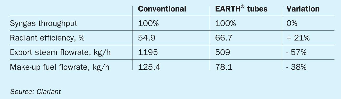
Table 2 summarises the most noticeable changes in the reformer, following EARTH® tube installation. The radiant efficiency expresses the ratio between the energy absorbed by the reaction of the process gas flowing through the radiant tubes and the energy released into the radiant box.
The energy recovered by the EARTH® tube is observed to be about 16% of the total heat absorbed by the process gas during the steam reforming process. This clearly demonstrates that EARTH® technology improves the energy efficiency of the reformer and leads to fuel savings compared to conventional catalyst technology. The radiant efficiency is significantly increased, by 21%. As a result, there is less duty available for steam generation resulting in a lower export steam flowrate (decreased by 57%). The fuel savings is about 38% (~400t/a of natural gas makeup), at equal production rate with equivalent separation performance, i.e. when PSA and membrane system show the same separation efficiency.
Remarkably, the CO2 emission of the plant (vent CO2 removal and flue gas) was reduced by about 20% (not considering CO2 equivalent of the CO product). Realisation of EARTH® ’s full potential may still be when the rest of the plant is debottlenecked (PSA and membrane, as well as the front end of the plant), at which time Ak-Kim is interested in additional production capacity.