Sulphur 392 Jan-Feb 2021
31 January 2021
Hidden opportunity: the water side of sulphur recovery units
SRU UTILITIES
Hidden opportunity: the water side of sulphur recovery units
Failure investigations, equipment design and process upgrade projects for SRUs often overlook the impact of water quality. In this article E. Nasato of Nasato Consulting and L. Huchler of MarTech Systems explore impacts of higher heat transfer rates, control of boiler and condenser water chemistry, conventional equipment design/configurations and monitoring program designs. SRU operators can improve the effectiveness of their failure investigations by implementing a broader, more holistic approach that assesses equipment design, process conditions, operating protocols and water quality issues.
During the last several decades, most of the focus to improve the efficiency and capacity of sulphur recovery units (SRUs) has been on the process side: raising the operating pressure to generate higher-value, higher-temperature steam and increasing the process-side temperatures to increase throughput. As refineries implemented process upgrades such as oxygen enrichment in existing assets, the higher heat flux sometimes caused unexpected failures in the waste heat boiler (WHB) and condensers during normal operation and shutdown. Recent technical publications have described water-related issues as root causes and/ or contributing factors to these failures, including inadequate distribution of boiler feed water, steam blanketing on the boiler tubes, and water-side fouling and corrosion. More importantly, this article describes solutions that address changes in design and operation of both the process side and the water side.
Background
In recent years there have been several published papers describing failures of SRU WHBs and identifying the key design and operating considerations to maximise the operability and reliability of the WHB. Many of the design and operating solutions are water-side issues: water chemistry, water circulation, heat flux on the water side, and impacts of commissioning, shutdown and layup on the reliability of the water side. It should be obvious that these water-side issues affect the downstream condensers. Because condensers produce low-pressure steam, water-side corrosion and fouling mechanisms progress more slowly. The message is clear: water-side failures in either the WHB or the condensers will create lost opportunity.
Overview of SRU water side
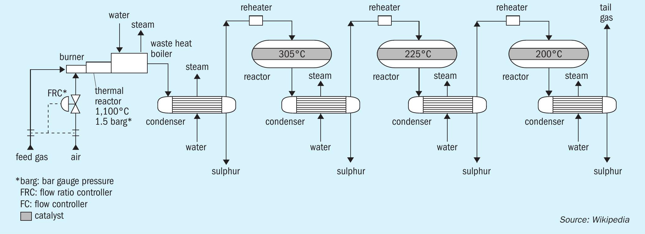
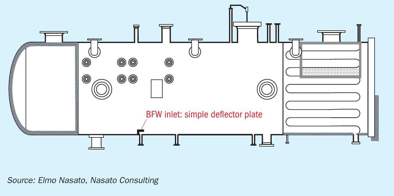
The WHB generates steam from the waste heat of the high-temperature combustion of hydrogen sulphide-laden gas in the thermal reactor. The condensers also generate steam in a shell-and-tube heat exchanger to indirectly cool the process, recover useful energy in the form of low-pressure steam and precipitate elemental sulphur (Fig. 1).
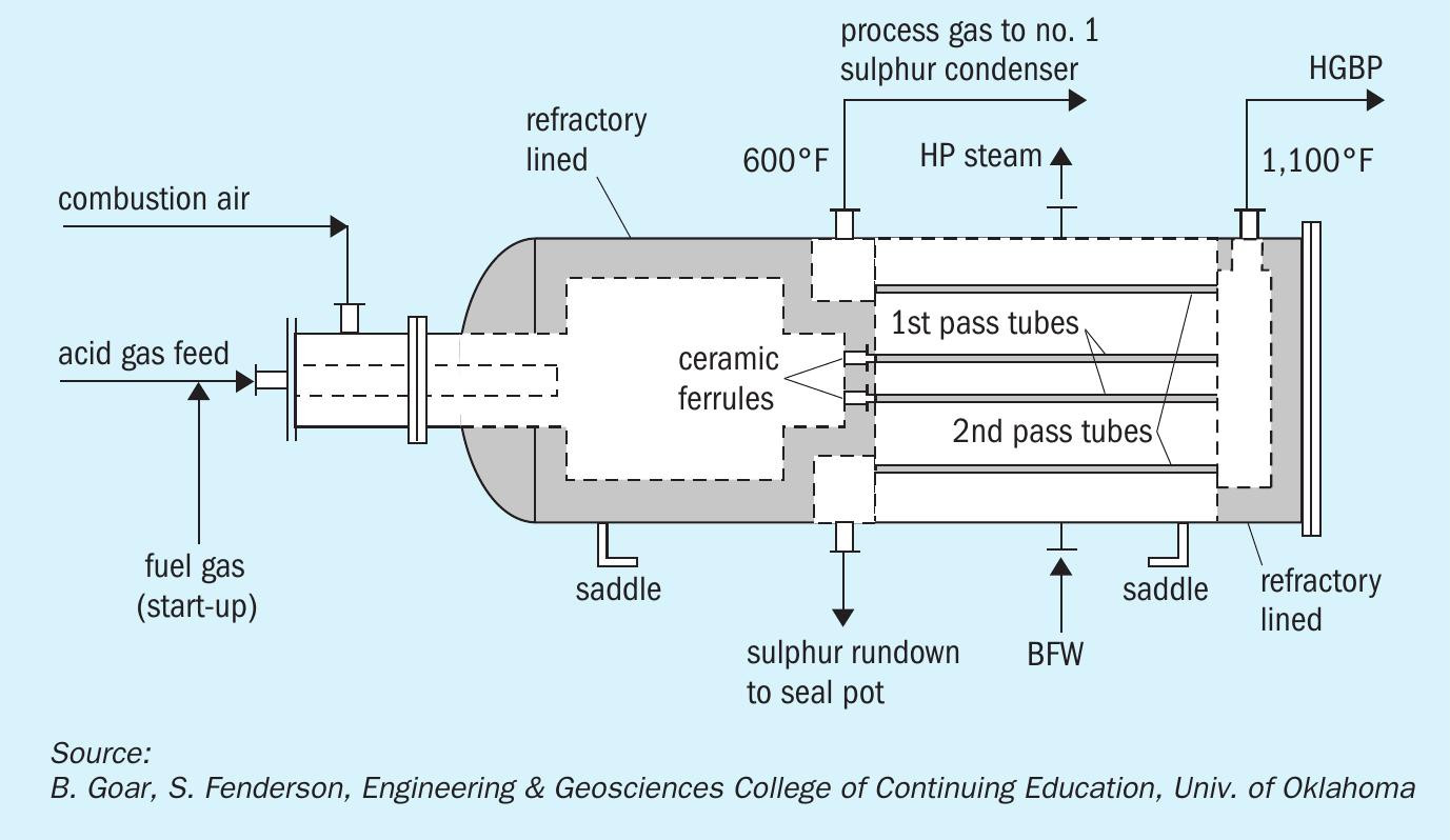
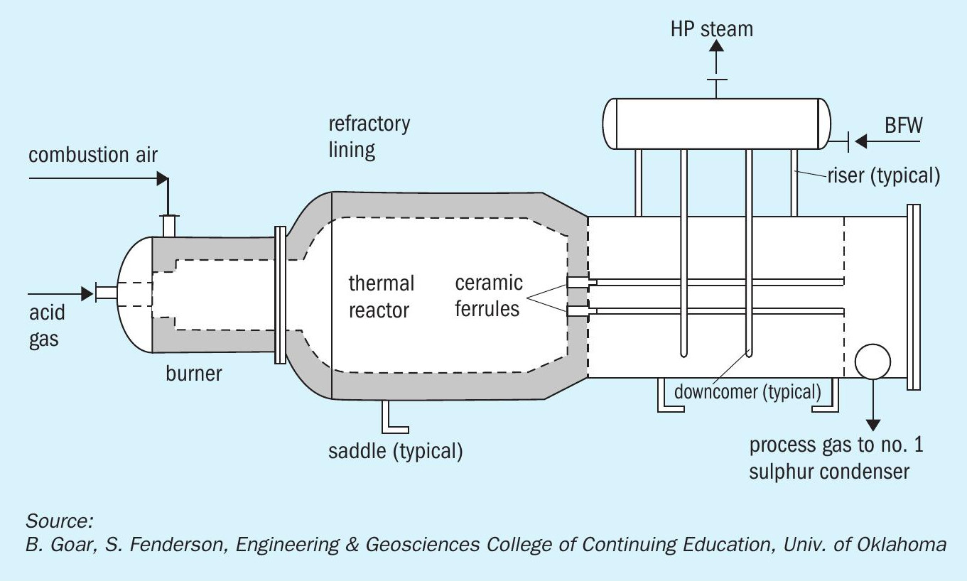
The nominal operating pressure of a modern kettle and thermosiphon WHBs (Figs 2 and 3) is typically in the range of 450 to 600 psig (31 to 41 barg), with the boiler water on the shell side.
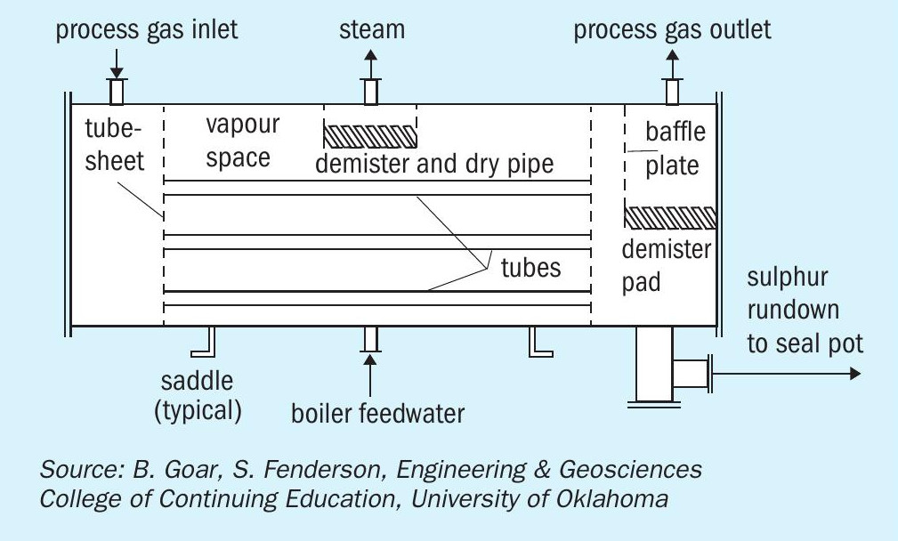
The nominal operating pressure of the condensers (Fig. 4) is in the range of 15 to 75 psig (1.0 to 5.2 barg), with the boiler water on the shell side.
The steam generators, WHB and condensers, share a common boiler feed water (BFW) supply. In the interest of simplicity, the addition of water treatment chemicals for corrosion and deposit control occurs upstream of all of these assets. The sulphur recovery process normally operates at a constant production rate. Consequently, these steam generating units also operate at steady-state. Operators routinely monitor the water chemistry of the BFW and the WHB boiler water (blowdown) and make adjustments to control the chemistry of this high-pressure steam generating unit. However, operators seldom monitor or make adjustments to control the chemistry of the condensers. Sometimes the water treatment supplier will sample and test the water chemistry of the condensers; however, usually the water side of these condensers receives no attention until they have a failure.
WHB mechanical design considerations
In the past, WHBs generated low pressure steam; modern designs generate much higher steam pressure, creating mechanical design and operating challenges. As a result, WHB failures are becoming increasingly more common. There are several design considerations that can increase the reliability of WHBs.
All WHB design considerations:
- WHB tube diameter;
- WHB tube pitch;
- WHB tube wall thickness;
- tube-sheet thickness;
- materials of construction;
- welding techniques for the tube-to-tubesheet welds;
- intermittent blowdown: number and location;
- continuous blowdown: location and collection lateral design;
- ferrule design and installation considerations.
Kettle design considerations:
- BFW location;
- BFW distributor design;
- steam outlet location;
- disengagement space design.
Thermosiphon design considerations:
- recirculation ratio;
- locations of risers and downcomers;
- steam drum design.
WHB operational issues
Safe operation of the WHB relies on effective cooling – transferring the heat from the hot gases in the tube side to the water in the shell side. Industry trends show that the water/steam-related shell-side failures are becoming the prevalent root cause of WHB failures. Experience with new WHBs confirms that equipment designers have not yet optimised the mechanical designs to prevent WHB failures. These water/steam-related failures provide harsh reminders of the importance of keen attention to address design issues in WHBs to ensure safe, reliable operation.
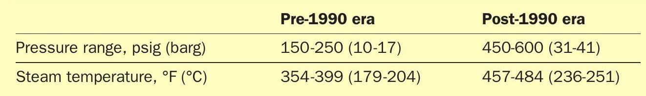
From a shell-side and water treatment perspective, the key items that have changed in the industry over time include: SRU operating pressures and temperatures (Table 1) and WHB operating pressure and oxygen-enrichment processes that increase heat flux. For kettle-style WHBs, the more stringent, high heat flux operating modes have resulted in failures attributed to poor water distribution and/or vapour disengagement issues.
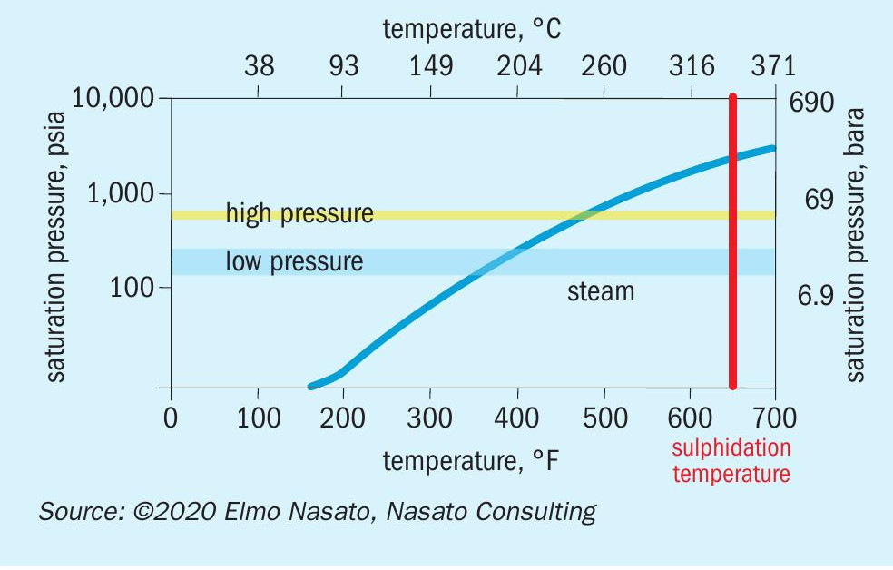
The typical material of construction of a WHB is carbon steel. For these modern SRUs that have higher-pressure/hightemperature steam generation, there is a smaller margin of error to prevent the operating temperature of the water-side heat transfer surface of the WHB from reaching the sulphidation temperature. Improper water treatment that creates insulating deposits on the water-side heat transfer surfaces or equipment configurations that prevent adequate water flow create a risk of the shell-side exceeding the sulphidation temperature and causing catastrophic damage. This reduced margin increases the risks for SRUs that use natural gas during start-up and shutdown, especially in oxygen-enriched processes that have elevated operating temperatures. The higher operating temperature of the WHB steam-side has also presented new challenges to the WHB design and operation (Fig. 5).
Excessively high temperature affects the reliability of the WHB by degrading the tube sheet system that includes the refractory, ferrules, tubesheet, tube-to-tubesheet joint, and tubes. Thermal cycling as well as rapid changes in process and refractory temperatures are detrimental to the reliability of the WHB tubesheet system. Thermal cycling events might be a result of scheduled shutdowns; however, a more likely cause is sudden, unplanned shutdowns. Shutdowns cause thermal and mechanical stresses to the WHB equipment that may result in localised steam blanketing at the hot end of the tubesheet. In well-designed systems, the thermal reactor and WHB has a thermal cycle life expectancy as high as 20 years; inadequate designs may have as low as two or three years of thermal cycle life expectancy. Obviously, damage to the tube sheet protection system causes a loss of system reliability.
Kettle vs thermosiphon WHB design
Field experience has shown that thermosiphon boilers are generally less vulnerable to failure than kettle-type steam generators. For high temperature applications, properly designed thermosiphon boilers provide the benefit of very high recirculation rates that creates a smaller temperature gradient across the tubesheet, reducing the risk of localised areas of high heat flux and non-nucleate boiling. The design of kettle reboilers must have a sufficiently large disengaging space to minimise the back pressure from the steam header and reduce the risk of steam blanketing on the tubes.
Preventing steam blanketing is the biggest challenge in the design and operation of WHBs. The tube pitch arrangement is critical, especially for thermal stage operating at high temperature processes such as oxygen-enrichment. A square pitch rotated at 45° creates less back pressure on the steam side of the tube bundle, resulting in more efficient vapour disengagement and a lower risk of steam blanketing. High temperature thermal stage operation (e.g. straight through ammonia destruction or oxygen-enriched operation) can reach temperatures above 2,300°F (1,260°C), creating a dangerously high LMTD (log-mean temperature difference) in the WHB. This high steam-side flux result in approximately 50% of the steam generated in the first 25% of the boiler tube length. Clearly, it is important to calculate the profile of steam flux rates over the length of the WHB tubes to reduce the risk of damage from steam blanketing.
Heat flux is determined by the radiant contribution on the process gas side and the heat transfer coefficients on the process-gas side and the water side. Engineers can establish appropriate temperature and mass flux operating conditions to provide reliable service for a specific WHB design and study the limitations of heat flux in the turbulent region at the end of the ferrule to assess the ability of the tubesheet protection system to maintain “safe” metal temperatures. Frequently designers erroneously base the WHB design and evaluation exclusively on convective heat transfer; this approach ignores the contribution of radiant heat transfer. The radiation component can contribute up to 20% additional heat flux, creating a significant impact on the calculation of the surface area for the WHB and the piping design for the BFW and steam generation systems.
As the operating pressures of SRUs have increased, both thermosiphon and kettle-type WHBs have higher heat transfer coefficients. Higher heat transfer rates increase the need for proper mechanical design of feedwater inlet and distribution, steam separation/discharge, continuous blowdown collection and intermittent blowdown systems. As described in the next section, it is imperative that the WHB process design ensures an adequate volume and flow of boiler feed water at the critical inlet tubesheet location. From an operational perspective, properly implemented intermittent blowdown may protect the tubes, especially in the location of highest steam flux near the inlet tubesheet.
Process upgrade – oxygen enrichment
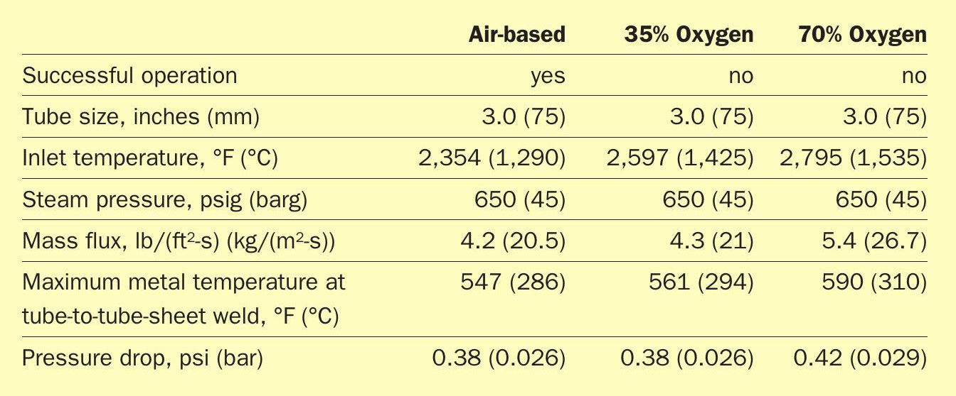
Oxygen enrichment increases the sulphur production rate of an existing SRU. The WHB hydraulic profiles of the air-based and oxygen-enriched process are virtually identical; the tube mass flux and tube-side pressure drop values are identical for both modes of operation. The only difference is a requirement for flame moderation for high-level oxygen-enriched operation (Table 2).
Increasing the sulphur production rate increases the heat flux and the steam production rate in both the WHB and the condensers. More importantly, higher heat flux creates a risk of non-nucleate boiling in localised areas of inadequate water circulation – a dangerous phenomenon also known as steam blanketing.
An evaluation of the impact of oxygen enrichment on the WHB must include an analysis of the heat flux rates along the entire length of the tubes, especially at the highly turbulent area on the upstream side of the ferrule. The heat flux should not exceed 50% of maximum nucleate flux at design conditions, and 65% for maximum service conditions. These limits ensure that the temperature of the tube wall is within 18°F (10°C) of the saturation temperature at design, well below the 72°F (40°C) break-over to Leidenfrost film boiling (exceedance of the critical maximum nucleate flux).
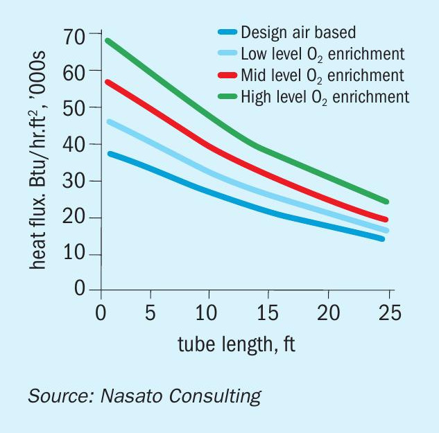
The tube-to-tube pitch diameter is critical to ensure proper evacuation of the produced steam. The practical recommendation for the design of steam generators is an overall heat flux of 20,000 Btu/(hr·ft²) (65,091 W/m²) for kettle-type boilers and 30,000 Btu/(hr·ft²) (94,637 W/m²) for thermosiphon boilers. The heat fluxes for the oxygen-enriched operations are much higher at the hot end of the tubesheet in the WHB (Fig. 6). The high steam generation rates in combination with the tight ligament causes overheating of the tube-totubesheet weld and creates a risk of failure.
Water-side control issues
Proper design and location of the BFW inlet and the continuous and intermittent blowdown connections can reduce the risk of localised areas of inadequate water circulation, off-spec water chemistry and steam blanketing in both the WHB and the condensers. Confirming the process capability for blowdown based on the feedwater quality and ensuring consistent and accurate level control can reduce the risk of corrosion and fouling of heat transfer surfaces and steam blanketing, tube-thinning, carry-over and compromised continuous blowdown flow.
BFW Inlet
The location and configuration of the BFW inlet can have a dramatic effect on the circulation in both the boiler and the condensers. The most rudimentary BFW inlet consists of a transfer pipe that ends a few inches beyond the penetration of the wall of the pressure vessel, with perhaps a 90° turn to direct water along the longitudinal axis (Fig. 7).
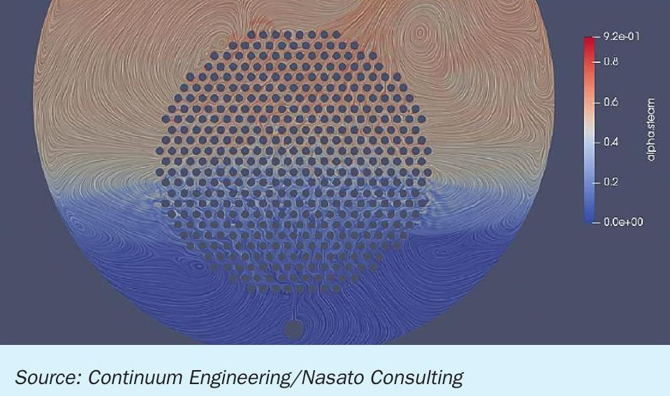
A robust design for the BFW inlet is similar to the inlet lateral for a conventional water-tube fired boiler: a small-diameter pipe that extends the length of the steam drum at 12 o’clock (bottom of steam drum) with holes equally spaced along the entire length at the 12 o’clock position. CFD models map the thermal gradient for a WHB BFW inlet distributor properly installed (Fig. 8a) and improperly installed: rotated ~45 degrees (Fig. 8b). The thermal gradient in Fig. 8b compromises the steam generation process, creating a risk of localised low flow areas and poor evacuation of the steam/water mixture from a portion of the tube bundle.
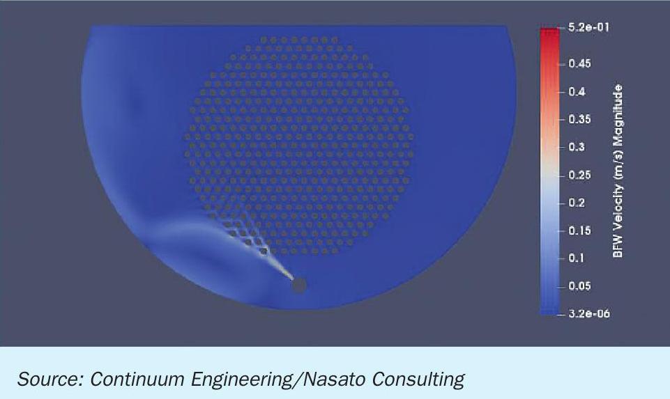
A poorly-designed or improperly-installed BFW lateral compromises proper circulation, creating a risk of inadequate water circulation and off-spec water chemistry in both the WHB and the condensers.
Continuous blowdown
For a kettle-style steam generating WHB or condenser, the location of the continuous blowdown collection lateral is just below the water’s surface where the concentration of dissolved solids is the highest. Continuous blowdown removes a portion of the concentrated boiler water and any low-density suspended solids floating on the water/steam interface. A robust design for the continuous blowdown collection lateral is similar to the inlet lateral for a conventional water tube fired boiler: a small-diameter pipe that extends the longitudinal length of the steam drum at an elevation just below the waterline with holes equally spaced along the entire length at the pipe (3 o’clock or 9 o’clock) position. Fig. 9 shows a continuous blowdown collection lateral on the left-hand side of the photograph.
Intermittent blowdown
With softened water make-up, the purpose of routine, manual intermittent blowdown is to reduce the risk of deposits on heat transfer surfaces by removing the precipitated calcium-phosphate sludge formed in on the heat transfer surfaces. Most plants no longer conduct routine intermittent blowdown because the modern dispersants have eliminated precipitated sludge. For condensers that use high-purity water (reverse osmosis permeate, demineralised water, condensate), routine intermittent blowdown is not necessary; it wastes energy, water, and boiler water chemicals.
Sometimes designers mistakenly eliminate the intermittent blowdown connection in new SRU equipment. Non-routine intermittent blowdown is necessary to address process contamination of the boiler water or upsets in feedwater or boiler water chemistry. The need for intermittent blowdown may not always be obvious: leading indicators include extended periods of non-conforming water treatment, poor quality condensate, and unscheduled shutdown events.
Because modern boiler water treatment does not require routine intermittent blowdown, most operators lack the training necessary to properly operate the manual intermittent blowdown valve. Operators must quickly open the valve to 100% for several seconds to allow the high velocity stream to move accumulated sludge and/ or corrosion products followed by rapidly closing the valve to prevent discharging too much boiler water. In this era of Safety Instrumented Systems (SIS), the risk of not closing the valve quickly enough is huge: a low water level alarm will trigger a unit shutdown and route the combustible gases to the flare, a reportable event that may have environmental regulatory and legal consequences. Training operators to operate the intermittent blowdown control valve properly and safely will increase the reliability of the SRU and reduce the risk of an operator error.
Finally, the design of an intermittent blowdown system should ALWAYS have two valves in series: the specially designed “impulse flow” intermittent blowdown valve and a classic isolation valve. There is always a risk that a single valve will “fail open,” tripping the unit and creating a major incident.
Blowdown valve sizing
Historically, the feedwater quality for sulphur recovery units is a mixture of sodium zeolite softened make-up water and condensate. When refineries began to install reverse osmosis (RO) units to create make-up water for fired and waste heat boilers, WHBs and condensers began to experience high rates of corrosion. Investigation revealed poor control of water chemistry due to high blowdown flowrates. The original blowdown valves for the larger flowrate of softened water make-up were oversized and not suitable for modulating the smaller flowrates for RO make-up. The mismatch between the valve size for softened water versus RO permeate is large; prior to installing smaller blowdown valves, operators were conducting blowdown by modulating the flow through the boiler water sample line. Astonishingly, equipment designers have continued to consistently size the blowdown valves in both WHB and condensers as if the makeup were softened water.
High purity make-up
Control of boiler chemistry is more critical and more difficult in steam generators that have high-purity feedwater (e.g. 100% condensate) than systems that use softened water as part or all of the feedwater. The lack of buffering in high-purity water requires more intensive monitoring and more precise control of water chemistry to “safe” specification limits to ensure reliable operation. WHBs and condensers using high purity make-up will have a high risk of flowassisted-corrosion (FAC) when all of the following operating conditions are present:
- reducing conditions;
- high-purity water;
- highly turbulent boiler-water flow conditions in condensers.
The classic candidate for FAC is an SRU system that has high purity make-up water, uses an organic oxygen scavenger and has modified the sulphur recovery process to increase throughput. Fig. 10 shows FAC on at the 6 o’clock position (bottom) of the lowest row of tubes at the inlet tubesheet in the condenser.
Reducing one or more of these three operating conditions below the “critical” level will reduce and, at sufficiently low levels, eliminate FAC. Operators of SRUs with high purity make-up should note that conformance ASME guidelines are not sufficient to ensure reliable operation. The ASME guidelines do not specify limits for hydroxide (“OH”) alkalinity; typically the chemical supplier specifies the minimum specification limits for boiler water alkalinity based on the boiler feed water quality, duty cycle and historical system reliability.
Some refineries that have high-purity feedwater have implemented coordinated pH/phosphate (PO4 ) programs for their boiler and condenser water. A coordinated pH/PO4 treatment program creates a buffering system for phosphate and caustic to avoid the risk in high purity boiler water of under-deposit corrosion damage from caustic concentrating under iron deposits (caustic gouging) on heat transfer surfaces. The risk of caustic gouging is very low for steam generating systems operating at or below 600 psig (31-41 barg) pressure; the risk increases dramatically for higher-pressure steam generators.
The key consideration is the return on investment for implementing coordinated pH/PO4 treatment programs in the SRU. A separate chemical feed and control system is required for the WHB, moderate-pressure condensers and low-pressure condensers because the chemical feed rate depends on the operating pressure of the steam generator. Controlling the coordinated pH/ PO4 treatment program is no small task; as the feedwater quality changes in pH (sodium concentration), operators must adjust both the chemical treatment feed rate as well as the blowdown. Finally, a coordinated pH/ PO4 treatment program is not very forgiving; failure to strictly conform to the specification limits creates a risk of caustic gouging. The bottom line: the complexity to control a coordinated pH/PO4 treatment program in an SRU is not worth the benefit.
Refineries have proven that an SRU can operate reliably on either softened water make-up or high-purity boiler feed-water (BFW) provided that the chemical supplier recommends the correct chemical treatment program, the chemical feed and blowdown systems have sufficient process capability and the operators diligently monitor and make timely adjustments for chemical feed and blowdown rates.
Poor level control
The proper water level in the condenser is above the top row of tubes, an operating condition that maximises heat transfer and system reliability. Continuous, proper level control is critical for both WHB and condensers. With the adoption of safety instrumented systems (SIS) for these kinds of critical processes, plants have installed redundant measurement and control systems. Aging equipment, failure to conduct preventative maintenance and calibration, and operator error can be sources of poor level control.
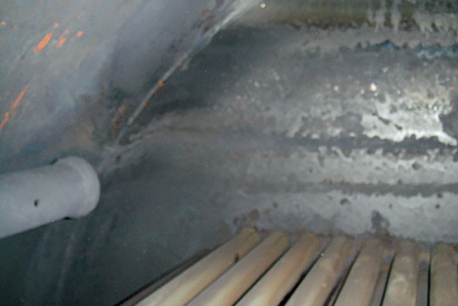
Another source of poor level control is the design of some condensers: insufficient disengagement space above the water level to prevent carryover into the receiving steam header. Operators can quickly recognise signs of carryover: decreasing steam temperature (and pressure) in the outlet steam header and, in severe cases, water leaking from flanges on the connection to the steam header. Typically, operators will take steps to minimise carryover by adjusting the setpoint on the level controller. Figs 11 and 12 confirm that when a plant does not have strict limits on the level controller, operators may inadvertently decrease the water level below the top tube row, creating a risk of steam-side burning and tube-thinning that leads to premature failure and unplanned outages.
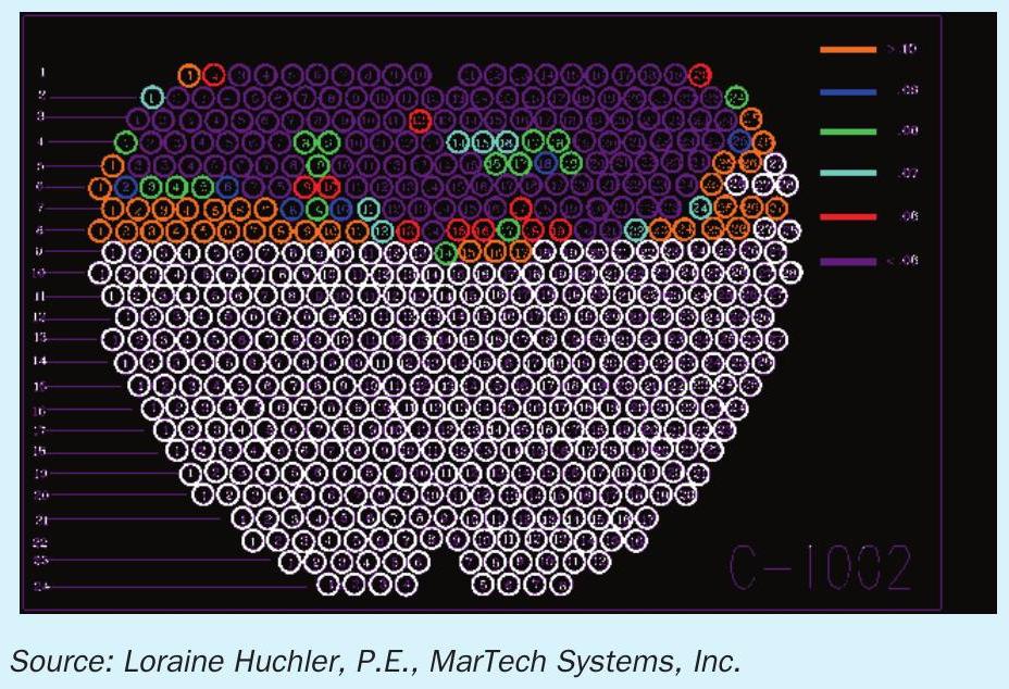
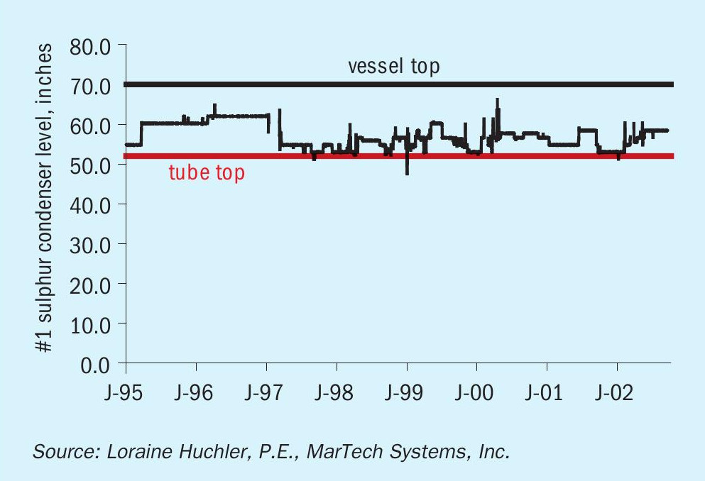
It is difficult to document the exact water level; however, the data in Fig. 11 implies that some of the tubes in the top rows were exposed to steam some of the time and tubes at the steam-water interface were alternately exposed to boiler water and steam. In this plant, poor water treatment resulted in severe, irreversible fouling in the WHB and a loss of approximately 10% heat transfer efficiency, forcing the first condenser to operate at an average inlet process side temperature of 860°F during the period immediately prior to the failure (maximum OEM specification of 775°F). Not surprisingly, Fig. 12 shows widespread tube-thinning damage in this first condenser.
Some sulphur condensers have a steam separator (knock-out drum) located at the outlet to eliminate entrainment of boiler water in steam. This same refinery installed external steam separators on every condenser to prevent future premature failure of condenser tubes.
Water-side operating issues
The focus to improve the efficiency and capacity of the process side of the SRU for the last several decades has resulted in several clear trends: longer service runs, shorter turnaround periods, increased shutdown and commissioning activities for equipment retrofits for process upgrades. And the trend of increasing water-side failures in the WHBs is a direct result of these process upgrades and the absence of robust, effective failure investigations.
Longer service runs
Refineries have been increasing the interval between turnarounds as suppliers improve the reliability of process-side components. Consequently, poor conformance and monitoring of water chemistry to ASME guidelines and/or poor compliance to the water treatment program specifications often becomes the limiting factor for the turnaround interval. For example, iron deposits on heat transfer surfaces in the WHB due to inadequate chemical treatment/poor blowdown control can cause a short or long term WHB tube failure. Minimising the risk that water-side issues will limit the interval between turnarounds requires an effective operating discipline for monitoring and control of the water chemistry within the specification limits and a commitment to maintain equipment such as blowdown control valves, boiler feedwater inlet distributors, continuous blowdown collection laterals, level controllers and steam separation equipment.
Shorter turnarounds
Water-related issues such as inspections and equipment modifications are often the lowest priority during turnarounds. All turnarounds have aggressive schedules and repairs that take longer than expected. Consequently, it’s highly likely that the plant will not complete some water-related issues. Unfortunately, water-side problems not addressed during turnaround may become the limiting factor for reliable operation in the future. Analysing operating data and historical inspection reports to assess the impact of existing water-related issues on process-side efficiency may increase the priority of solving waterside problems during turnaround.
Failure investigations
After a failure, economics drive the pressure to return a unit to service. As an example, refinery staff will typically plug individual tubes in a WHB or condenser, because pulling the tube bundle and cutting a single tube sample, unless the tube happens to be in an outer location, is not feasible. Without metallurgical analyses, the only evidence might be photographs of the heat transfer surfaces from visual inspections that often fail to show the contour of the corrosion of the surface or corrosion within the tube bundle.
A more fundamental challenge to identifying water-related failure mechanisms is a lack of familiarity about the purpose and proper configuration of the internal components in the WHB and condensers. One plant had disconnected the inlet boiler feedwater lateral in all of the condensers to allow them to lower the water level to reduce the frequency and degree of carry over.
The most ironic part of failure investigations is the unconscious bias towards process-related root causes. Typically, plant staff do not even consider water as a root cause or contributing factor. In one case, a refinery client had several SRU experts examine the photographs, model the process and test numerous hypotheses over the course of a year before asking the water treatment expert to review the data and properly identify the root cause – and the corrective action.
Commissioning
The greatest water-related risk during commissioning of an SRU is the hydrotest. Although there may be a procedure and a specification for water quality, the demands of the schedule and the inevitable delays typically result in a failure to promptly drain – or ever drain the hydrotest water. The resulting corrosion seldom causes a failure or permanent damage; however, the large quantities of iron corrosion products during start-up compromises the water quality and can create deposits on heat transfer surfaces that create risk of overheat or under-deposit corrosion and subsequent premature failure. There is another risk of an “off-spec” hydrotest: in the event of an equipment failure after hydrotest or shortly after commissioning, it will be difficult, if not impossible, to definitively identify the initiation of the root cause of the damage.
Shutdown/lay-up
Refineries seldom lay-up an SRU unless the refinery is completing repairs or installing equipment for a process upgrade. Shutdown occurs prior to every turnaround, at every failure and for emergencies such as a severe hurricane.
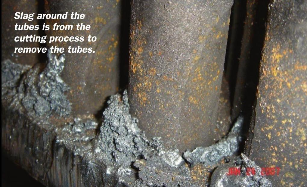
During controlled shutdowns, plant personnel must purge the residual sulphur gases. The classic “burn-out” procedure requires operation of the reheaters located at the outlet of the condensers and continuous circulation of the boiler water to cool the condenser tubes and prevent shortterm overheating of the condenser tubes. Reviews of historical bulk gas temperatures at the reheater effluent show high temperature spikes during this “burn-out” procedure. Fig. 13 shows two temperature excursions for this “burn-out” procedure. These temperature excursions during shutdown were severe enough to cause corrosion in all of the condensers, including the last condenser. Fig. 14 shows the top row of tubes at the hot tubesheet with corrosion at the 6 o’clock position.
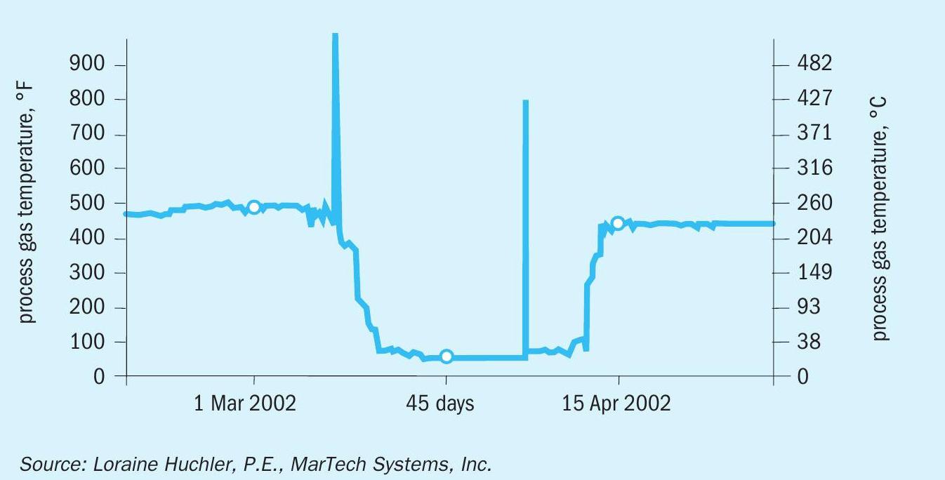
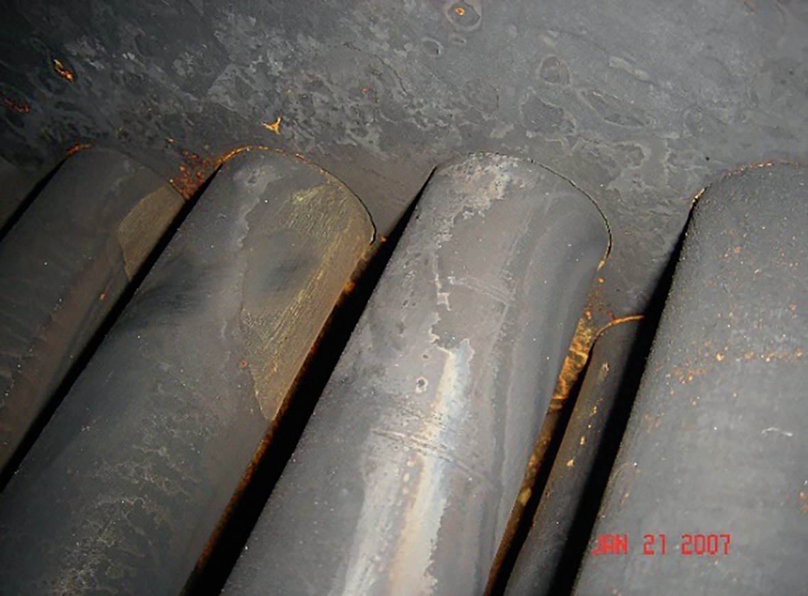
This plant upgraded to oxygen-enrichment that increased the process temperatures. The additional heat causes a rapid increase in steaming rate, especially at areas of high metal mass such as the inlet tubesheet. A steam blanketing effect traps steam between the tubesheet and the tubes, insulating the water side of the tube surface from the cooling effects of the condenser water and causing localised “steam-side burning” or rapid oxidation of the steel tube surfaces. The patterns of the affected tubes are consistent with a trapped pocket of steam, causing more severe corrosion at the bottom of the highest affected row of tubes and on the sides of adjacent tubes in the bundles. This short-term temperature excursion occurred only in condensers that have upstream reheaters.
This plant implemented a low-emissions shutdown procedure that replaces the catalyst bed burn-out process with a hot/cool nitrogen gas sweep, significantly reducing the temperature excursions that occurred during the conventional shutdown process.
Following shutdown, it is a best practice to immediately drain and lay-up the WHB and condensers to prevent corrosion. Fig. 15 shows localised corrosion on the hot tubesheet following a shutdown: small, grey-coloured depressions and small rust-coloured spots.
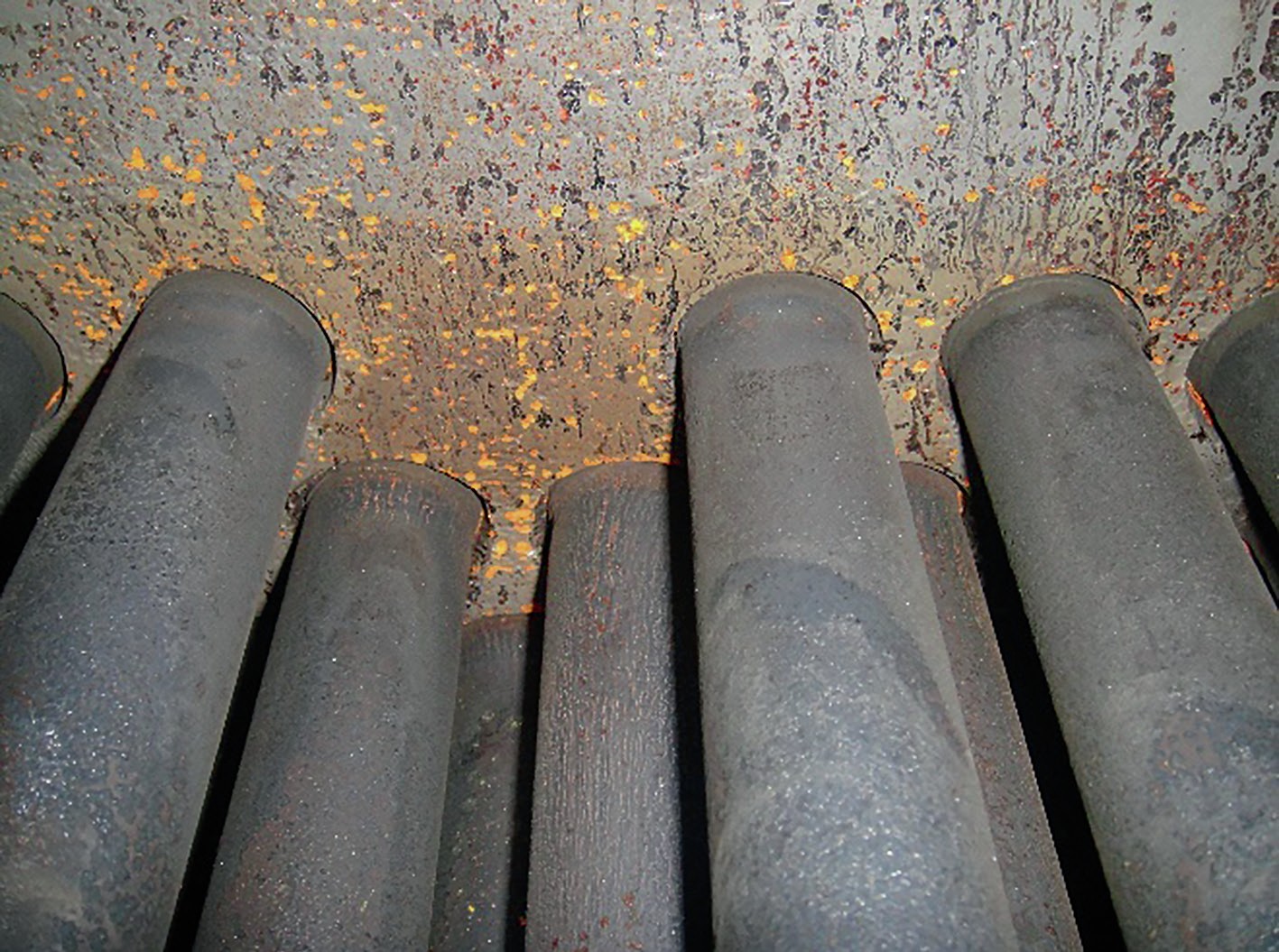
The grey-coloured depressions are consistent with past corrosion from oxygen dissolved in water. The rust-coloured spots appear to be tubercules – active corrosion sites that form in oxygen-saturated water such as during hydro testing of new condensers, or stagnant water during start-up or shut-down procedures.
Conceptually, dissolved oxygen corrosion starts as soon as oxygen adsorbs into the stagnant water; corrosion starts at the air/water interface. From a practical perspective, plant personnel should take steps to protect against the risk of dissolved oxygen corrosion if the system will have stagnant water for more than 24 hours. Options to manage the risk of corrosion include nitrogen blanketing or the addition of a volatile amine-based corrosion inhibitor.
Conclusion
Process upgrades, OEM design and operating protocols on the process side are inextricably linked to issues on the water side such as water chemistry, water treatment, blowdown valves, BFW inlet laterals. The objective is to build awareness for equipment designers, process design professionals, engineering firms, process engineers, operations staff, water treatment service representatives and consultants to embrace a broader, more holistic approach to evaluate root causes and identify contributing factors, to design equipment and processes, to operate plants, to monitor and control water treatment programs and to conduct failure investigations.
References