Nitrogen+Syngas 369 Jan-Feb 2021
31 January 2021
NOx reduction from steam methane reformers
NOX EMISSIONS
NOx reduction from steam methane reformers
NOx emissions from chemical processes such as steam methane reforming contribute to air pollution. The chemical industry is required to take steps to lower such emissions. Technology, developed for related industries, can be designed and optimised to reduce NOx emissions from steam methane reformers. Emission control experts can use a combination of modelling and experience to guide plant operators in recommending and designing optimum, sometimes tailor-made solutions. In this article different options are discussed including low NOx burners, selective catalytic reduction, selective non-catalytic reduction and high emissivity ceramic coatings.
Oil refineries, petrochemical and chemical facilities are widely considered as some of the main sources of air contaminants, including sulphur oxides (SOx), nitrogen oxides (NOx), and carbon dioxide (CO2 ). These pollutants pose an environmental hazard.
Multiple independent and not-for-profit organisations, including the Oil and Gas Climate Initiative and the Organisation for Economic Cooperation and Development (OECD), provide advice on emissions reduction. A report by OECD states that several countries attained the emission ceilings of the Gothenburg Protocol for 2010, but other countries had difficulties in doing so. Further efforts will be required to meet the new objectives for reducing emissions by 2020 and beyond.
ESG initiatives around emissions reduction
Reducing emissions while ensuring adequate supply of hydrocarbon derivatives is a complex issue for refinery operators and chemical producers. At a company level, Environmental, Social, and Corporate Governance (ESG) initiatives have been put in place to provide practical solutions to these emissions issues, while continuing daily operations. Many industries and economies rely on hydrocarbon derived products. Our everyday products, including medicine, clothing, toothpaste and even solar panels start their lifecycle as unrefined petroleum. Demand for most of these items is not expected to drop with our growing population, while initiatives focusing on production from plant-based materials are still in their infancy.
The problem with NOx
Nitrogen oxides (NOx), is the generic term for a group of highly reactive gases, all of which contain nitrogen and oxygen in varying amounts. Many are colourless and odourless but one common pollutant, nitrogen dioxide (NO2 ) is identifiable as a yellowish-brown layer over many urban areas.
Nitrogen oxides form when fuel is combusted or oxidised at high temperatures, such as an internal combustion engine or in industrial processes such as steam methane reforming. The primary sources of NOx are motor vehicles, boilers, furnaces, and other industrial, commercial, and residential sources that combust hydrocarbon fuels.
NOx and sulphur dioxide react with other substances in the air to form acids which fall to earth as rain, fog, snow or dry particles. Acid rain causes deterioration of car finishes, buildings and historical monuments, and causes lakes and streams to become acidic and unsuitable for many species of fish.
NOx reactions can also cause the formation of small particles that penetrate deep into the lungs and can cause or exacerbate respiratory disease such as emphysema and bronchitis, and aggravate existing heart disease.
Nitrate particles and nitrogen dioxide can block the transmission of light, reducing visibility. Ozone (O3 ) is a gas that occurs in the Earth’s upper atmosphere and at ground-level. In the upper atmosphere ozone acts as a protective layer against ultra-violet (UV) radiation. Ground-level ozone, is created by a photo-chemical reaction between nitrogen dioxide and volatile organic compounds (VOCs). Formation of ground-level ozone is dependent on weather and concentrations are typically the highest on hot summer days, with little or no cloud cover and very little wind. Motor vehicle exhausts and industrial emissions are two of the major sources of NOx and VOC emissions that help to form ground-level ozone. Rural areas can also experience increased ozone levels when wind carries ozone hundreds of miles from its original source.
Even at low levels, ground-level ozone triggers a variety of health problems including asthma attacks, reduced lung capacity, and increased susceptibility to respiratory illnesses like pneumonia and bronchitis. Ozone can cause permanent lung damage after long-term exposure and can irritate lung airways and cause inflammation. People with respiratory problems are most vulnerable to elevated ozone levels. Ground-level ozone also damages the leaves of trees and other plants, ruining the appearance of cities, national parks, and recreation areas. Ozone reduces crop and forest yields, and increases plant vulnerability to disease, pests, and harsh weather.
Sources of NOx emissions
NOx emissions are derived from three sources: fuel NOx, thermal NOx and prompt NOx. The predominant sources of NOx emissions from petroleum refineries and petrochemical plants are combustion sources and the predominant NOx emissions, in terms of concentration, are nitric oxide (NO) and nitrogen dioxide.
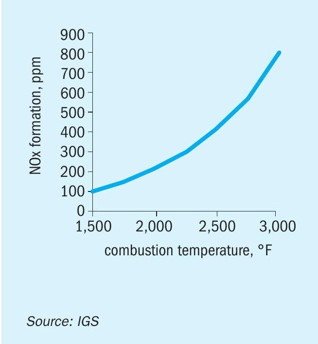
In high temperature, gas-fired process heaters, including refinery fired heaters, steam methane reformers and steam crackers, the NOx emissions originate mostly from thermal NOx. These are formed when nitrogen and oxygen in the combustion air combine at the high temperatures in a flame and combustion products (see Fig. 1).
Fired heaters are increasingly looked at by ESG committees as both sources of high NOx emissions and potential candidates for a good percentage of NOx reduction, contributing to the total emissions reduction across the facility. Steam methane reformers (SMRs), in particular, are inherently higher NOx producers than conventional fired heaters because of their higher firebox temperatures.
NOx reduction methods and technologies
As per normal practice, NOx reduction methods and technologies are based on the following fundamental assumptions:
- Nitric oxide (NO) is the predominant form of NOx that is formed in the combustion zone and emitted from the combustion device.
- The formation of nitric oxide is very dependent on the concentration of available oxygen and on the reaction temperature.
- Fuel-bound nitrogen is a major contributor of NOx.
Based on these assumptions, NOx reduction control technologies are focused on:
- preventing the formation of NOx during the combustion process, either by reducing the nitrogen content in the fuel, by limiting the access of the reaction to oxygen or by reducing the reaction temperature;
- destroying the NOx after combustion but before the combustion products leave the facility.
The following four cases provide examples of Casale case studies where reducing NOx emissions was one of the main requirements.
Case 1
Casale was awarded an EP base project for an ammonia plant revamp to reduce energy consumption and increase plant production capacity as well as reducing the NOx emission from the steam methane reformer.
The plant data showed a very high NOx emission level at the reformer stack (about 500 mg/Nm3 ). The combustion parameters of the burners and the plant data reconciliation results showed that the combustion system had many issues that were affecting the emissions:
- purge gas from the synthesis loop sent to the burners had a high hydrogen and ammonia content;
- the burner flame envelope was not properly shaped meaning that the combustion itself was inefficient;
- excess air to the burner was higher than the design figure;
- the high fuel gas pressure to the burners was limiting the burner operation.
By adopting several solutions, Casale was able to solve all of these issues. The purge gas stream was treated in order to recover the hydrogen and ammonia, both identified as the main cause of the high NOx emission. With this simple modification the emission level was halved and the pressure at the burners decreased to a controllable range. The draft into the radiant chamber was slightly increased to straighten the burner flames and the combustion air was balanced for each burner, improving the distribution and targeting the lower design excess air foreseen.
To further reduce the NOx emission level, an off-gas stream containing ammonia was injected into the reformer radiant chamber flue gas tunnel. The application of selective non-catalytic reduction application requires a deep evaluation of the system in terms of reactants concentration involved, residence time, flue gas temperature variation during operation and, most importantly, mixing distribution (analysed extensively by CFD software).
As a result of these solutions, the NOx target figure of less than 200 mg/Nm3 was achieved.
Case 2
Casale was awarded a feasibility study project for an ammonia plant NOx emission reduction from the steam methane reformer via the flue gas recirculation method.
This technique generally involves forced return of flue gas to the burner and introducing the air/flue gas mixture into the combustion zone so that the NOx emission can be reduced by means of oxygen dilution and peak flame temperature decrease. In this specific case the scheme adopted limited the recirculation to about 10 to 15% of the products of combustion. The low flame temperature and susceptibility to flame instability limits the use of recirculation in high temperature applications.
The results showed that a 20% reduction on the NOx emission level can be achieved, but several inherent drawbacks include a large capital outlay because of the need for high temperature fans and extensive ductwork and piping modifications. In addition, this technique can only be used on balanced draft heaters.
Case 3
Casale was awarded an EP project for a methanol plant capacity increase and NOx emission reduction from the steam methane reformer.
In this case the old burners were at the end of their life so it was decided to replace them with ultra low NOx type burners. After retrofitting a 35 % reduction on NOx emission was achieved.
However, in order to limit pollutant emissions, ultra low NOx burners are forced to operate with an inefficient combustion, staging the fuel into many zones (two or more). In general, these burners are larger in muffle throat size then conventional burners and in some cases may require some modifications to meet the existing reformer design. The resulting flames are different from the conventional burner so the radiant chamber and reformer design have to be carefully checked.
It is therefore essential to deeply evaluate the performances of this type of burner technology. For this reason, Casale foresees an extensive combustion test witnessed by a Casale specialist, along with plant operating personnel. The objective of the test is to evaluate the flame characteristics and emissions throughout the design firing range and establish the upper and lower limits of flame stability.
Case 4
Casale was awarded a basic design project for a new methanol plant where the main critical equipment is the new fired heater.
One of the main challenges of the project is to achieve a very tight emission level due to the very stringent values required by the local authorities.
The new fired heater completely designed by Casale was able to target the following figures:
- 1 ppmv of NOx;
- 1 ppmv of NH3 at the stack.
To achieve the required target, in compliance with current Best Available Technologies (BAT) an extensive study was carried out considering the best compromise between system feasibility, operability and cost. The technical solution adopted was based on an ultra low NOx burner technology in combination with a selective catalytic reduction (SCR) unit. The system was designed to provide the maximum flexibility in term of rangeability and operation, maximising the onstream factor, providing the possibility to solve many maintenance issues with the furnace in operation and at the same time without compromising the safety.
NOx formation in steam methane reformers
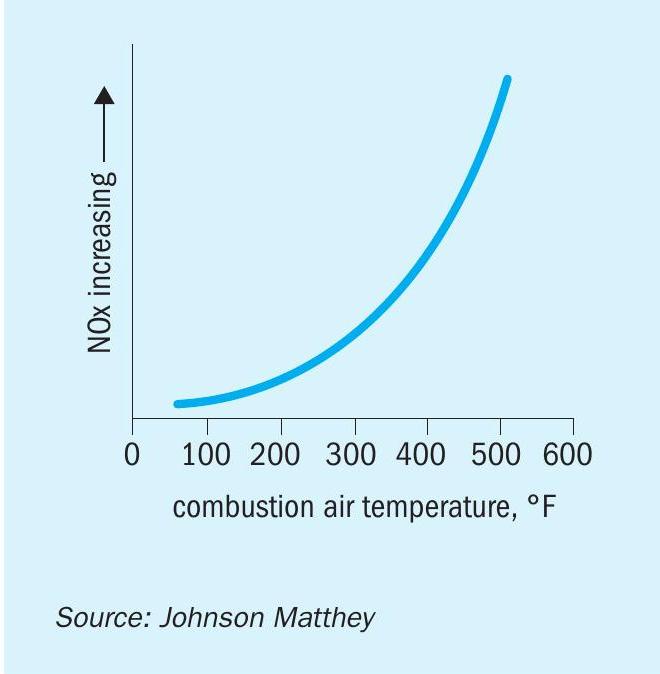
For steam methane reformers (SMRs) using gas-based fuels, thermal NOx is the primary contributor to overall NOx production, although levels can be increased further by contribution from any fuel-bound nitrogen such as purge streams that may be used as fuel containing ammonia (NH3 ). As combustion temperature increases there is a direct relationship with thermal NOx increase. Preheating the combustion air adds sensible heat to the flame reactants which increases the heat in the products of combustion and, thus, increases the flame temperature. Fig. 2 shows the effect of air preheat temperature on NOx. Note that the NOx essentially follows an exponential increase with increasing air preheat temperature. A rule of thumb is that the thermal NOx emissions will double as the combustion air temperature is increased from ambient to about 260-316°C (127-158°F).
To mitigate this burner designers can reduce overall NOx emissions by decreasing the peak flame temperature, which can reduce thermal NOx, these ‘low NOx burners’ typically work by delaying the rate of combustion. This is often achieved by either staged combustion, in which combustion air is added in two stages, or by designing the burner so that there is internal flue gas recirculation whereby the products of combustion are fed back into the combustion zone. Experience has shown that well designed low NOx burners can reduce the NOx levels to <100 ppm in a typical top fired reformer firing natural gas/hydrogen mixtures. Although ~50ppm is much lower than the NOx level from earlier generations of combustion technology it is still higher than that required for many regions where NOx emission levels of 5-10ppm are desired, meaning an SCR catalyst will be necessary, in addition to low NOx burner combustion.
Regulatory drivers for installing catalytic after-treatment
Concerns over air quality and its impacts have encouraged regulatory bodies across the world to impose limits and offer guidance to industry with respect to emissions of pollutants such as NOx. In the US the National Emission Standards for Hazardous Air Pollutants, NESHAPs rules are set to curb the formation of ground level ozone and in the EU the Industrial Emissions Directive (IED) aims to minimise pollution from various industrial sources throughout the EU. Both NESHAPs and the IED use a permitting mechanism to monitor and control. For the IED, for example, operators of industrial installations targeted by the directive – some 50,000 in total – have to obtain a permit from the authorities. The permit takes into account the whole environmental performance of the plant, including emissions, waste generation, raw material use and other aspects. The permit conditions under the current directives and the IED are based on defining the best available techniques (BAT). These are state-of-theart techniques that can be used to achieve a high level of environmental protection as a whole. They can be implemented in the relevant sector under economically and technically viable conditions, taking into account their costs and benefits. The issues related to increased levels of NOx and other pollutants in the air were recognised in the 1940s and since the 1960s significant steps have been taken to develop technology to limit such emissions at source. Most effective of these are catalytic after treatments, such as SCR, capable of removing more that 95% of NOx in gas stream. SCR is increasingly specified as a best available technology with the majority of the new methanol and ammonia plants being engineered for the “shale gas project wave” in North America all including an SCR system in the SMR system to reduce NOx emissions to the lowest possible levels of 5-10ppm. Increased concern and control of emissions means SCRs are now common projects in many regions including FSU, Middle East, China and Europe

How SCR works
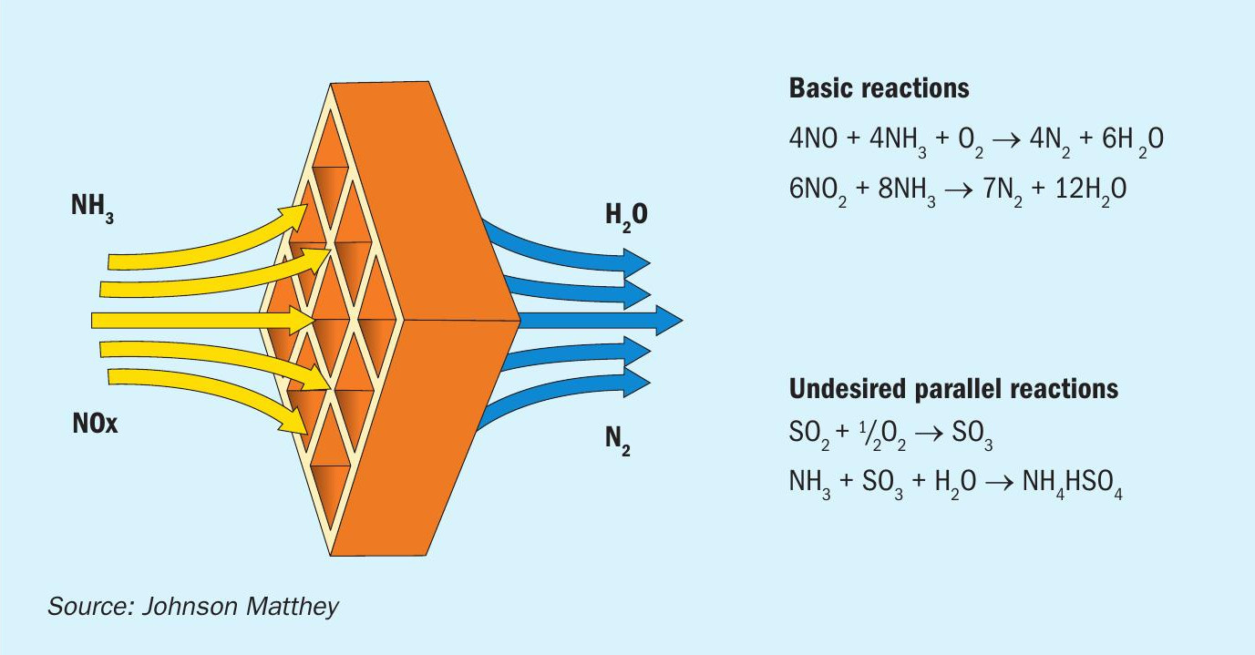
SCR is a relatively simple acid base reaction where ammonia reduces acidic NOx on the surface of a catalyst (see Fig. 3). This occurs at temperatures typically available in the exhaust gas, 250°C-450°C (482842°F).
NOx reduction occurs as the SMR flue gas/ammonia mix passes over the catalyst surface in the reactor chamber. Before entering the catalyst chamber, ammonia is injected and allowed to mix with the exhaust gases. The chemical equation for a stoichiometric reaction using either anhydrous or aqueous ammonia for a selective catalytic reduction process is:
- 4NO + 4NH3 + O2 → 4N2 + 6H2 O
- 2NO2 + 4NH3 + O2 → 3N2 + 6H2 O
- NO + NO2 + 2NH3 → 2N2 + 3H2 O
Secondary reactions include:
- 2SO2 + O2 → 2SO3
- 2NH3 + SO3 + H2 O → (NH4 )2 SO4
- NH3 + SO3 + H2 O → NH4 HSO4
When urea is used as the source of the reductant, (not the norm in the chemical industry application of SCR), the reaction is
4NO + 2(NH2 ) 2CO + O2 → 4N2 + 4H2 O + 2CO2
The NOx abatement reaction has an optimal temperature range between 357 and 447°C (675 and 837°F), but can operate from 227 to 447°C (441 to 837°F) with longer residence times. The minimum effective temperature depends on the various fuels, gas constituents, and catalyst geometry.
Given the operating temperature range of 250-450°C (482-842°F) in a steam methane reformer, the location where the SCR system will be typically located is at the end of the flue gas duct immediately before or after the air preheater.
High efficiencies typically over 95% have been reported, in order to achieve successful reduction in NOx a number of factors need to be taken into account, particularly the uniformity of the mixing of the flue gas stream with the reductant, typically an ammonia mixture which is injected across the flue gas duct using an ammonia injection grid (AIG). During the design process by the use of CFD modelling an analysis of the flow regimes can be made to ensure that the quality of mixing is of sufficient quality.
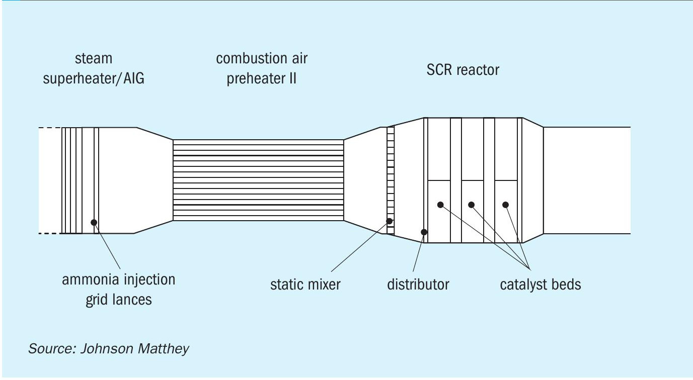
Fig. 4 shows the scope of CFD analysis of a flue gas flow from the AIG positioned immediately downstream of the steam superheater coil, a static mixer to complete the mixing process and reduce temperature variations upstream of the SCR catalyst.
As a result of the CFD study, Fig. 5 shows the ammonia-air mole fraction on a vertical plane through this section of the flue gas duct, from the AIG in the left through the combustion air heater and the mixer before the SiNOx catalyst beds.
After the static mixer the flow into the SiNOx SCR catalyst bed was demonstrated to be very well mixed with a uniform velocity.
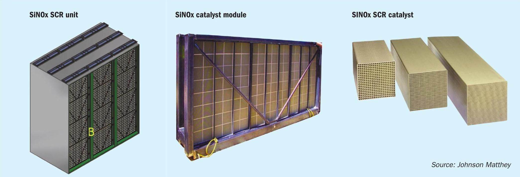
The catalyst is formed as extruded monoliths, which are arranged in modules which form the SiNOx SCR unit (Fig. 6).
The extruded monolith catalyst structure gives a very high specific surface area for a low pressure drop, the monolith catalysts are available in various lengths and number of cells, with the size and shape of the catalyst modules are selected to meet the project specifications for pressure drop and expected life.
Efficiencies of above 90% are typical and efficiencies of over 95% have been reported. In order to achieve years of successful reduction in NOx emission a number of factors need to be taken into account:
- flow rate;
- NOx in/NOx out;
- temperature;
- pressure;
- poisons;
- NH3 slip;
- sulphur;
- pressure drop.
The operation of SCR technology, including the sizing of the reactor, needs consideration of a number of different, sometimes opposing, factors. The desired or required limits for NOx and unreacted ammonia emissions, (referred to as ammonia slip) are fixed and factors such as pressure drop have to fall within acceptable parameters. There is an element of trade off or compromise in catalyst and reactor design and the space available and the time of operation (interval before servicing/shut down) are additional concerns. In operation blocking or poisoning of the catalyst is of critical concern.
SCR technical issues and their resolution
Catalyst pores can be blocked/plugged by material present in the exhaust stream. Examples include particulate material, (e.g. refractory ceramic fibres), ammonium bisulphate salts (ABS) and silicon compounds. Many can be removed when the unit is in operation, for example by dust blowers. For the case of ABS, the catalyst and system can also be regenerated or cleaned by raising the exhaust temperature. Of greater concern for SCR performance in the chemical industry (such as SMR) are poisons, which will disrupt/modify the chemistry of the catalyst and render the SCR ineffective or worse, affect oxidation of ammonia (forming more NOx). Some of these poisons include: halogens, alkaline metals, arsenic, phosphorus, antimony, chromium and copper. Of these poisons it is chromium in particular that is a feature of SMR operation.
In recent years the effect of water vapour on the volatilisation of chromia has been studied:
Cr2 O3 (s) + xO2 (g) + 2H2 O(g) → 2CrO2 (OH)2 (g)
Depending on the plant design there are different fuel compositions, for example higher hydrogen purge gas which can be routed to fuel. In these plants the level of hydrogen in the fuel directly impacts the percentage water vapour present in the flue gases.
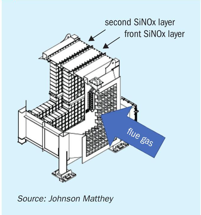
Volatilisation occurs at rates in partsper-billion (ppb) or less from the SMR reformer catalyst tubes in the radiant section. Awareness of SCR catalyst chromium poisoning is factored into the SCR design (Fig. 7) providing additional catalyst volume in the design to compensate for the Cr-poisoning rate anticipated, plus the SCR system can be designed to help management and monitoring, such as including sample coupons and designing the catalyst bed as layers so that the front section of the bed which is most impacted by Crpoisioning can be changed out more often if it becomes poisoned.
Effect of SCR catalyst design
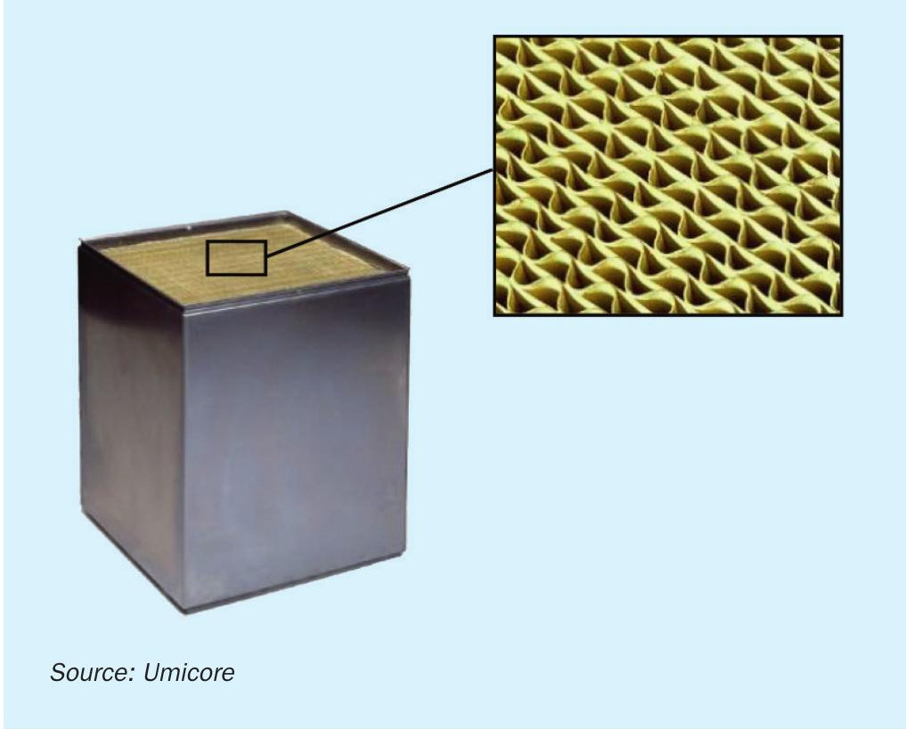
The number one priority from a utility point of view is to reduce the total catalyst volume as much as possible when reducing emissions from a steam methane reformer or other refinery unit. This will save both pressure drop and space in the convection section, but with emission requirements getting more and more stringent it is often a difficult task. The emissions are often reduced by installing a catalyst in the convection section, preferably at temperatures between 250°C to 380°C (480°F to 715°F), while adding ammonia to the flue gas stream upstream. So finding space in the correct temperature window is often a challenge. The SCR catalyst is normally supplied in elements that can be built to modules of any size (Fig. 8).
During the design phase of the plant it is often tempting to go with low catalyst pitch as this will reduce overall catalyst volume but also reduce the footprint of the convection section. However, it may not be the right approach from an operational point of view.
Experience also shows that catalytic systems with smaller pitches tend to plug sooner which eventually will result in unplanned outages for cleaning or in worst cases replacing the catalyst to a type with a larger cell opening. When the latter is the case it is relevant to have the extra space available in the convection section to compensate for the reduced catalyst surface area because if not, it won’t be possible to fit in enough catalyst volume to provide enough catalyst activity to operate a full turnaround cycle and that again will result in premature outages or lower production rates by the end of the cycle.
Existing plants are commonly shielded to some extent from new and tighter regulations but that is not always the case. It is therefore becoming more common for licensors to involve Umicore in FEED studies of new plants to make sure enough space is available and the right catalyst defined from the beginning. Burner replacements/upgrades on existing plants may also have an impact and it is thus relevant to have some flexibility by sizing the catalyst correctly the first time.
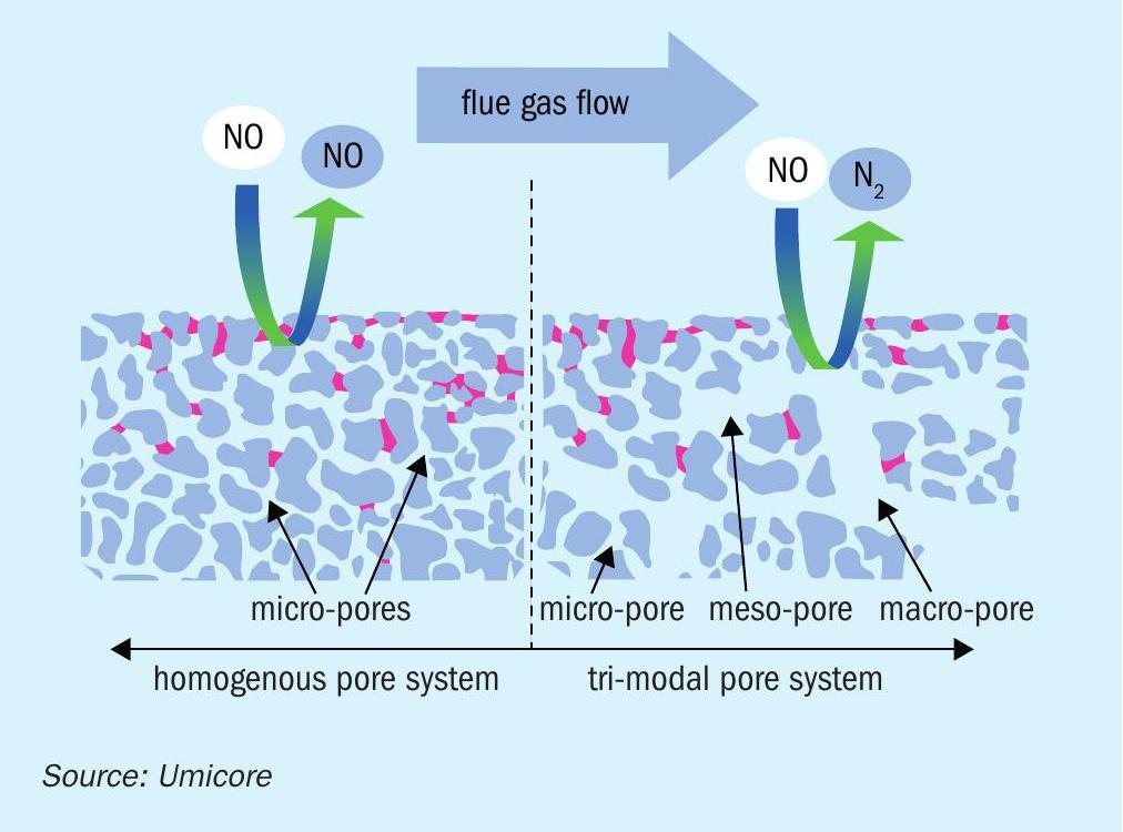
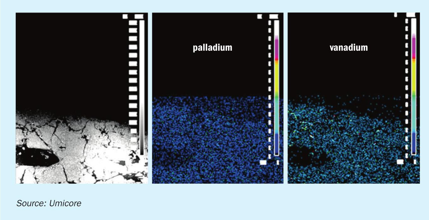
In some territories it is not only required to remove NOx with a low ammonia slip, but VOC and CO oxidation is also required from steam methane reformers or other refinery units. Umicore has developed a combined catalyst which reduces NOx while oxidising CO and/or VOCs. This is specifically beneficial when having a fixed reactor cross section for existing plants or having less space available in the convection section. In SMRs where chromium poisoning is a very well described challenge a porous catalyst structure will provide extended operational life compared to a typical wash coat oxidation catalyst. The reason is that chromium will not be able to block the flow in the macro pores but easily can sit on other catalyst surfaces without the larger pore system. Fig. 9 shows how solids or specific poisons can mask the catalyst if the catalyst type is incorrectly chosen and doesn’t have a tri-modal pore structure. Both the active ingredient for the SCR reaction (vanadium) and the active ingredient for the oxidation reactions (palladium) are homogenously distributed across the catalyst wall and here illustrated by the WDS (wavelength dispersive X-ray spectroscopy) intensity maps (Fig. 10).
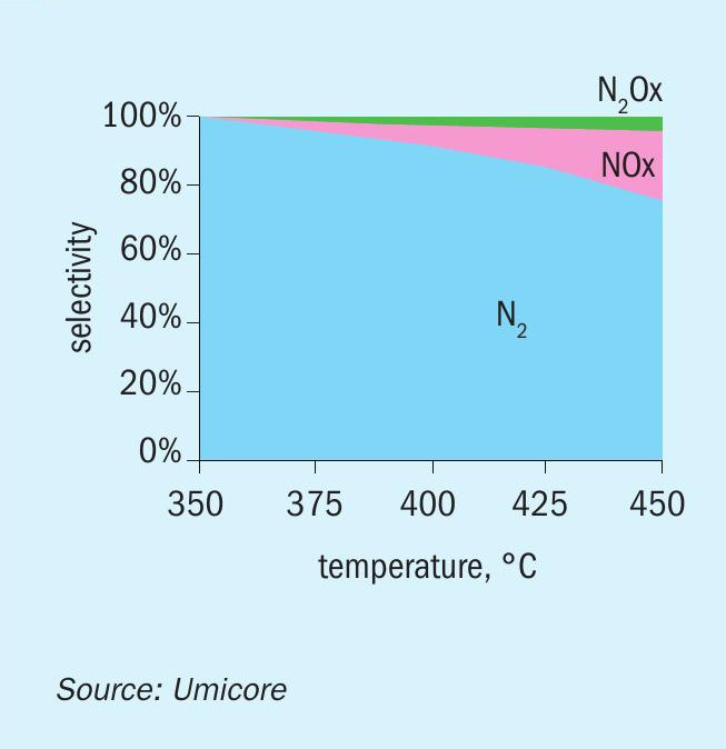
From an operational perspective the only drawback of using a combined catalyst is a slight increase in ammonia consumption. The actual ammonia consumption rate is normally defined by a mass balance that considers flue gas flow rate and NOx content (and required NOx reduction rate) but since Umicore’s dual function catalyst is so efficient it may also oxidise remaining ammonia from the SCR reaction. It is possible to differentiate the dual function catalyst into multiple zones within the same catalyst bed with a standalone SCR catalyst part and the remaining part a dual function catalyst. The advantage by doing this is that the concentration of ammonia is reduced drastically at entrance to the dual function catalyst part, and also the investment cost is reduced since the cost of the DeNOx part is lower than the oxidation part which contains noble metals. Since the dual function catalyst (the last part of the bed) is supposed to both oxidise CO/VOCs and reduce NOx in the typical SCR reaction, some NH3 will be present here. Some of the ammonia may get oxidised and it is therefore relevant to look at the oxidation product and selectivity of the oxidation process. Fig. 11 demonstrates the selectivity of ammonia oxidation over the dual function catalyst at 25-50 ppmv concentrations of NH3 . As is clearly seen in the plots, very little to no NOx or N2 O emissions are measured after the catalyst at temperatures below 370°C (700°F).
The manufacturing process has been optimised so the typical SCR catalyst is impregnated in an additional step with palladium. A proprietary process applies the palladium very uniformly near the surface of the catalyst. The process requires only a small quantity of palladium to achieve a very high CO oxidation rate. Less palladium means lower NO oxidation, lower SO2 oxidation, and lower NH3 oxidation. The dual function catalyst has already been installed in a number of SMRs as well as other refinery units.
SNCR application in a down-fired steam methane reformer
Changes in NOx emission limitations in the Middle East have required producers to find ways to retrofit NOx reduction technologies into existing furnaces. In Qatar, the NOx limit was reduced to 125 mg/m3 . While this is not a difficult number to achieve for a new furnace, attaining this value in an existing high temperature furnace poses challenges.
One of BD Energy Systems’ customers operates a large down-fired methanol reformer with a radiant section flue gas exit temperature (bridgewall temperature) of approximately 1,000°C (1,832°F). Previous issues with thermal cycling in the reformer were successfully addressed by modification to the burners. Additionally, mechanical issues suffered in low NOx burners had been a problem.
For existing high temperature furnaces there are four basic options that were considered for reducing NOx. The first considered is operational changes to reduce temperatures of the radiant section and targeted maintenance to address air infiltration, particularly in the radiant section. This method is usually the low-cost option but the reduction attainable is limited.
Changing the burners to a design that produces less NOx is often one of the best options. Newer Low NOx burners are capable of limiting NOx emissions to well below 125 mg/m3 on a wide range of fuels and at high bridgewall temperatures. However, the technologies that reduce the NOx necessarily produce changes in flames. Characteristics such as burner spacing, flame shape and size, heat flux, etc. must be carefully considered to assure that the process is not limited, or the furnace adversely affected. For these reasons, this method was considered too risky for this reformer.
Another method of NOx reduction considered was selective catalytic reduction which can be designed to achieve high levels of NOx reduction that can be easily guaranteed. SCR presented several disadvantages for this reformer. The most significant was that the existing ID fan was already very large and capacity limited. Another issue is that SCR requires specific temperature ranges to be most effective. In this case it would have required significant modification to the convection section to make the required space available at the right temperature range. This would have been costly and taken considerable install time. A final concern was that fouling of the catalyst with atmospheric dust brought in through the FD fan could be problematic without installing a filter. This could have limited the FD fan.
Selective non-catalytic reduction (SNCR) is an alternative system that has not been typically used for high temperature furnaces, as the requirements for a successful installation are difficult to meet. One of those requirements is the appropriate temperature range. If the temperature is too low, the reaction is too slow, and there may not be sufficient reaction time, resulting in unreacted ammonia (ammonia slip) out of the furnace stack. Too high a temperature can result in relatively high ammonia consumption and an actual increase in NOx!
Generally, bridgewall temperatures of 980°C to 1,040°C can be considered candidates for an SNCR system provided good mixing can be achieved and there is adequate residence time available. Once the flue gases enter the convection section rapid cooling makes the reaction too slow to be effective. This can result in ammonia slip occurring. The allowable ammonia slip is also regulated in many areas. At higher temperatures a higher ammonia to NOx ratio is required to achieve the desired reduction. As temperature increases, the amount of ammonia converted to NOx increases instead of reducing. This can result in SNCR being economically unsatisfactory, ineffective in reducing the NOx, or even increasing the NOx.
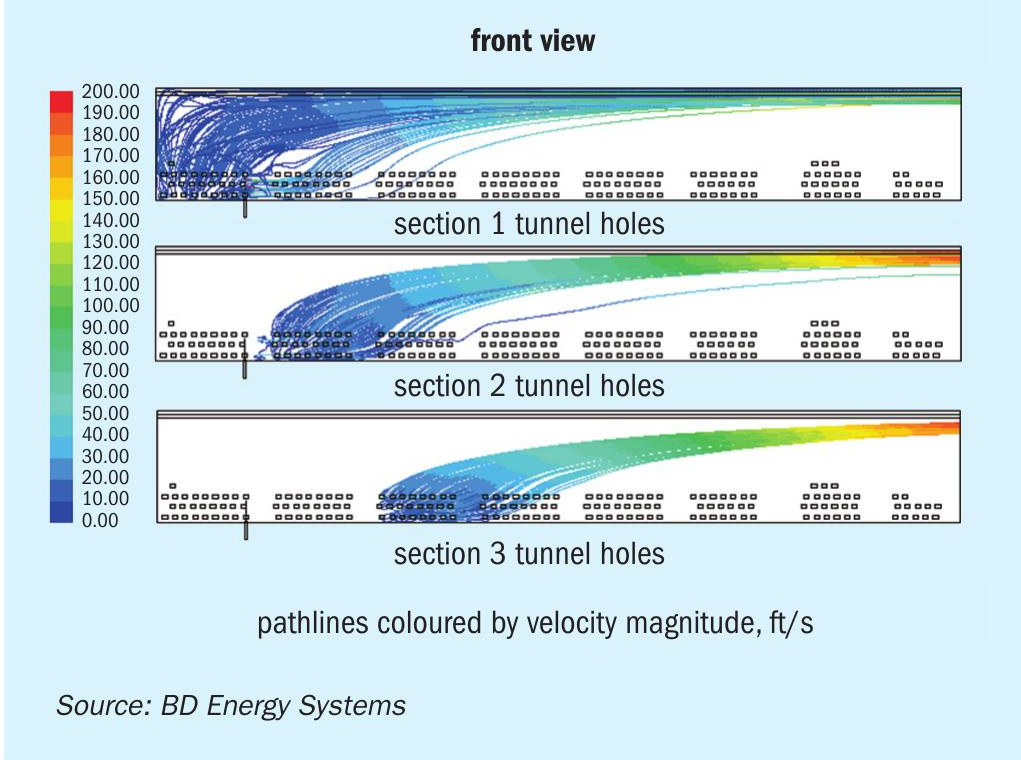
Adequate mixing is critical to achieve effective NOx reduction and minimal ammonia slip. Due to reformers’ large size radiant sections, reagent injection into the radiant section would require many injection points in the floor making for a cumbersome design. The typical flue gas tunnel design of a down-fired reformer with all the flue gas entering along the bottom of the tunnel causes stratification of the flow in the tunnel making good mixing difficult (see Fig. 12). Injection at the transition duct to the convection section can be practical but results in limited reaction time.
However, several CFD studies of the application of SNCR to this reformer were performed and it was determined that the conditions were well suited for effective SNCR performance. The size of this reformer provided a long transition duct, the temperature range considered was suitable, and rapid mixing was achieved through injection at carefully placed spray nozzles.
This SNCR installation had the added advantage that it required only minor modification to the reformer. Most of the work to install the system could be done ahead of time while the unit was in operation, requiring only a normal outage to make the final tie-ins to complete the system.
Selection of the reduction agent, urea, anhydrous ammonia, or aqueous ammonia was an important consideration for the design of the system. All three have advantages and disadvantages to consider such as safety, supply availability, storage and handling system, and injection characteristics. Anhydrous ammonia was eliminated as a choice due to significant environmental and safety concerns. Urea was eliminated due to concern about injection nozzle fouling and additional reaction time required. Aqueous ammonia solution (19%) was selected as the reagent for the system design. This had the advantages of being relatively safe, readily available, and suitable for the injection method designed.
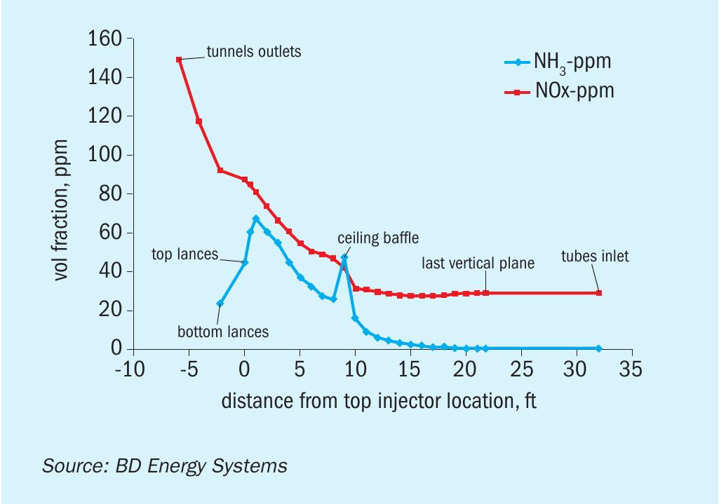
Having determined that SNCR was suitable and after choosing the reagent, computational fluid dynamic modelling (CFD) was performed to predict performance and optimize the design sufficiently to prepare a quotation for supply of the entire system. This involved selection of the reagent injection locations and pattern based on mixing and residence time. With several design iterations the system was optimised for performance (see Fig. 13).
A technical and commercial offering was then presented to the customer and accepted. Detailed design and supply of the complete system then commenced. The supply and installation of most of the system components were completed before the next planned outage. During the outage, installation of the injection nozzles into the reformer and the final tie-ins took place without issue.
After start-up of the reformer the SNCR system was commissioned and put into service as planned. The system easily brought the NOx down to the required level, with room to spare for further reduction. It was found that the results obtained in the field matched the predictions of the CFD analysis well.
It should also be noted that care was taken to identify and remedy areas of air infiltration into the radiant section. Air leakage in the vicinity of the burners can increase NOx produced and higher oxygen levels in the flue gas work against NOx reduction.
With careful consideration, an SNCR system is a proven technique to achieve NOx reduction as much as 50-60% in reformer furnaces, alone or in conjunction with other technologies.
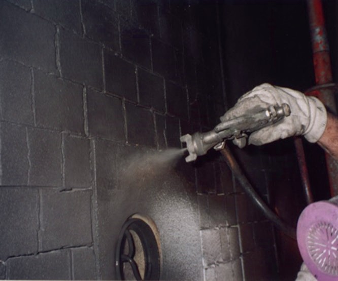
Emissions reduction using high emissivity ceramic coatings
Process heater environmental emissions reduction may be reduced without major investment or reconfiguration of the operating units by using high emissivity ceramic coating systems (Fig. 14). In a fired heater with low emissivity refractory surfaces, the radiation reflected from the refractory is readily re-absorbed by the flame and flue gases, superheating the flame and flue gases. The effect is to create a high level of NOx emission.
In a fired heater with a high emissivity ceramic coating, the re-radiated energy from the refractory surfaces is not readily absorbed by the flame and flue gases, eliminating the superheating and maintaining a relatively low NOx emission, up to 30% lower than a regular lining.
In gas-fired process heaters, etc. the CO2 emissions are derived purely from the combustion of the hydrocarbon fuel. From the use of Cetek’s high emissivity ceramic coatings, radiant section heat transfer efficiency may be significantly improved, providing up to 5% fuel savings and hence the same degree of CO2 emission reduction.
Refractory surface emissivity
In the radiant section of the tubular reformer, much of the radiant energy from the flame/ flue gas is transferred directly to the process/catalyst tubes; however, a significant proportion interacts with the refractory surfaces. The mechanism of this interaction has an appreciable effect on the overall efficiency of radiant heat transfer. A major factor in determining the radiant efficiency is the emissivity of the refractory surface.
At process heater operating temperatures, new ceramic fibre linings, for example, have emissivity values of around 0.4. Insulating fire brick (IFB) and castable materials have emissivity values around 0.6. These materials have been designed with structural considerations and insulating efficiency as the primary requirements. They tend not to handle radiation in the most efficient way. Cetek ceramic coatings, however, with emissivity values of above 0.9, have been designed specifically to supplement the radiation characteristics of the refractory surfaces.
How surface emissivity affects heat transfer efficiency
It is important to understand how the emissivity property of a surface can affect the efficiency of heat transfer. There are two factors which need to be taken into account. The first is the spectral distribution of the radiation absorbed/emitted from a particular surface and the second is the value of the emissivity of that surface. The amount of heat, Q, radiated from a surface (area, A; temperature, T; emissivity, ε) is given by the following, well-known Stephan Boltzman equation:
Q = AεσT4
Where σ is the Stephan Boltzman constant.
Lobo & Evans (1) and others extended the calculation with reference to fired heaters and a simplified equation would appear as:
QR = Aσ(T1 4 – T24 )/F
Where
F = 1/ε1 + {A1 /A2 }{(1/ε2 ) – 1}
for tubes of area A2 , surface temperature T2 and emissivity ε2 are inside an enclosure, area A1 , with surface temperature T1 and emissivity ε1 .
The effects of maximising the emissivity ε1 of the enclosure are obvious; there is a significant increase in radiant heat transfer to the tubes. As stated earlier, much of the radiant heat to the tubes travels directly from the flame/flue gas, but the emissive property of the refractory surface has a profound effect.
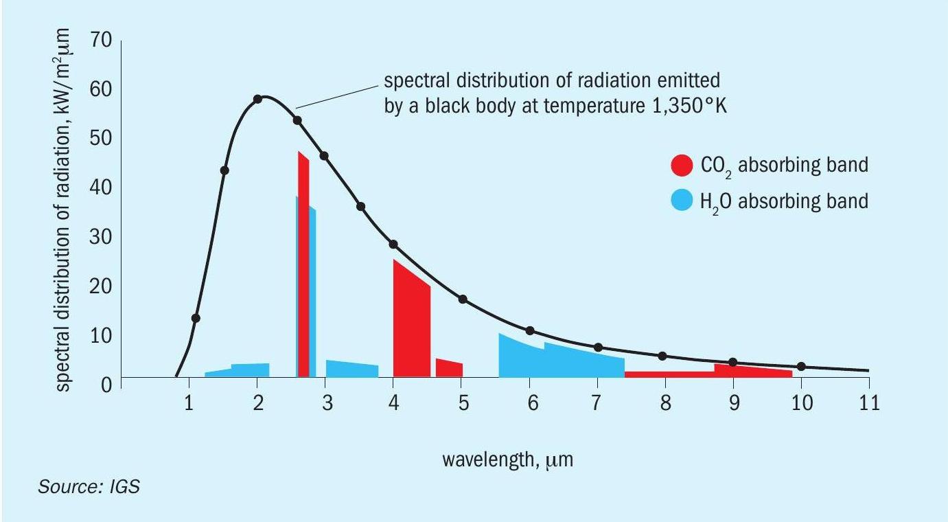
The chart in Fig. 15 shows the energy spectra for two major components of the combustion products of natural gas; water vapour and carbon dioxide. They are compared with the spectrum of a perfect radiator, or black body, at the same temperature.
The combustion products will radiate and absorb energy in the narrow wave bands shown, whereas a black body will radiate and absorb energy over a much wider wavelength range.
High emissivity surfaces are able to radiate energy across a broad wavelength band lessening the interference of the CO2 and H2 O in the flue gas.
What is a black body radiation?
When the radiation from a flame strikes a perfect radiator, all the energy is absorbed and re-radiated, but most importantly, it is transformed into “black body radiation”, as the wide waveband form. As the energy is re-emitted from the surface, it can penetrate the atmosphere in the furnace, composed of the combustion products, with little being reabsorbed and taken to the stack by the draft. Therefore, it is more readily available to heat the load in the furnace.
If the surface were a poor radiator, or one having a very low emissivity value, the energy striking the surface would be reflected back from the surface still in its untransformed state, therefore more readily absorbed by the furnace atmosphere. The effect is to “super-heat” the furnace atmosphere, or flue gas, resulting in wasted energy lost to the stack.
Reduction in flue gas temperature and heat transfer efficiency
The improvement in radiant heat transfer efficiency naturally leads to a reduction in flue gas temperature. This has consequences in the convective heat transfer in both the radiant and convection sections of the fired heater. In the convection section, heat in the flue gas is used to produce steam and preheating of combustion air and often process fluids. The heat transfer/absorbed duty balance should be examined closely to ensure that the balance is not adversely affected. There is also a contribution, though minor, from convective heat transfer in the radiant section, which may be characterised by the following equation:
QC = hC A2 (T1 – T2 )
Where hC , the film heat transfer coefficient, is an empirically derived factor related to the design of the radiant section and the tube configuration.
Steam methane reformer case study
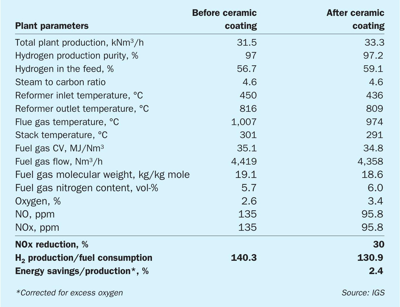
Table 1 illustrates the benefits following the application of high emissivity ceramic coatings to the refractory surfaces in a Foster Wheeler design hydrogen reformer.
The goal was to increase the throughput of the heater without increasing fuel firing, essentially debottlenecking the constraint. The application of Cetek high emissivity ceramic coatings had a positive effect on this heater. After coating, the unit was able to produce more hydrogen with less fuel input lowering costs and carbon emissions. Additionally, by reducing bridgewall temperature, Cetek ceramic coatings lowered NOx emissions by 30%.
References