Sulphur 393 Mar-Apr 2021

31 March 2021
Successful start-up of a new WSA plant
WET SULPHURIC ACID
Successful start-up of a new WSA plant
M. Baerends of Fluor reports on the conception, engineering, construction, commissioning and start-up of a new sulphuric acid plant that replaced an existing acid plant at a European sour gas processing terminal. This highly complex gas processing facility handles sour gas from an off-shore field, containing H2 S that must be removed to meet transmission grid specifications. Various issues encountered, their resolution by the joint owner, Fluor and Topsoe team, and plant operating results are discussed.
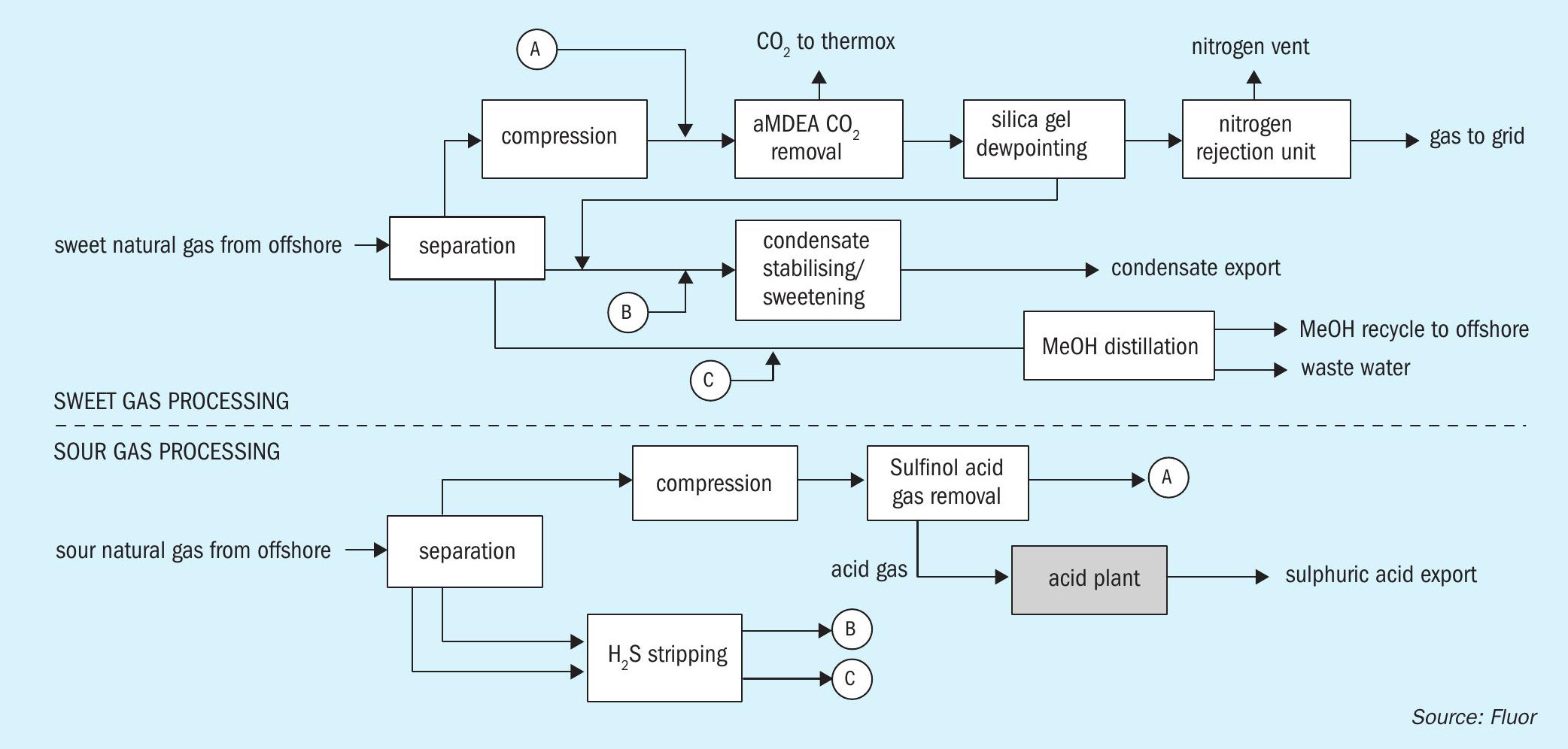
Overview of gas terminal
The gas terminal that is the subject of this article processes raw gas that is rich in both CO2 and nitrogen. This terminal was among the most complex in Europe when built, and includes compression, an activated MDEA (aMDEA) system for CO2 removal, a silica-gel type dewpoint bed system for water and heavier hydrocarbon removal, and finally a cryogenic nitrogen rejection unit (NRU) with associated deep dehydration and product gas recompression.
Further facilities include condensate stabilisation and caustic-based condensate sweetening, as well as a methanol distillation system for recycling methanol to the natural gas production fields (methanol being used as hydrate inhibitor).
The terminal includes two processing trains, one for sour gas processing and the other for sweet gas processing. Fig. 1 shows the two trains, and how they are linked.
Focusing on the sour gas processing train, feed gas enters a large separator-type slug catcher with overhead gas compressed by gas-turbine driven compressors from about 40 to about 80 bar. The compressed gas undergoes H2 S and mercaptan removal by means of Sulfinol treatment. As Sulfinol is a ‘hybrid’ chemical/physical solvent, it is well-suited to remove organic sulphur components such as mercaptans along with H2 S. Treated gas from the Sulfinol absorber is then routed to the sweet gas processing train where it enters upstream the aMDEA unit, subsequently passing through the silica-gel dewpoint beds and NRU systems.
Any liquids from the slug catcher are let down in pressure to a separator vessel in which hydrocarbon and water/methanol phases are separated, each liquid stream being directed to stripper columns in which H2 S is removed by fuel gas stripping. Overhead gas from these columns, together with flash gas from the Sulfinol system rich flash drum, is recompressed into the suction of the main gas compressors mentioned above.
Aqueous methanol liquor is routed to the water/methanol distillation in the ‘sweet’ gas processing train. Hydrocarbon condensate is also routed to sweet gas processing train for stabilisation and sweetening.
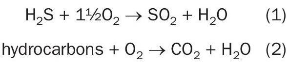
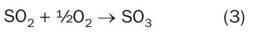
Acid gas from the Sulfinol regenerator is sent to the subject acid plant for conversion into sulphuric acid of 96 wt% ±2 wt-% concentration for export.
The utility system that supports the gas processing terminal is briefly described in so far as it is relevant to the project. The sour gas processing train has its own dedicated steam system, with steam generated primarily in the acid plant waste heat boilers, and consumed in the Sulfinol Unit for reboiling. Any excess steam is condensed in a trim condenser. Condensate from the trim condenser and Sulfinol reboiler is returned to a deaerator, augmented with demin water make-up, and pumped as BFW to the acid plant. An auxiliary boiler for start-up is also provided.
Acid replacement project
Engineering
Historically, the sour gas processing train operation, although generally successful, experienced issues related to the existing acid plant reliability. Eventually this led to a decision to replace the existing acid plant.
Fluor Ltd was contracted in to prepare a technology selection study for a replacement plant. The outcome of the study led to selection of the Wet gas Sulphuric Acid (WSA) process from Haldor Topsoe A/S. This process has been well proven in a range of applications and industries, from viscose production to metals smelting, coke oven gas, refineries and natural gas facilities.
Although a Claus-type sulphur recovery unit, followed by a tail gas treating unit (to achieve similarly low SO2 emissions) would have been a possible alternative, this would have required new infrastructure for exporting liquid sulphur, while an existing product acid export storage tank with truck loading facilities was already available. Furthermore, the acid gas design composition was very rich in hydrocarbons (including aromatics), in line with the use of a ‘hybrid’ physical/chemical solvent designed to remove mercaptans as well as H2 S. Processing an acid gas so rich in hydrocarbons (and also containing large amounts of CO2 ) in a Claus-type sulphur recovery unit might have been problematic. Finally, the capacity would have been on the lower end of capacity for a Claus unit.
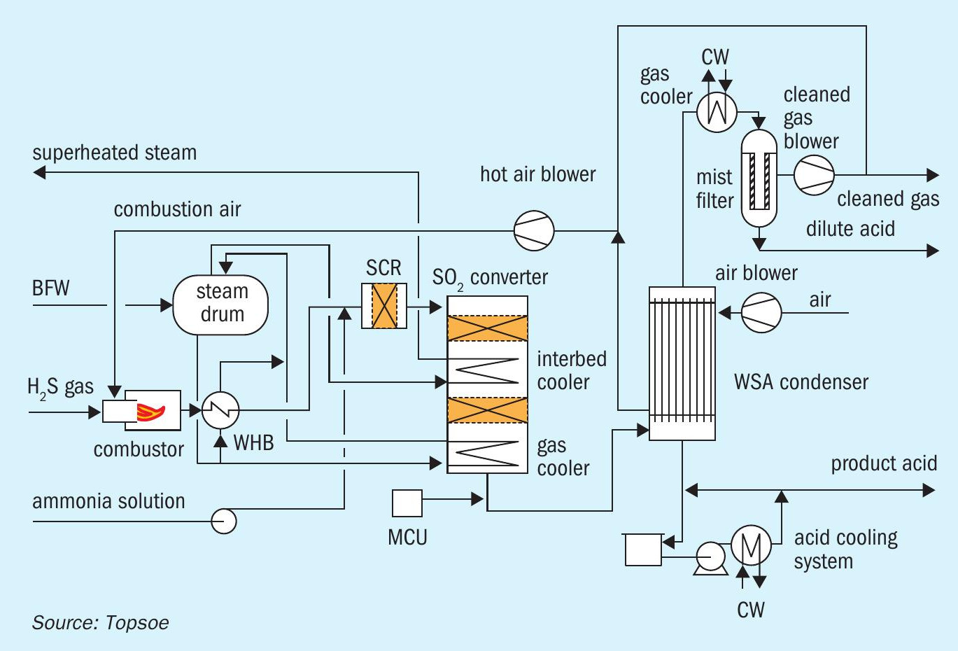
Fig. 2 shows a flow diagram of the process scheme for the WSA process.
Acid gas from the Sulfinol regenerator is combusted with an excess of combustion air in the refractory-lined combustor.
After heat removal by 50 bar steam generation in the waste heat boiler (WHB), a small amount of ammonia solution is injected into the process gas prior to a selective catalytic reduction (SCR) DeNOx step in which NOx is catalytically reduced to N2 . Gas from the SCR reactor enters the 2-bed SO2 converter in which SO2 is converted to SO3 by means of a proprietary vanadium pentoxide (V2 O5 ) catalyst.
The inlet temperature to the second bed is controlled using a coil that superheats saturated steam; the outlet temperature is lowered by means of another WHB at the converter outlet. In this WHB a large part of the SO3 reacts with water vapour to produce sulphuric acid vapour.
Gas from this WHB enters the proprietary WSA condenser in which the gas is cooled in glass tubes with cooling air on the shell side. Sulphuric acid condenses in the tubes and drops out to the acid vessel.
Condensation without excessive mist formation is promoted by the mist control unit (MCU) which adds a controlled amount of small particulates (condensation nuclei) to the gas. The concentration of particulates in the gas is important as both too high or too low concentrations of particulates in the gas can result in excessive mist formation.
The acid vessel, into which hot acid from the WSA condenser is drained, is cooled by means of acid circulation through a heat exchanger against a closed loop cooling water system.
Gas from the WSA condenser, substantially free of SO2 and sulphuric acid (barring a ppm-amount of acid mist) is further cooled after which it passes through a mist filter. Acid dropout in the mist filter is pumped intermittently to the combustor. Clean gas from the mist filter is passed to the stack by a blower. Combustion air is supplied by a blower that takes suction from the hot cooling air exiting the WSA condenser. The balance of hot air from the WSA condenser is routed to the stack for draft by means of temperature control, a slipstream is recycled through the cooling air blower to maintain a minimum cooling air temperature to the WSA condenser, with any excess vented to atmosphere.
In comparison with many other WSA plants, the acid plant is more extensive featuring DeNOx and an acid mist filter. Both provisions ensure a high environmental performance (low NOx and practically no acid mist emission).
Preparation of the licensor’s process design by Haldor Topsoe and Fluor’s front end engineering design (FEED) packages was followed by detailed engineering, procurement and construction also performed by Fluor from its Farnborough offices in the UK.
Construction
On site preparation work started prior to a scheduled shutdown of the sour gas processing train. During the shutdown, tie-ins were installed so that the existing acid plant could continue to operate whilst the new acid plant was being constructed and then isolated once the new acid plant had started up, eliminating interruptions to production.
Fortuitously, an empty plot was available on the site for construction of the new acid plant.
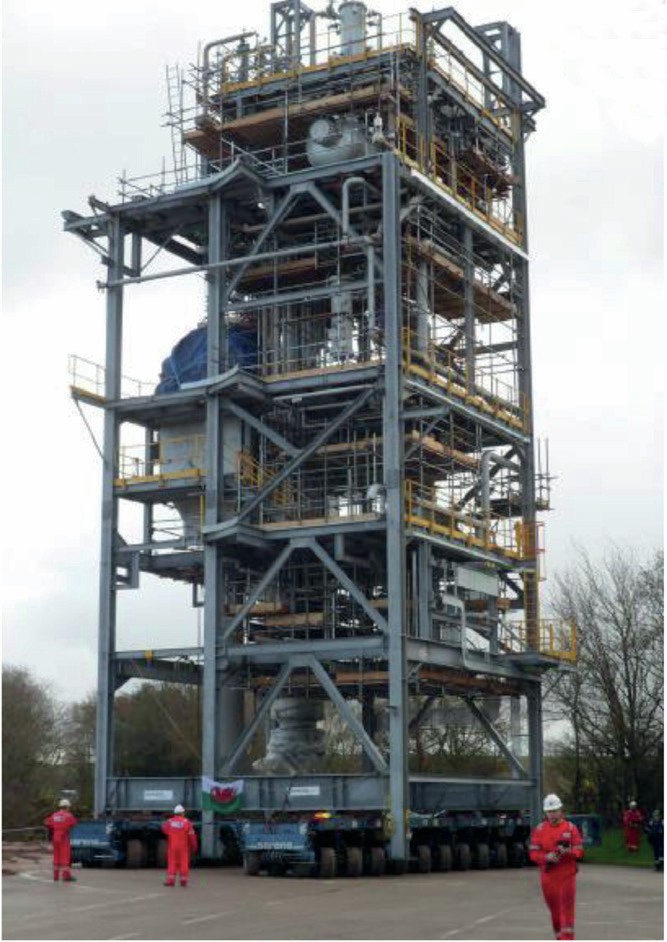
A philosophy of maximising off-site construction was followed using modularisation to a significant extent. Civil/structural sections were constructed in fabrication yards, then shipped to local docks and trucked to site. The largest section of the plant that contains the SO2 converter was shipped in sections to a temporary construction facility at the site, then the SO2 converter vessel was installed in this module, and the module was transported to its final location using a self-propelled modular transporter (SPMT); see Fig. 3. Other parts of the plant, where modularisation made less sense, were stick built.
(Pre)-commissioning
(Pre)-commissioning activities were started in parallel with the latter phases of construction. Pre-commissioning included the usual blowing and flushing, boil-out of the steam system, firing on fuel gas, refractory dry-out (both in the combustor and in the WSA condenser), and catalyst loading (performed by a specialised contractor).
Start-up and troubleshooting
Upon completion of construction and pre-commissioning, the actual start-up of the acid plant on fuel gas was initiated after inventorying relevant systems e.g. the product acid system with concentrated acid, the boiler water system and the acid mist filter with demin water. Much of plant operation was proven on fuel gas, as this operation mode requires most equipment to operate. This operation was to be followed by normal operation on acid gas.
A number of issues within the acid plant, and their resolution, are described in the following sections.
NH3 lance/pumps
One issue encountered was blocking of the NH3 injection lance through which aqueous NH3 solution is injected into the process gas for de-NOx purposes. The spray nozzle at the end of the lance features a very small opening and despite best efforts in terms of blowing lines, a blockage occurred requiring a shutdown during which the lance was pulled and cleaned. In order to prevent re-occurrence, a small duplex filtration system was fitted locally to the lance. This modification could be made very rapidly given the very small flow rate, which allowed the duplex filtration system to be made out of tubing.
This resolved the issue barring one more blockage caused by a shard of stainless steel material, almost certainly from the construction of the tubing itself.
Another issue around the de-NOx system was a mechanical problem with the reciprocating-type NH3 injection pumps. Sticky valves on the reciprocating pump cylinder (small ceramic balls) prevented the pumps from developing the required discharge pressure. This problem was fixed by the pump vendor who replaced the original ceramic balls with stainless steel balls.
With the lance blockage and pump issues fixed, performance of the de-NOx was excellent and NOx emissions are well within spec during normal operation. Only during initial start-up, when the catalyst beds are still being heated up (and NH3 injection is not allowed, to prevent any risk of ammonium salt deposits), NOx emissions exceed the limit for a very short time; on a time-average basis NOx emissions are very comfortably within specification.
Mist filter
A number of issues occurred around the acid mist filter system.
Initially, fairly rapid fouling occurred in the strainers in the dilute acid pump suction and discharge (the dilute acid pump moves acidic condensate entering the mist filter to the combustor). Some fibrous material emanating from the filter candles was found (loose fibres from the manufacturing process), as well as some other material that could not be easily identified. Since cleaning the strainers required a high level of personal protection (acid resistant suits) this was a concern. The filter candles were checked for breakages, and no problems were found.Furthermore, the filter candles were rinsed in-situ with demin water during an opportunity outage. As hoped for, this issue disappeared over time, and back-up solutions developed (i.e. more easily cleanable strainers) were not required.
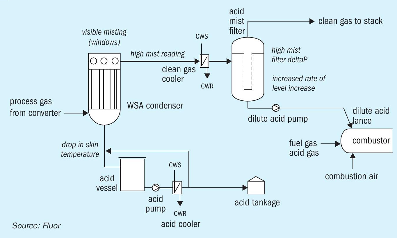
Another issue was a much higher than expected rate of accumulation of liquid (dilute acid) in the mist filter vessel. This was true both for fuel gas operation, and combined acid gas and fuel gas operation. Actual liquid ingress was up to 100 times higher than expected from the design material balances, even though the temperature of the process gas into the mist filter was well above the calculated water dew point and acid mist entrainment from the WSA condenser was nil or minimal. Initially, during fuel gas only operation, the high liquid ingress rate was not much of a concern, as the liquid was pumped intermittently to the combustor without any problems.
However, with the plant in combined acid gas and fuel gas operation, injection of dilute acid into the combustor resulted in an unexpected phenomenon (see Fig. 4). As soon as dilute acid injection started, a sudden and large increase in mist from the WSA condenser was observed (mist reading off-scale). At the same time, pressure drop across the mist filter elements doubled at constant gas flow (likely due to very high liquid loading). Also, the skin temperature on the acid drain line from the WSA condenser to the acid vessel dropped dramatically (indicating that hot acid was not running down but rather carried over into the mist filter). Most worrying of all, while pumping out dilute acid from the mist filter to the combustor, the mist filter level did not decrease, but kept increasing at an even higher rate than before. Eventually, after repeated attempts to stop and re-start dilute acid combustion, all with the exact same result, this situation became unsustainable and the plant was shut down in a controlled manner to avoid overfilling the mist filter (the result of which would have been dilute acid overflowing into the containment bund).
Investigation of this problem led to the following conclusions:
- Liquid ingress into the mist filter was high despite the gas temperature being above water dew point.
- Upon starting dilute acid injection to the combustor, massive misting in the WSA condenser resulted in carryover of acid that should drop out into the acid vessel into the mist filter (causing additional level rise).
The first phenomenon, the high rate of level increase in general, was attributed to localised condensation on the tubes of the clean gas cooler, with the liquid droplets not having the time to re-evaporate before impinging on the mist filter elements, even though the bulk gas temperature would indicate a dry gas. The high localised condensation hypothesis was supported by a very low cooling water temperature (10°C relative to the 33°C design value) as the closed cooling water system temperature control was not yet fully commissioned. When the cooling water supply temperature control (using variable speed fans on the closed cooling water air cooler) was rectified, and cooling water supply temperature was close to 33°C, a dramatic reduction in the rate of level increase was observed after re-start (from some 1.0%/hour level rise to 0.1%/ hour level rise, at constant bulk gas temperature), proving the above hypothesis.
As to an explanation for the second problem, observed heavy misting as soon as dilute acid combustion started, two main explanations were offered.
One explanation was generation of a large amount of solid particles in the gas to the WSA condenser, due to various contaminants in the dilute acid, for example fibres from the mist filter candles. This could have resulted in an excessive particulate concentration in the process gas to the WSA condenser, leading to high mist formation.
The second explanation was a blockage of the atomising air nozzles in the dilute acid lance, which could result in incomplete combustion of dilute acid. The blockage was found from atomising air pressure data (higher than calculated atomising air back pressure).
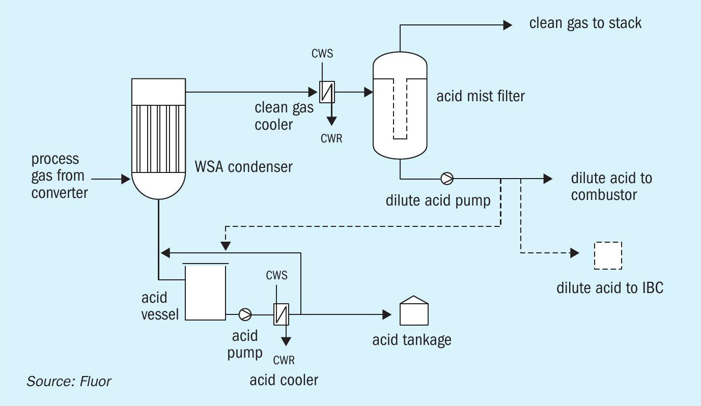
The above possible causes were addressed by a thorough cleaning of the dilute acid system, requiring opening of the mist filter, the contents having been emptied into 1-m3 plastic containers (intermediate bulk containers or IBCs), and by pulling the dilute acid lance, and removing the debris from the atomising air side of the lance and annulus of the nozzle.
Prior to re-starting, temporary alternative provisions were put in place to enable an alternative route of dilute acid disposal into IBCs through an acid resistant hose (Fig. 5).
Upon re-start, dilute acid was emptied into IBCs for a while, with full IBCs exported from site. The number of IBCs required was dramatically reduced by the above-described reduction in liquid ingress into the mist filter due to cooling water temperature control. Eventually the dilute acid combustion was re-tried. Interestingly, it was now found that the dilute acid injection actually reduced mist formation in the WSA condenser; this unexpected and favourable reduction was significant, reversible (stopping dilute acid injection increased mist again) and reproducible. With the design working again as intended, the route to IBCs was no longer required.
In order to have further flexibility, it was decided to add a provision to enable disposing of dilute acid into the acid export stream.
Needless to say such dilute acid disposal can have an impact on product acid quality with respect to strength, depending on respective flow rates of product acid (approx. 96 wt-%) and dilute acid (approx. 20-30 wt-%), and on product acid contaminants, particularly nitrogen containing compounds.
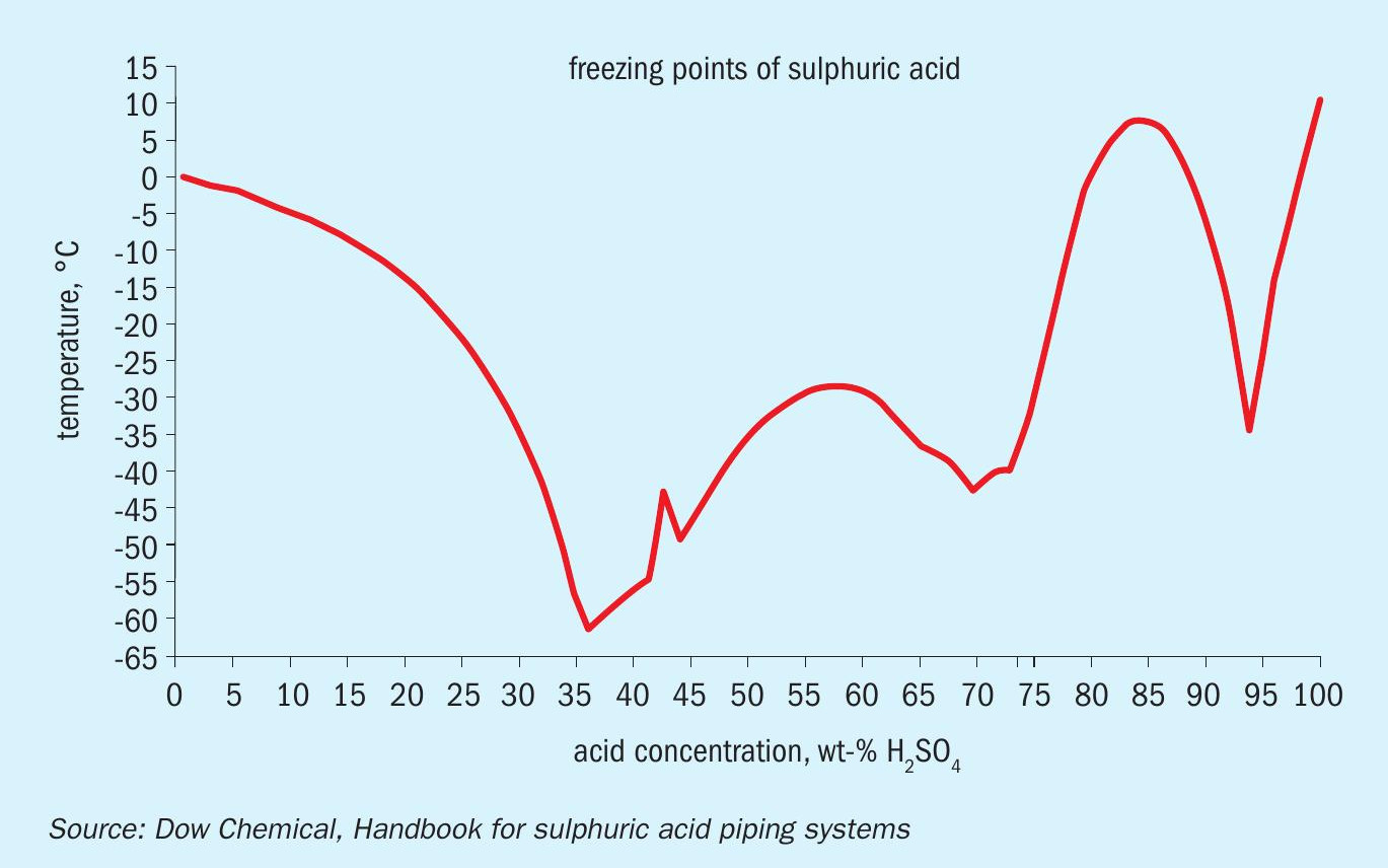
The limit on blending is that acid rundown strength should be > 91 wt-% approximately, so as to ensure a freezing point of the product acid less than the minimum ambient temperature of -10°C, as much of the export line is untraced (Fig. 6).
A temporary blending connection was made by means of an acid-resistant hose which was used for trialling blending. The main concern during trialling was the thermal effect of adding dilute acid into concentrated acid (enthalpy of dilution). The trials worked well, with very manageable acid temperature rise, at dilute acid blending rates more than sufficient to maintain stable mist filter level. A hard-piped blending connection will be added at a later time as a ‘back-up’ provision.
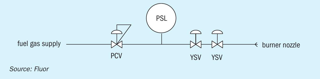
Pilot burner PCV
A fairly minor but irritating issue was experienced on the combustor pilot burner pressure regulator. Upon start of the pilot burner, the regulator could not maintain its downstream pressure. When this pressure dropped too much, the pilot burner would trip on low-low pressure (see Fig. 7).
This problem was permanently solved with a replacement of the pressure control valve (PCV).
Clean gas blower
The clean gas blower (CGB) takes suction from the mist filter and pushes the gas into the stack. The plant suffered a number of trips (thermistor) on the CGB motor. These trips only occurred after some 45-60 minutes of running the blower at maximum speed (caused by high gas flow, e.g. during combustor purge upon start-up or when operators increased combustion air to high values). What did not make sense is that the flow rate through the blower was well within the blower’s curve. With electrical data-logging equipment on line, a further trip was intentionally generated by ramping up the combustion air flow, showing that the kW, Ampere and torque were all within the motor and VSD system envelope. As such, the most likely explanation is a problem inside the motor. A new motor was purchased to be fitted on an opportunity basis. In the meantime, operations limited the combustion air flow (which sets the CGB suction flow) to about 75% of design which is fully sufficient to process the amount of acid gas available until the next shutdown. No further trips were experienced.
Stable operation
The above troubles were all resolved or managed. The concerted efforts of the integrated team (owner operators, Fluor, Haldor Topsoe and suppliers) were well rewarded with stable operation. The first weeks of the start-up had only limited periods of acid gas processing (minuscule level increases in the product acid export storage tank), for reasons both inside and outside the new acid plant. Needless to say this put considerable pressure on the team. However, with the teething troubles resolved, operation was steady and successful.
With stable operation, the generally very good performance of the plant already observed during the short periods of operation in the first weeks, did in fact materialise longer term.
The main parameter of the plant is sulphur recovery (conversion of SO2 into sulphuric acid) which was consistently above the 99.5% specification, resulting in SO2 stack levels far below the 400 mg/Nm3 permit limit.
Product acid quality was always comfortably within the guarantee value of 96 wt-% ± 2 wt-% .
Once issues with lance blockage and the NH3 pumps were fixed, DeNOx performance was excellent with NOx levels below 10 mg/Nm3 (permit 50 mg/Nm3 ).
Both for CO and H2 S, combustion residuals were low; CO around 2.5 mg/Nm3 , insignificant compared to the permit limit of 100 mg/Nm3 and H2 S 3-4 mg/Nm3 from CEMS, relative to 5 mg/Nm3 permit limit. The latter value from the CEMS was proven to be very conservative by manual sampling from the stack followed by lab analysis, which gave values close to the limit of detection.
The above was confirmed during the acceptance test run held at a few weeks after stable operation was established.
Acknowledgment
The author greatfully acknowledges Haldor Topsoe for the provision of Fig. 2 and wishes to thank all individuals involved in the project for their contributions.