Fertilizer International 502 May-June 2021
31 May 2021
Tailings filtration: Looking upstream to optimise the filter
FILTRATION & THICKENING
Tailings filtration: Looking upstream to optimise the filter
Filters can be a common bottleneck in overall plant operations. Jerold Johnson and Brad Bentley of WesTech outline how upstream modernisation or upgrades to the thickener can have significant benefits for the efficiency of filter operations downstream. Results are applicable to the dewatering of phosphate tailings and other fine particle tailings.
Filters are increasingly being used for the final dewatering of tailings. The dual benefits of water recovery and lower impoundment risks are making filtration equipment a more attractive option. Technology improvements, particularly larger filter sizes and higher pressure gradients, also means filters are becoming practical for dewatering phosphate tailings and other fine particle tailings.
There is a need to look at tailings dewatering operations as a whole, as improvements made upstream may have negative consequence downstream by changing the volume and characteristics of the tailings being produced. Increased tonnes-per-hour throughput, or even finer particle-size distribution, will adversely affect the filter.
Looking upstream for downstream benefits
Equipment upgrades and operational improvements can achieve several goals – identifying common bottlenecks in the dewatering stages being one of these. Typically though, optimising one bottleneck simply reveals the next one. While the filter stage can often appear to be a bottleneck, upstream thickeners – which affect the downstream filter – often provide greater scope and flexibility for optimisation.
Installed filters, once they reach capacity, can certainly limit overall plant optimisation. In these circumstances, turning attention upstream of the filters can yield significant benefits.
Filter sizing and capacity are based on dry solids throughputs (ex. kg*m2 /h). When optimising filters, however, attention should turn to the water volume in the feed. Indeed, models that predict filtration operations and filter rates show there is a clear potential for reducing filtrate volume1 .
For installed systems, the filtrate’s volumetric flow rate is a set parameter – for a given pressure differential and cake thickness. Consequently, reducing the water volume in the filter feed provides a direct reduction in the time taken for the filter cake to form. This reduction is beneficial to the design of greenfield plants as well as helping optimise existing operations.
It is the thickener upstream that dictates the hydraulic load on the filters. Therefore, improving control strategies, modernising the feedwell, and installing paste-type thickeners can all improve water recovery at the thickener – and ultimately benefit filters downstream.
Thickener modernisation
Thickener optimisation has been a focus at WesTech for many years. This has resulted in significant advances in feed-well design and bed level detection for thickener control.
Experience has shown that running the thickener with a constant solids inventory results in a predictable, steady-state operation. Allowing the bed level to rise and fall, in contrast, reduces water recovery by causing swings in the weight-percent discharge.
Underflow variations of just two percentage points, for example, could send eight percent water, or more, to the filter. Nevertheless, poor bed level detection methods in the industry have often limited the success of thickener control, forcing many plants to rely on manual control. Unfortunately, manual control is notorious for inconsistent operation.
WesTech recently introduced the Mud-Max™ – an instrument that directly measures the thickener bed level – to address this specific issue. The instrument’s sensor is mounted on the rake arms of the thickener, turning in sync with the mechanism2 . This instrument, by providing steady, accurate, continuous measurements, allows much greater thickener control. The target bed level is maintained using discharge pump speed as a control. This steady bed level gives confidence that operations are being optimised close to the thickener limits. Without swings in operation, the operational target for the thickener can be set much less conservatively. Instead, the thickener can be operated at deeper bed levels, resulting in greater weight percentage solids underflow. The thickener can also be confidently operated closer to torque alarms, with dewatering at an even greater dry tonnes per hour (tph) throughput as a result of this optimisation.
The heart of the thickener is the feed-well3 . Indeed, many of the poor thickener performance issues start here.
Yet conventional feedwells suffer from two glaring design flaws: short circuiting flows and poor mixing. That is generally because feed momentum is poorly managed in tangentially-fed feedwell designs. Consequently, large short-circuiting flows develop, prematurely exiting the feedwell and carrying with them poorly flocculated solids. This results in solids in the overflow and can produce uneven loading in the bed.
Feed momentum is still needed, however, as it is the source of energy for mixing in the feedwell. Most feedwell designs have a relatively small area where the mixing is optimum. This is often near the inlet, leaving the rest of the feedwell volume insufficiently mixed. This leaves the operator with only one recourse – increasing the flocculant dosage to try and compensate for these design flaws. The resulting overdosage in the thickener can be counterproductive as underflow density is reduced because the excess flocculant inhibits solids compaction4 .
Flocculation within the thickener must balance three objectives: clarity, settling rate, and the ability to compact. Proper flocculation also relies on dosage and mixing working well together. Any improvement in mixing, for example, reduces the dosage requirement.
WesTech introduced the EvenFlo® feed-well to address common feedwell issues. This feedwell design incorporates two stages. The first stage receives the feed stream, manages feed momentum and then directs the feed radially out into the second stage. This radial flow prevents short-circuiting and distributes solids evenly into the thickener. It also creates an optimal mixing zone around the entire periphery of the second stage feedwell. In summary, this simple design eliminates short circuiting and greatly improves the mixing needed for flocculation. The improved mixing significantly reduces dosage, improving operating costs and increasing the weight percent solids in the underflow.
Thickener types
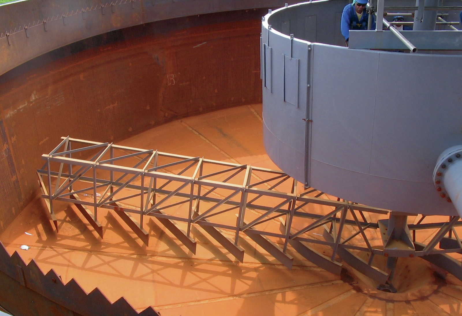
Not all thickeners are created equal either. Some designs produce a slurry underflow, such as high-rate thickeners (HRTs). Other designs produce non-Newtonian (significant yield stress) underflow, like the high-density paste-type thickeners (HDTs). Both thickener designs are commonly used in combination with filters. Recently, however, the HDT type has emerged as the thickener of choice.
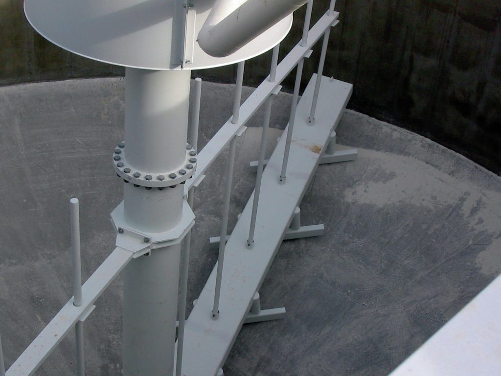
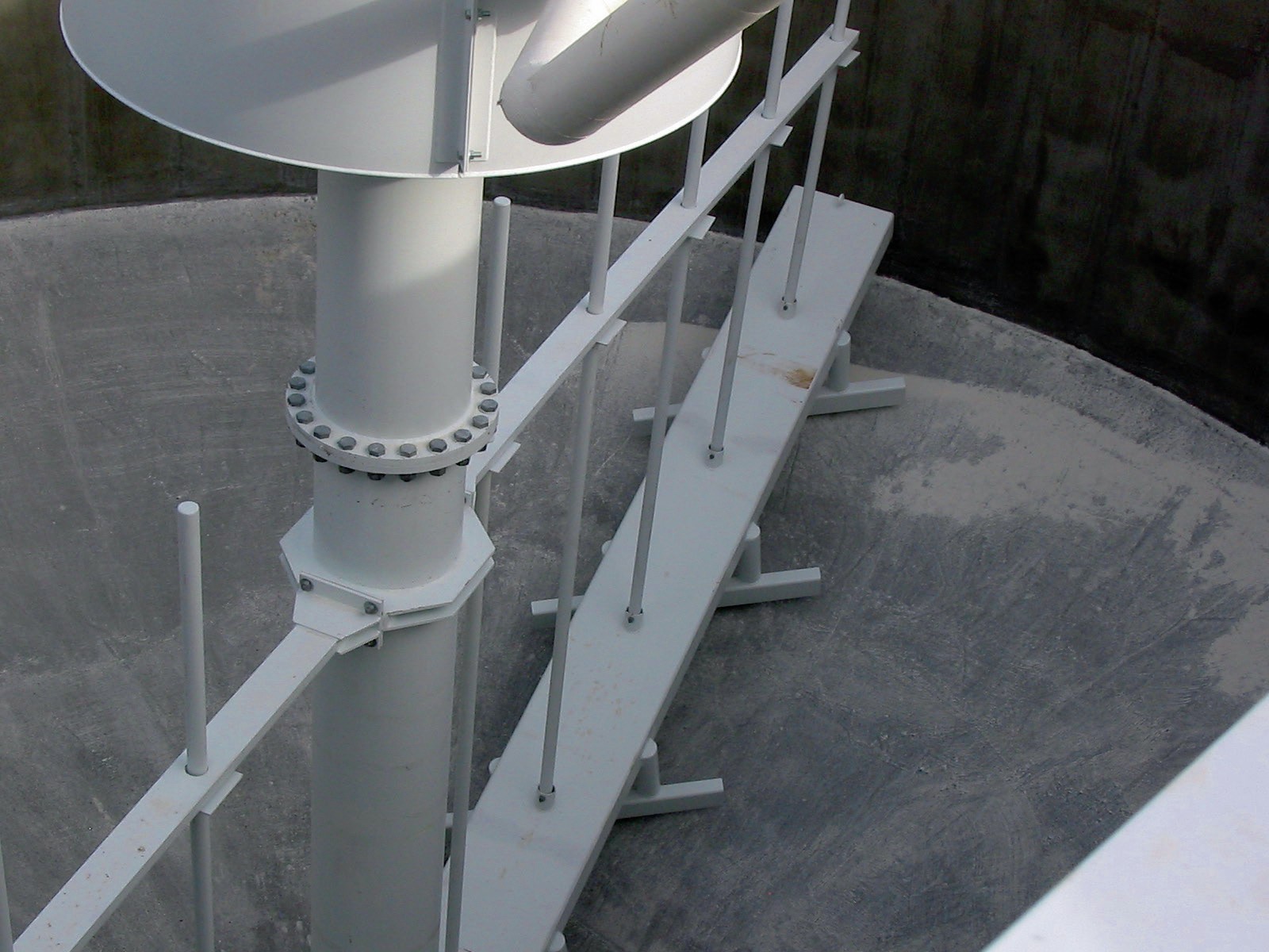
HDTs differ from HRTs in terms of mechanism design, floor slope, drive torque, and tank dimensions (see photos). HDTs, with their low-profile mechanism with dewatering pickets and high torque drives, are designed to produce and discharge the non-Newtonian underflow. Advantageously, the HDT will produce a greater weight percent solids underflow, yielding a 15 percentage points increase or higher.
Differences in the weight percent solids obtained by a HRT and a HDT can be compared in case studies where these two thickeners dewater the same material as part of a two-stage thickening process. Full-scale installations initially use HRT to dewater plant tailings. This saves on pumping costs due to the smaller volume of HRT underflow obtained, relative to the total tailings volume. The HRT underflow is next pumped, sometimes over long distances, to a HDT located at the tailings storage facility. The HDT then completes the final dewatering needed to enable the tailings to be surface stacked.
The two thickeners dewater the same solids and, in both cases, the slurry must be diluted to optimal feed concentration with the solids then flocculated. Data from mine sites reveal that the HDT recovers more water, producing an underflow with 40 percent less water present, compared to the HRT underflow.
HDTs also meet a key requirement for the filter feed, i.e. it is fluid enough to fill the filter chamber or spread easily over the filter cloth. Valuably, HDTs are designed to produce a low yield stress underflow that is still fluid and easily fills the filter chambers or spreads on the cloth.
Benefit of reduced water in the feed
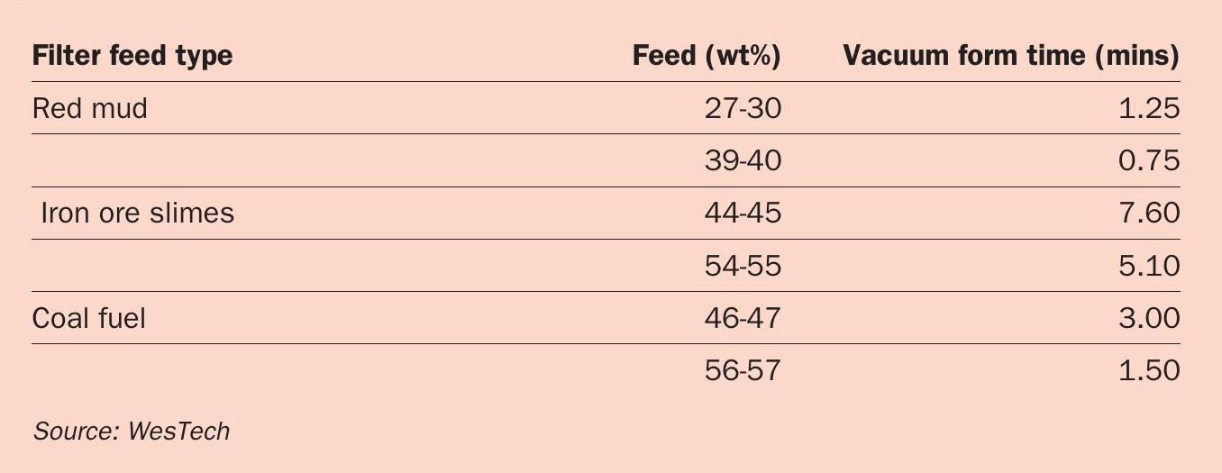
Reducing the water content of the feed shortens the filter cake form time in the filtration cycle. Table 1 demonstrates the benefits of this for phosphate and other fine particle tailings. It provides a comparison between weight percent solids in the filter feed of red mud, iron ore slimes and coal fuel tailings. These are all known for their fine particle-size distributions. For each type of tailing, the form times from vacuum filter bench-scale leaf tests are shown for two different feed concentrations. Results demonstrate that form time was reduced due to a higher solids weight percentage of about 10-percentage points By reducing the water in the feed, the form time was in fact reduced by around 36-50 percent.
Filters can be a common bottleneck in the overall plant operation. The form time in the filter cycle is particularly dependent on the volume of water that needs to be removed. A cost-effective way to optimise the filter, therefore, is to optimise the thickener preparing the filter feed. Consequently, modernising or upgrading the thickener, as described in this article, can have significant benefits on the filter operation. This applies to the dewatering of phosphate tailings and other fine particle tailings.
References