Sulphur 394 May-Jun 2021
31 May 2021
The key to acid quality and acid plant longevity
WET GAS CLEANING
The key to acid quality and acid plant longevity
With declining ore grade feed to a metallurgical smelting process comes an increase in impurity load in the gas cleaning/acid process chain. K. Hasselwander, L. Skilling and C. Bartlett of Metso Outotec discuss a range of process solutions and how to maintain high productivity while keeping costs in check.

In order to enable the continuous production of sulphuric acid, the gas must be thoroughly cleaned. All inorganic matter, which could contaminate the acid or have an impact on plant operation by decreasing the plant availability, must be removed from the gas.
A wet gas cleaning system design must take into account the dynamic conditions of the operation of the upstream installations. Gas treatment systems for metallurgical furnaces releasing SO2 containing gases usually consist of a gas cooling and hot gas dedusting system followed by a wet gas cleaning system. This article will concentrate on the wet gas cleaning train.
Gas cleaning can often be overlooked, with no second thought or concern on its operation or condition. However, it is integral to overall plant efficiency, and it is a big mistake to think otherwise. To ensure that your plant is in the best condition for the future, you need to keep your gas cleaning facility in peak condition. Though different alternatives may seem feasible in the short term, a plant needs reliable and productive equipment to maintain operation in the long run. Metso Outotec has the capability to deliver high quality, tailored solutions and ensure flawless plant operation.
“When making statements on increasing impurity loads, it is important to keep in mind the underlying causes for the change,” says Leif Skilling – Director, Gas Cleaning Product Group at Metso Outotec. “These will no doubt have immense future implications for our industry and it’s time we start seriously considering them.”
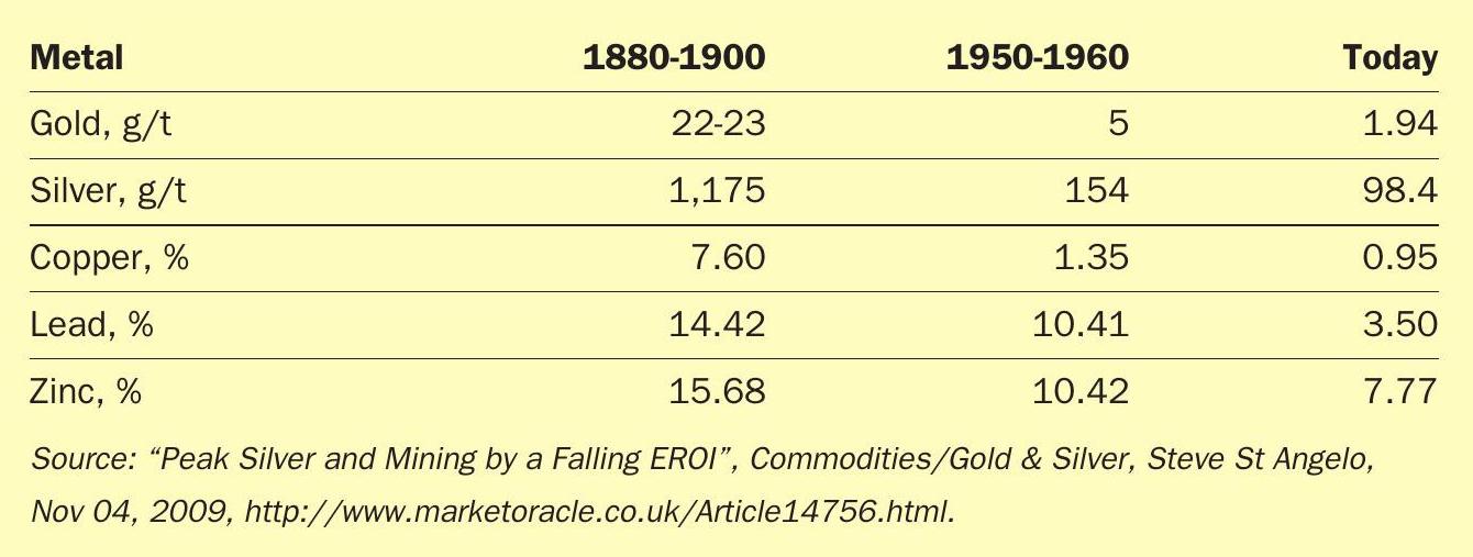
Table 1 illustrates the degradation in ore quality that has taken place since the 1900s.
Decreasing quality leads to increasing amounts of unpleasant impurities, such as arsenic, hydrogen chloride, hydrogen fluoride, mercury, selenium and more. Many of these impurities have a negative and direct effect on the gas cleaning plant, as well as the sulphuric acid plant.
If you increase the amount of impurities to a plant, it is inevitable that it will also directly affect the overall efficiency of the gas cleaning plant, the quality of the acid produced, and the lifetime of the whole plant and process train.
A sulphuric acid plant today must produce high quality acid – this is essential. These higher impurity levels are not only affecting the results and quality of the acid but over time, the equipment as well. Any neglect in facing these issues immediately, or without the proper expertise and know-how, will lead to irreversible damage and a loss of productivity.
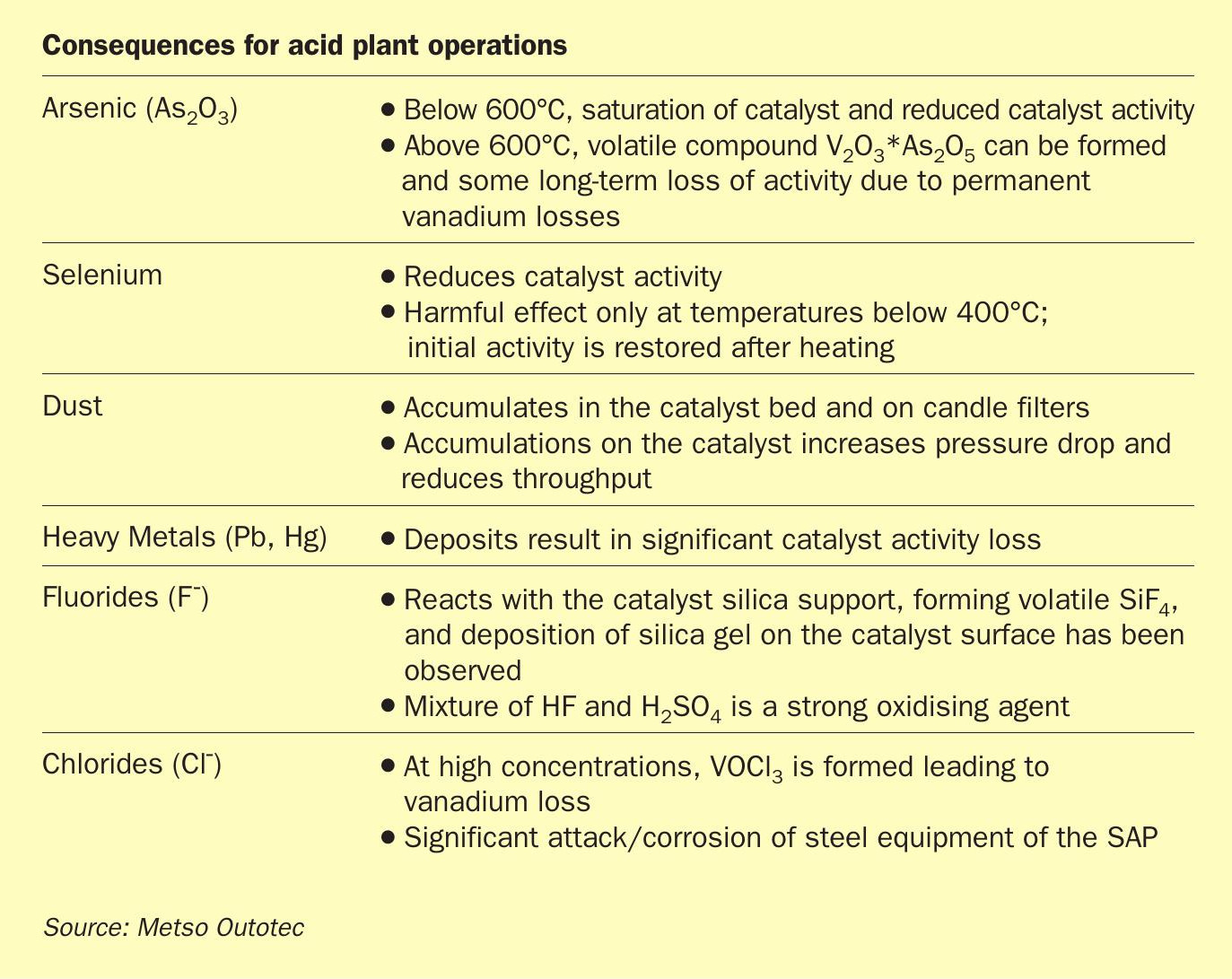
The task of the gas cleaning system is to ensure the reliable operation of the plant, producing sulphuric acid at a specified concentration (e.g. 98.5% concentration) and purity. Acid contaminants including heavy metals such as arsenic, lead, antimony, selenium, and mercury must remain within permitted levels as the cleaned gas is released to the atmosphere. Acid mist removal is also necessary to prevent corrosion within the acid plant itself, while fluoride removal protects the candle filters in the absorbers from damage. The dust removal upstream of the plant must be employed to avoid clogging of tower packing and mist eliminators. Table 2 lists consequences of various deleterious elements on acid plant operation.
Wet gas cleaning system
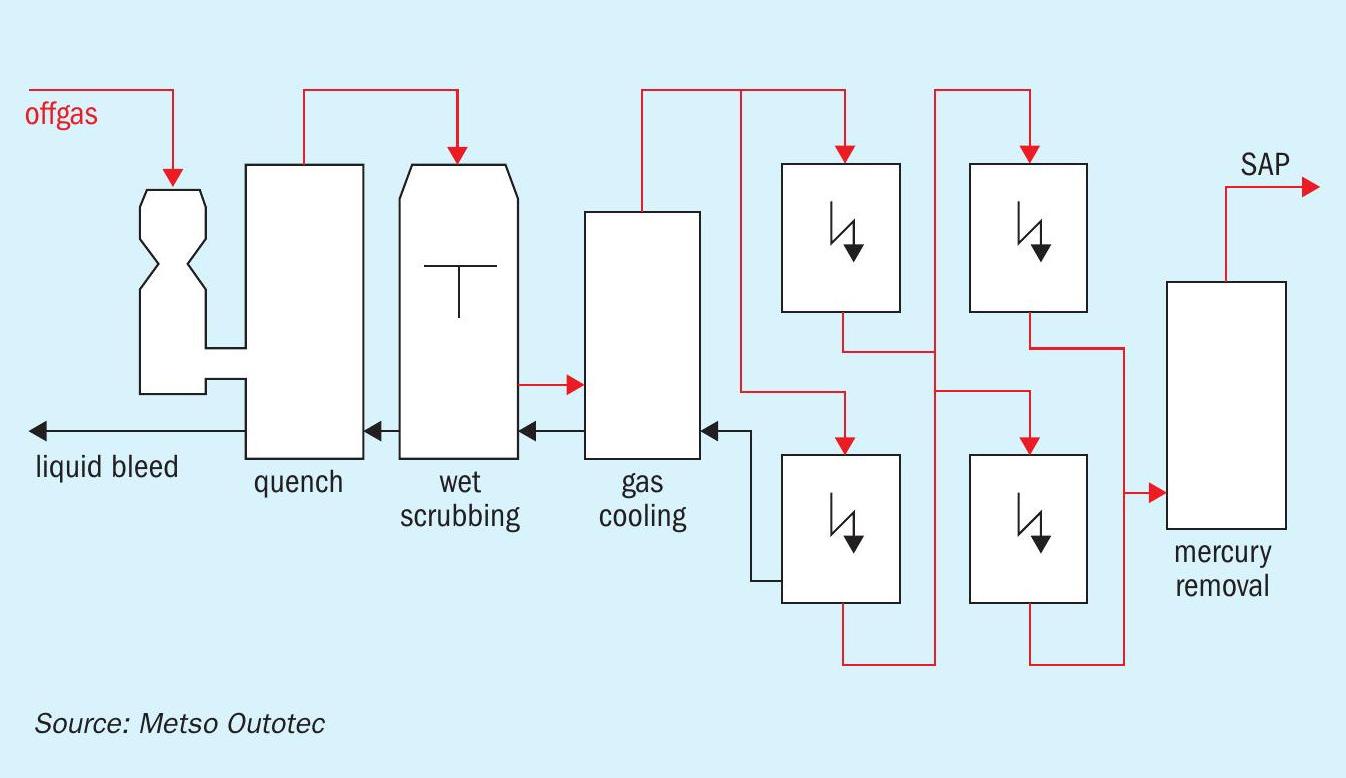
A wet gas cleaning system for a metallurgical sulphuric acid plant consists of a series of unit operations (see Fig. 1).
The unit operations (in order of priority) consists of the following:
- Quench cooler: This operation unit is always installed. Depending on the requirements, the quencher can also be designed for scrubbing or dust elimination. The gas is fully saturated with water at the quencher outlet.
- Scrubber: A scrubber is designed for removing dust from the gas flow. The liquid injected into the scrubber captures the dust particles. Scrubbing efficiency can be improved with an increased energy input into the system. Depending on the dust removal efficiency required, the gas flow characteristics and the dust type, scrubbers may have different designs.
- Gas cooler, water vapour condenser: The amount of water vapour in the gas is reduced to the maximum amount allowed for the sulphuric acid plant water balance. The allowable amount depends on the SO2 content of the gas. When the gas is cooled, the water vapour is condensed.
- Two-stage wet ESPs: Fine dust particles and aerosols are removed from the gas in wet electrostatic precipitators (WESPs).
- Subsequent stages: Elements or compounds which cannot be sufficiently removed from the gas by applying the above unit operations are treated in additional stages. This is true for both gaseous metallic mercury and for halides.
Quench coolers and scrubbers
Many technical solutions have been developed for quenchers and scrubbers. In the quencher, independent of the apparatus design, the gas is cooled when the water evaporates. The heat from the incoming gas with a temperature exceeding 300°C is used for water evaporation, which is then sprayed into the quencher. The sensitive heat of the gas is converted into water vapour (latent heat). The energy (enthalpy) from the incoming gas flow (high temperature and low water vapour content) is the same as the energy (enthalpy) from the outgoing gas flow (low temperature and high water vapour content). This type of cooling can be considered an adiabatic process, i.e. a process operated without an energy exchange with the environment. The gas is usually water saturated at the quencher/scrubber exit. If the temperature is lowered, water vapour will condense.
The quencher normally has a temperature and acid-resistant brick lining. If the downstream installations are sensitive to temperatures exceeding 80°C, the quencher needs to be equipped with two fully independent liquid circuits. Each circuit must have its own pump, pipes and nozzles. This 100% redundancy ensures safe operation in the event of a pump or nozzle failure. In addition, Metso Outotec recommends installing an emergency spray system that will start in case of temperature excess and power failure.
A quencher can also be designed with high removal efficiency for dust. Alternatively, a separate scrubber is installed downstream of the quencher. In cases where substances condensed in the quench cooler are to be removed from the gas, a separate scrubber downstream of the quencher (humidification tower) is recommended. This is the case for arsenic released from copper smelters. Scrubber and quencher design, as well as selection, depend on process requirements such as gas flow rate, dust load, presence of condensable matter in the gas, efficiency required, dust type and particle size distribution, as well as the amount of solids and dissolved matter in the scrubbing liquid.
An important scrubber feature is the careful selection of nozzles. Not only should they be designed to withstand possible temperature excess, but also for the abrasion, which results from particles suspended in the scrubbing liquid. Some scrubbers have special design features for handling fluctuating gas flow rates. This applies for scrubbers with an adjustable throat. An adjustment can be made to the cross-section area of the scrubbing zone, which affects pressure drop and consequently scrubbing efficiency. During operating conditions which require only a reduced scrubbing efficiency, the pressure drop can be decreased, reducing the energy consumption.
The most critical area in a quencher is the transition zone from hot and dry to wet and acidic. Both areas require different types of mortar and bricks. To ensure that there is a clearly defined transition zone, Metso Outotec has developed the “Otovent”, a venturi-type quencher equipped with a ring zone, which allows for a clearly defined wet-dry transition zone (Fig. 2).
Usually, the excess liquid from the wet gas cleaning system is discharged from the quencher circuit as weak acid, which is neutralised in an effluent treatment system. To reduce lime consumption, the SO2 dissolved in the weak acid is stripped out. Stripping is carried out in a stripper usually designed as a packed tower using ambient air. If extensive solid content exists, settlers are used to reduce it in the weak acid circulated in the quench cooler spray circuit.
Gas cooling/water vapour condensing systems
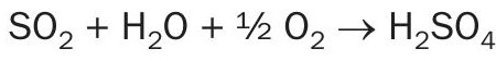
While passing through the quencher/scrubber, the SO2 gas is saturated with water vapour. In the acid plant drying tower, the water vapour is completely removed due to the absorption in the circulated sulphuric acid. When forming sulphuric acid, the following equation applies:
For a single molecule of SO2 , one molecule of water vapour can be in the SO2 gas. Design criteria for the gas cooling stage includes the temperature at the inlet based on the enthalpy of the incoming gas and the gas SO2 content and consequently, water vapour content going to the acid plant, including a certain safety margin. The inlet and outlet pressure are also considered. The system must be designed to take into account the dust and aerosol load, as well as the halides and dissolved matter in the cooling liquid.
Direct cooling of the gas in gas/liquid heat exchangers made of acid-resistant materials such as plastic and lead can bring down the gas temperature very close to the cooling water temperature. However, these coolers, where the gas usually flows through the tubes and the cooling water is guided around the tube bundles, may also be subject to build-up and due to their mechanical design, are very difficult to clean. The most popular gas cooler/condenser model is the packed gas-cooling tower, where liquid cooled in plate heat exchangers is circulated over a packing made of filling bodies. This “indirect” gas cooler/ condenser can be designed to minimise build-up in both the packing and cooling liquid circuit.
Wet electrostatic precipitators
Scrubber efficiency drops significantly for particles smaller than five microns. These small particles are removed in wet electrostatic precipitators (WESPs). Aerosols and dust are eliminated in WESPs from the gas using high tension. The gas flows through a strong electrostatic field, which is made from grounded collection electrodes and negatively charged discharged electrodes where an “electrical corona” is created. The corona releases electrons and electrically charged gas molecules, mainly oxygen. When these ions come into contact with aerosols and particles, they are also charged. Guided by the electrostatic field, the negatively charged particles migrate to the collection electrodes where they are discharged and form a liquid film which flows downward, and drips into the bottom of the casing where it is then drained.
Design parameters for WESPs are the actual gas flow and the efficiency required for dust and aerosol elimination. Operating temperature and operating pressure are also needed for mechanical design. The gas composition and trace gases also need to be determined. Metso Outotec recommends a two-stage system to ensure a consistently reliable operation of this important component of the wet gas cleaning system.
Modern WESPs are designed with round or hexagonal collection tubes made of plastic and arranged in bundles. The discharge electrodes are mounted in the centre of the tubes. Various types and materials are used for WESPs. The casings are manufactured of fibre-reinforced plastic (FRP) or coated steel. Alternatively, the collection electrodes can be made of stainless steel or other corrosion-proof materials.
Fig. 3 shows a wet electrostatic precipitator based on the Metso Outotec design (Editube). The gas flow is usually oriented downwards.
The insulators, which support the discharge electrode system, are an important component of every WESP. Due to the moist and acidic environment inside the WESP, any condensation on the insulators must be prevented. To prevent condensation, two techniques can be implemented: electrical heating and air flushing. Insulator heating is preferable in the case where the SO2 gas must not be diluted. In the event that a WESP is operated under over pressure or fluctuation conditions, air flushing may be a better solution.
Wet ESPs are usually equipped with a flushing system for cleaning of the internals (discharge and collection electrodes). Cleaning usually takes several minutes. During this time, the high tension is switched off. The decision whether the vessel should be bypassed has to be made based on the process design of the installation.
Mercury removal systems
In cases where a significant amount of mercury is present in the gas, a separate mercury removal system is required. Although a large portion of the metallic mercury is removed in the wet gas cleaning system by reactions between the mercury and other ions such as selenium and chlorides, there may still be sufficient gaseous metallic mercury to contaminate the product acid.
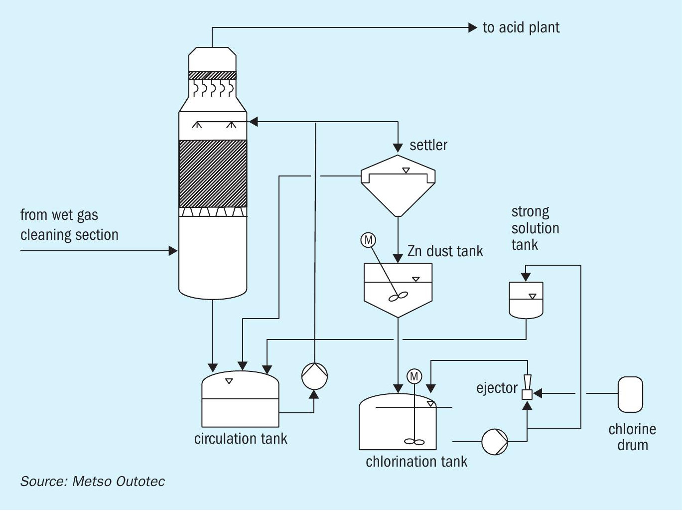
A number of different processes have been developed for mercury elimination. The most popular system used for the elimination of metallic mercury is the Boliden Norzink Process (calomel process) as shown in Fig. 4.
The principle of the calomel process (Boliden-Norzink mercury removal process) is that gaseous metallic mercury present in the SO2 gas reacts with mercury chloride dissolved in a reaction liquid and forms a solid mercury chloride compound, calomel.
Where: Hg is gaseous; HgCl2 is in dissolved complex form; and Hg2 Cl2 (calomel) precipitates as solids.
Calomel is removed from the reaction liquid circuit by liquid/solid separation in a settling tank and stored in a tank arranged beneath the settler. Prior to discharging the excess liquid, the dissolved mercury chloride is also precipitated by adding zinc dust. The reaction liquid containing the dissolved mercury chloride is prepared batch-wise by chlorination of calomel with chlorine gas. This concentrated “strong solution” is then stored in a storage tank and added to the reaction circuit where it is diluted to the concentration required for the operation of the system.
In addition to the standard process, a number of other methods have been developed in a variety of smelters to remove mercury from the SO2 gas or from the produced acid itself. Generally, every process has been designed to achieve sulphuric acid with a mercury content of less than 1 ppm. To achieve mercury contents of less than 0.1 ppm, some copper smelters apply additional mercury removal stages, which have been designed as adsorption processes. These are usually arranged downstream of a calomel process. The mercury-containing SO2 gas passes through an absorber that has several layers of an absorption agent. The mercury reacts with the absorption agent to form an insoluble mercury compound. Selenium is one of the absorption agents that may be used for mercury absorption. Metso Outotec offers a process which utilises a scrubber stage with a selenium filter for achieving mercury contents of less than 0.1 ppm.
Halide removal systems
The major portion of halides has already been removed in the scrubber and packed gas cooling tower by absorption in the circulated liquid. If high liquid temperatures and high concentrations of absorbed matter occur, there may be significant amounts of gaseous halides which can reach the acid plant. This may result in damage to the candle filters, due to fluoride attack.
To reduce the concentration of dissolved fluorides, sodium-silicate can be added to the liquid circulated in the packed gas cooling tower. In the event of very high halide content, a separate fluorine removal tower needs to be installed. Fluorine removal towers are designed as vessels equipped with ceramic filling bodies. The gas flows downwards co-current with liquid circulated in the tower. The filling bodies are eaten up by the fluorides and need to be occasionally replaced. To minimise the acid load and carry-over into the acid plant, the fluorine removal tower is often installed between the two stages of WESPs.
Wet gas cleaning system health check/audit
If problems are observed in a scrubber, it is often useful to touch with the palm of your hand the individual pipes supplying the nozzles with liquid. A human palm is normally very sensitive to temperature. If one of the pipes appears to have a significantly different temperature, the respective nozzle may be lost or blocked. Nozzle loss can be considered more critical than the blockage of a pipe.
The trend of the electrical values is a good indication of WESP operation. If the second stage is in operation with little flash-over (maximum 3 to 5 flash-overs per minute) and the specific electrical current exceeds 0.3 milliampere (mA) per square metre of the collection area, the functioning of the WESP can be considered good. If this is not the case, Metso Outotec recommends a more detailed investigation to determine the reason for the deviation.
For other stages involved in gas cleaning systems, such as mercury removal or fluoride removal, Metso Outotec recommends regular sampling and analysis of the circulated liquid. A good estimate of the overall operation of a wet gas cleaning system with WESP is a lamp section (a 40 W bulb with a sight glass at distance of 5 m). If no clouds are visible, the sulphuric acid mist content is below 25 mg/Nm3 . By installing a simple instrument for measuring the opacity, the mist content and the overall performance of the gas cleaning system can be viewed on the control monitor in the acid plant control room.
Last but not least, Metso Outotec recommends that plants have a regular expert assessment of the process system every 12 to 18 months.