Sulphur 396 Sept-Oct 2021
30 September 2021
The untapped potential of your sulphuric acid plant
SULPHURIC ACID TECHNOLOGY
The untapped potential of your sulphuric acid plant
Tightening regulations and growing global competition are increasing the pressure felt by sulphuric acid plant operators to reduce emissions and improve energy output. Conservation of energy is a continuous focus for operators, and environmental communities have grown more vocal in their desire for greater emissions oversight. In this article, DuPont Clean Technologies examines simple, tried, and true tactics, as well as new products and designs that can be incorporated into existing plants to address operating efficiency and emissions and to help to prolong the life of the plant.
Sulphuric acid plant operators have a number of options to extend the lifetime of assets while reducing emissions and improving energy efficiency. There are regular maintenance activities as well as equipment design improvements that can impact energy conservation and energy generation. Some of these improvements are overt while others may be more hidden, or even counterintuitive. Likewise, some of the suggestions listed should be looked at regularly by operations and maintenance teams, while others require long term planning and implementation at major turnarounds.
Energy efficiency not only means consuming less energy in operations to achieve the same output, but also finding ways to recover or even generate energy. Plants aiming for high energy efficiency should therefore approach energy improvements from multiple angles: conserving energy, improving the efficacy of equipment, in particular rotating machinery, capturing and re-using heat or steam, and transforming that heat into other forms of energy.
Beyond reducing the plant’s environmental footprint, better energy management can therefore both lower operating expenditure and generate value from existing equipment and resources. The following list offers some ideas of how this can be achieved.
Steps to achieve energy and efficiency improvements
Conservation of energy
- Minimise steam losses through steam trap maintenance and steam leak repairs. Losing steam into the condensate line or leaking it into the atmosphere can be a large hidden loss of energy.
- Maintain duct integrity to avoid air ingress upstream of the compressor, as this can increase the volume of gas that the compressor must move, which in turn uses more energy.
- Keep sulphur feeds clean and maintain inlet air filters to avoid dust and deposits in the converter and boilers. Dust and salt deposits increase pressure drop.
- Maintain insulation integrity on all vessels, ducts, and piping to minimise heat loss to the atmosphere. Good insulation will also keep the plant hot during short outages and reduce heat-up time and fuel needed for heat up.
- Consider new heat exchanger designs for lower pressure drop and greater thermal efficiency.
- Consider retrofitting existing towers with lower pressure drop internals using new packing and a different mist eliminator element style or count.
- Consider new catalyst designs to reduce pressure drop.
- Review continuously operated air preheaters for maximum efficiency and lowest levels of NOx emissions. Watch for fouling or burner issues that can reduce efficiency.
Improving rotating equipment efficiency
- Consider changing fixed speed motors to variable frequency drives (VFD). This allows removal of flow or level control valves downstream, reducing pressure drop. Main compressors are good targets to review. With a VFD controlling output, inlet guide vanes or the inlet dampers can be eliminated, again reducing pressure drop. VFDs have become less expensive and should also be considered for larger pumps.
- Operate pumps at the optimal points on the pump curves. Update flow system pressure drop calculations to right-size pump impellers and eliminate unnecessary throttling.
- Consider high efficiency (85%) motors for larger installations.
- Consider soft starts on large motors to minimise voltage drop.
- Evaluate compressor and turbine drive to improve efficiency. As rotating equipment wears, efficiencies can decrease. This may require equipment supplier support to make sure the equipment operates at peak performance.
Generating/recovering more heat
- Increase deaerator pressure to allow for greater treated water preheat to transfer more of this heat to the high-pressure steam system.
- For plants with existing power islands, maximise power production from steam by maximising condenser vacuum, keeping the condenser tubes clean, and operating with a full contingency of tubes (minimise number of plugged tubes).
- Maximise the steam superheat and pressure to the turbine. Higher pressure and higher temperature provide more energy recovery. Focus on keeping the plant operating at design conditions and maintaining clean heat exchange equipment.
- Install low temperature economisers upstream of acid towers to capture more heat.
- Recover low level heat from the strong acid system for treated water preheat. l Increase the sulphur dioxide (SO2 ) gas strength to 12% for optimum steam production. Modernising the catalyst selection and placement is key to operating at higher gas strengths.
- For spent acid regeneration plants, maximise air preheat to SAR furnaces.
- For spent acid regeneration plants, consider oxygen enrichment to limit fuel gas usage.
SO2 removal technologies for lower stack emissions
Improving energy efficiency is, however, only one aspect of reducing the ecological impact of sulphuric acid plants. For many years now, emissions control has also had a large part to play, with governmental regulation and public opinion imposing every tighter restrictions on emission limits around the world. While global emissions standards are less than 100 ppm SO2 , local regulatory requirement in many areas are much lower at 20 ppm. Satisfying local communities and pressure groups has become a key element of sulphuric acid plants’ right to operate. The conundrum has been how to cut emissions reliably, lastingly and in a way that does not impact but aid operations productivity.
The simplest way to reduce emissions is to optimise catalyst selection in terms of loading, and to choose the right type of catalyst for each catalyst bed, as shown in the two examples below:
Example 1
A metallurgical customer with a conventional double absorption plant with MECS® HRS™ had a design feed gas composition of 14.0% SO2 and 14.0% O2 . The converter contained conventional catalyst in bed nos. 2 and 3 with a 50% cap of caesium-promoted Cs-120 in pass no. 1 and Cs-110 ring catalyst in bed no. 4. The caesium-promoted catalyst in pass no. 1 was used to control the highly exothermic reaction in the first pass. Operating the inlet temperature to the first pass at 390°C, the outlet temperature could be controlled to 635°C. The overall result was a stack emission of less than 75 ppm SO2 .
Example 2
A sulphur burning customer needed to reduce stack emissions to 100 ppm, adjusted to an 8% O2 basis. The plant was a 3X2 interpass plant with air dilution cooling between passes 4 and 5. The feed gas composition was 11.5% SO2 with 9.45% O2 . The converter contained conventional LP-120/LP-110 catalyst in pass nos. 1, 2, 3 and 4, with caesium-promoted Cs-110 ring catalyst added to bed no. 5. The use of the caesium promoted catalyst allowed pass no. 5 to operate with an inlet temperature of 390°C. The result was a stack emission level of less than 100 ppm.

Additionally, several other upkeep items and activities should be considered:
- Consider upgrades to absorbing tower mist eliminators to reduce mist and pressure drop. Install MECS® concentric elements to increase collection area and reduce gas side pressure drop.
- Keep mist eliminators well maintained and seal cups full. Consider Brink® AutoDrain™ mist eliminator designs to avoid seal cup problems, especially when replacing an absorbing tower.
- Maintain design temperature on both gas and acid streams into the absorbing towers.
- Consider electric preheat for catalyst beds to provide heating for plants without a fired heater to reduce greenhouse gas emissions.
Ultra- low stack emissions
The two basic options to reach ultra-low stack emissions levels are:
- wet scrubbing with a base or hydrogen peroxide;
- regenerative scrubbing.
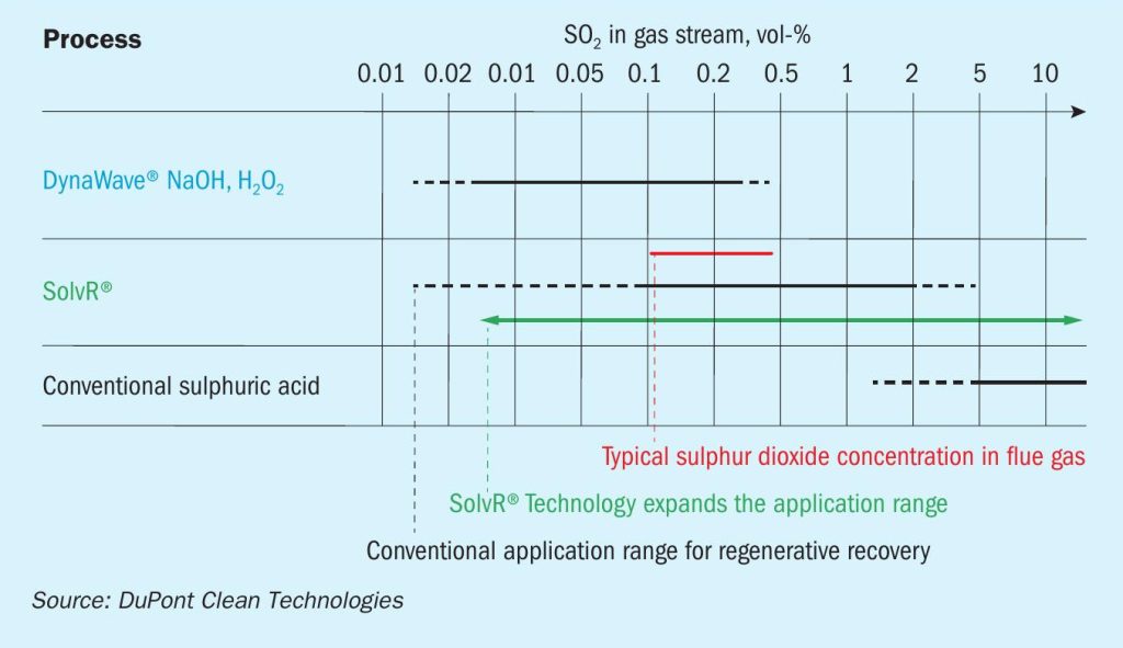
The economic viability of each approach depends on many variables. Two of the more important factors to consider are the gas flow rate and the concentration of sulphur dioxide in the inlet gas. Fig. 1 shows the typical application range of different MECS® technologies based on the inlet gas concentration. In the case of a low gas flow and/or a low SO2 concentration, typically the most attractive approach is to use a wet scrubber with either sodium hydroxide or hydrogen peroxide since scrubbers represent lower capital costs than regenerative scrubbing. However, as the gas flow and/or SO2 concentration increases, the raw material, handling, and disposal costs dominate, and the operating costs overwhelm the savings on capital. In this case, the use of a regenerative technology such as MECS® SolvR® becomes very economically attractive.
The economics of wet scrubbing
Caustic wet scrubbing, such as MECS® DynaWave® scrubbing, typically represents the lowest capital investment approach and can be applied when the gas flow and/or the concentration of sulphur dioxide in the inlet gas to be treated is relatively low. The sulphur dioxide is converted to sodium sulphite which is then oxidised with air to sodium sulphate. The sodium sulphate generated will then be sent to the wastewater treatment facility. As the flow and concentration of sulphur dioxide in the feed gas increases, the cost of raw materials and waste disposal costs increase quickly and the small savings in capital are overshadowed by the operating costs. For a flow of about 100,000 SCFM and an inlet concentration of 1,800 ppm SO2 in the inlet gas, the savings in capital will be paid back in about 19 months. When the concentration of SO2 is higher than 1.8 vol-% then the incremental capital can be paid back in only two months through the savings in operating costs.
Alternatively, hydrogen peroxide could be used to react the sulphur dioxide to form sulphuric acid. A slight excess of peroxide is used to ensure a complete reaction and the excess is decomposed in another vessel. In this case, the sulphur dioxide is recovered as product which is not the case for caustic scrubbing. Unfortunately, the cost of hydrogen peroxide is higher than the value of the sulphuric acid produced, and as the concentration of SO2 increases, the operating costs increase proportionately.
In a limited number of applications, the sulphur dioxide could be reacted with caustic to both reduce emissions and produce an aqueous solution of sodium bisulphite. This configuration would require a larger capital investment to produce a sufficiently high-concentrate solution of sodium bisulphite that could be sold commercially. Special attention needs to be paid to avoid generating larger concentrations of sodium sulphate that may render the product not saleable.
This process will require a tail gas scrubber to ensure that sodium bisulphite is produced. In addition, storage tanks for caustic and the product sodium bisulphite need to be installed. Furthermore, to market the co-product, clients need to be relatively close to avoid excessive shipping costs. As there is a limited market for this co-product, this approach is not commonly utilised.
Regenerative SO2 scrubbing
The MECS® regenerative SO2 technology, SolvR® , absorbs sulphur dioxide in the inlet gas at concentrations ranging from 300 ppm to 50 mol-%. It has low pressure drop that makes it amenable for installation in existing manufacturing facilities without requiring significant changes to existing equipment. The main input utility is steam that is used during the stripping step of the process.
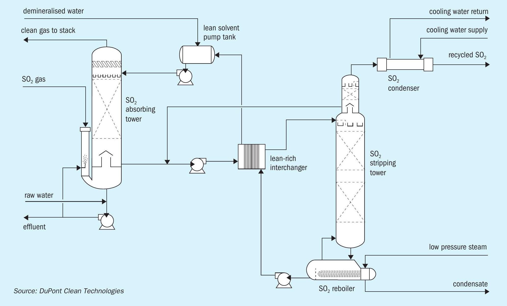
MECS® SolvR® process description
The MECS® SolvR® absorber is a packed tower which removes the sulphur dioxide from the hydrated gas with lean solvent. The clean exhaust gas (containing less than 20 ppm SO2 ) is sent to the stack. Emission levels can easily be controlled or adjusted by adding more lean solvent to the absorber and by adding steam during stripping (Fig. 2).
The rich solvent, which now contains sulphur dioxide, is sent to the lean-rich heat exchanger where most of the sensible heat is recovered by exchanging it with the hot lean solvent. The rich solvent having been taken to a temperature of about 200°F (94°C) is then fed it to the stripping column. The absorbing solvent essentially has no vapour pressure. Consequently, above the feed tray there is only water and sulphur dioxide. The overhead gas containing about 95 mol-% sulphur dioxide and 5 vol-% water is then sent to the drying tower and eventually converted to sulphuric acid.
Since most gases contain oxygen in the feed gas (11.5 mol-% in this system), some of the sulphur dioxide reacts, forming SO3 , which in this system is in the form of sodium sulphate. About 0.5% of the sulphur dioxide is oxidised and the sulphate formed is removed by the anion exchanger.
The MECS® SolvR® system offers several advantages when compared to other regenerative scrubbing systems including:
l a solvent with several unique properties, i.e., environmentally friendly, minimal make-up requirements and low cost; l a steam stripping arrangement that utilises novel techniques developed to optimise energy efficiency;
l an effluent volume that is minimal and consists primarily of sodium sulphates (no acids) which are easily managed from an environmental perspective and often can be discharged directly to the plant sewer.
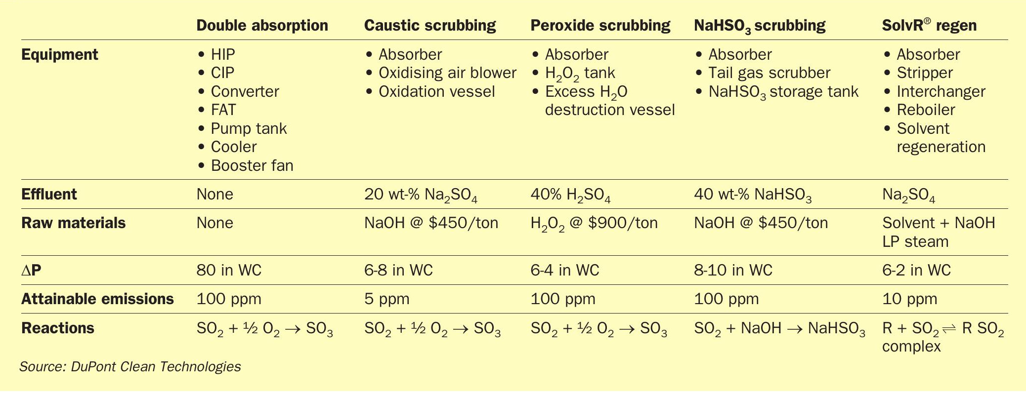
Comparison of SO2 abatement technologies
Table 1 illustrates different options for modifying an existing single absorption plant or when considering a new plant. These options are double absorption, scrubbing, and regenerative technology. Traditional wet scrubbing generates a large amount of effluent that needs to be treated and disposed of. The disposal costs as well as the raw material costs increase with the rising flow rate of SO2 in the gas stream. Regenerative technology has low effluent and low operating costs; however, the capital cost is higher than for traditional wet scrubbing technologies.
Green energy – recovering more heat
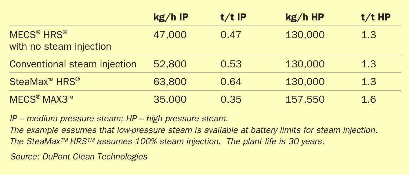
Plant owners, neighbouring communities, and environmental groups all like the green energy that is co-produced in the manufacture of sulphuric acid. The MECS® HRS™ heat recovery technology for sulphuric acid plants allows them to produce carbon-free energy and has close to 40 years of accumulated operation, with over 100 units installed worldwide. As demand across the globe grows for investment in green, carbonless energy, the MECS® HRS™ technology continues to improve and expand. Refer to Table 2 for a summary of the MECS® HRS™ steam generation technologies.
In the sulphuric acid process, energy is released through combustion and exothermic chemical reactions, and is recovered as high-pressure steam. Low level energy, like the heat from SO3 hydration, is normally not economical to recover and is therefore rejected to the cooling tower. With MECS® HRS™ technology, sulphuric acid plants can significantly increase their thermal efficiency by upgrading and recovering this low-level energy as medium pressure steam (up to 150 psig (10 barg)). Steam generation typically ranges from 0.4 to 0.6 tons of steam per ton of acid produced, depending on the SO2 concentration and water balance considerations. This steam can then be used to produce electricity in the order of 3 MW per 1,000 t/d acid.
In the MECS® HRS™ technology, heat is removed in the HRS™ boiler, and water and steam are added in the process to control the acid concentration. Energy contained in the product acid may be recovered by heating water in the HRS™ heater and preheater. This heating results in additional steam generation as well as reduced cooling water use in the plant.
MECS® SteaMax™ HRS™ exports more medium pressure steam than a typical MECS® HRS™ . It raises the ratio of dilution steam to dilution water and increases generation of medium-pressure steam. Low-pressure steam is added to the system for acid dilution. The energy in this low-pressure steam is then recovered as medium pressure steam in the HRS™ boiler. This upgraded steam has more value and gives plants greater flexibility in steam use and customisation to site-specific energy requirements and local conditions.
The MECS® MAX3™ technology is the next stage in sulphuric acid plant energy upgrades, allowing for up to 20% more high-pressure steam to be exported from the sulphuric acid plant. By employing a heat exchange networking system, MAX3™ technology shifts the MECS® HRS™ energy that would normally be used to generate medium-pressure steam in the HRS™ boiler to a high-pressure steam system that allows for greater production of high value, high-pressure steam.
MECS® MAX3™ technology can also integrate with the SolvR® technology, resulting in an ultra-low emission, high efficiency sulphuric acid plant design, especially useful for grass roots installations. Utilising MECS® MAX3™ and SolvR® technologies will allow acid plants to produce high-quality acid at nameplate capacity or above while maintaining ultra-low greenhouse gas emissions. Additionally, the resulting low effluent rates will minimise water losses. This plant arrangement maximises carbonless, green energy production that can either be turned into power for sale or used internally.
But energy efficiency and air emission reduction are only two on a long list of objectives for sulphuric acid plant operators. In a high acid environment, the longevity and reliability of equipment are also important considerations and cost factors. MECS® HRS® and MAX3® are designed with durability and low maintenance in mind. An example is a sixteen-year-old plant with MECS® HRS™ technology, operating in China that has an on-stream time greater than 98%. Overall, downtime including turnaround time at this plant accounts for less than 2.5 % of the cost of equipment replacement.
The selection of the right equipment with demonstrated reliability and correct maintenance are key to a long plant life. State-of-the-art equipment such as Brink® AutoDrain™ mist eliminators and new catalyst can reduce maintenance and extend plant life. Adding new bolt-on-systems can increase maintenance needs but will bring other benefits as discussed above.
Conclusion
Reducing emissions, improving energy efficiency while unlocking value from existing assets and prolonging the life of a sulphuric acid plant are no simple matter. There is no single solution that will address all these challenges. They rather need to be viewed holistically so that any changes made to existing assets are aligned with each other to achieve maximum benefit. As outlined, it is possible to design or upgrade sulphuric acid plants to achieve a balance of energy efficiency, emissions reduction and plant longevity through technology solutions such as MECS® MAX3® and regenerative SolvR® that are not only economically viable but maximise carbonless energy generation at the same time as achieving ultra-low carbon emissions.