Nitrogen+Syngas 374 Nov-Dec 2021

30 November 2021
Green technology progress for a more sustainable future
GREEN TECHNOLOGIES
Green technology progress for a more sustainable future
Reducing carbon footprint in the synthesis of chemicals is a new challenge, a necessary requirement in the pursuit of sustainable products designed to minimise environmental impacts during their whole lifecycle. So-called “green” technologies for ammonia, methanol and hydrogen are being developed to meet these challenges. Casale, Linde, thyssenkrupp Industrial Solutions, Toyo Engineering Corporation, Haldor Topsoe and Stamicarbon report on some of their latest developments.
CASALE
Casale green technologies
Green ammonia, hydrogen and methanol will become increasingly important as the world works towards the goal of sustainable power production which minimises environmental impacts and carbon footprint.
For several years, Casale has been active in the development and optimisation of new green technologies for the production of ammonia and methanol, two of the most energy intensive chemical products, responsible for the emission of large quantities of CO2 .
Casale can design and deliver the full scope for green ammonia and methanol plants including the converter, synthesis loop and optimal balance of the plant configuration.
Casale currently leads several research projects on green technologies and is engaged in a large number of proposals with capacities in the range 3-5,000 t/d.
Casale green ammonia
Today Casale offers a wide range of modern technologies focused but not limited to ammonia, and embracing the full scope of green ammonia production.
Casale is also an engineering supplier of components for other sections of the green ammonia plant such as hydrogen storage, ammonia storage, as well as solutions for green plant digitalisation and optimisation, and solutions for green ammonia use, ammonia cracking to hydrogen or conversion into nitrogen fertilizer.
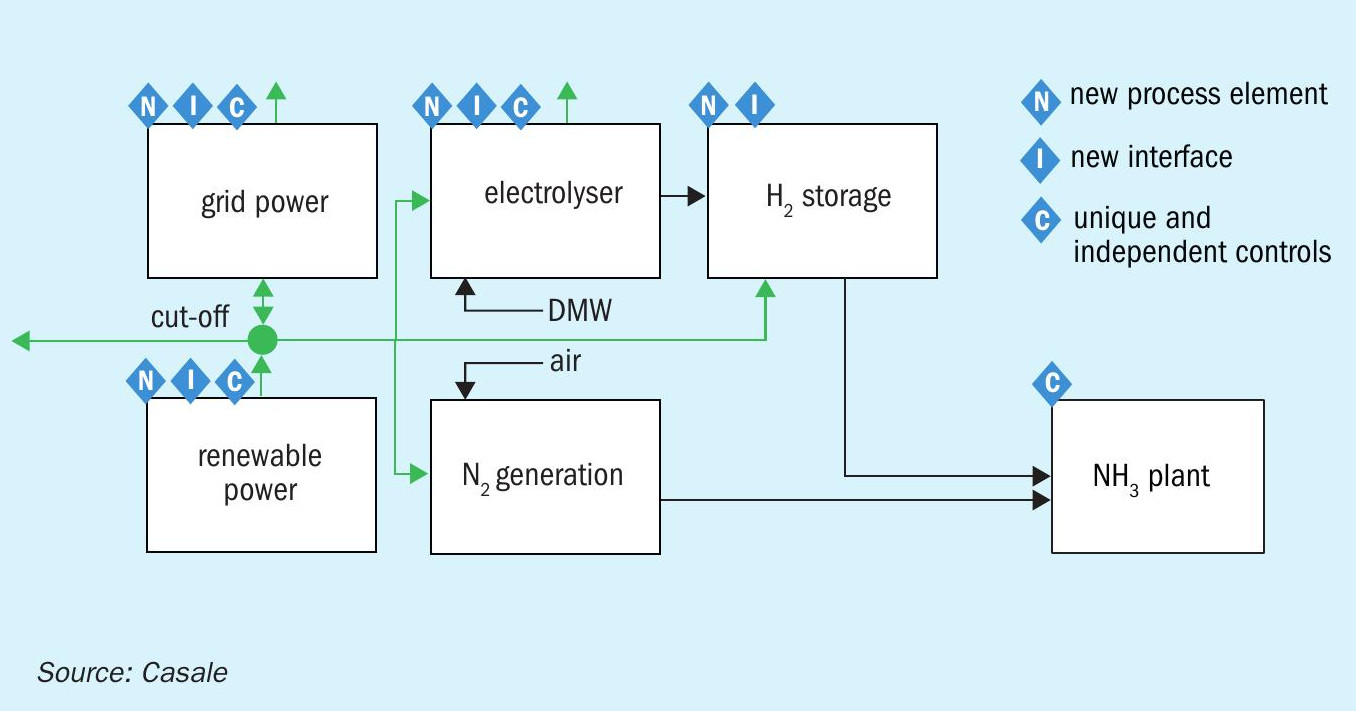
A major difference of a green ammonia plant compared to a conventional (grey) ammonia plant is that the energy comes from a renewable source, which often fluctuates, also resulting in fluctuations of hydrogen and nitrogen. The intermittency of the power supply requires the ammonia plant to be more flexible, otherwise the process will suffer from operational interruptions, and impact on the production cost by requiring more capex to stabilise the fluctuations. To cope with such challenges the green ammonia plant comes with new elements (e.g. electrolyser, H2 storage), new interfaces between those elements, and a unique control system compared with a conventional process (Fig. 1).
Profile fluctuations vary according to location and power source. It is therefore important to work from real power input profiles for green ammonia.
Casale has mastered the understanding of dynamics in green ammonia production under variable power input to develop a uniquely flexible green ammonia solution, which delivers a significant cost advantage over conventional non-flexible green ammonia synthesis by requiring less hydrogen storage capacity.
Casale has developed new dynamic tools specifically for this purpose:
- gNH3 Optimiser: this tool provides optimal component pre-sizing, energy utilisation, and optimised control of the whole process to the target levelised cost of ammonia, based on yearly power profiles and leveraging flexible Casale design features of 10-110% load flexibility with >100% per hour load change.
- gNH3 Dynamic Model: this tool is a dynamic process model of the plant which can simulate the process using scenarios from real fluctuations of the power profile. It allows fine tuning of the system, troubleshooting and scheduling.
Casale’s flexible patent pending green ammonia process combines control and process technology to convert real fluctuating power profiles into green ammonia which is validated by these tools.
Loop flexibility is achieved with a patented solution for the control of the ammonia synthesis converter and the use of Amomax™ -Casale synthesis catalyst.
With a conventional nonflexible or “rigid” loop, fluctuations of the power input (feedstock flow) are absorbed by a huge and expensive hydrogen storage unit that guarantees constant operation of the loop at 70-110% of the load.
With the “flexible” loop offered by Casale the fluctuations are absorbed by a smaller hydrogen storage unit and the loop is operated at 10-110% load. The size of the hydrogen storage unit and the loop are cost optimised and tailored to the input power profile.
Through the analysis and optimisation of real, project-specific, power input profiles, and with the aid of Casale dynamic tools, a tailored flexible green ammonia plant can be designed, resulting in the lowest levelised cost of green ammonia, embracing the full scope, and operating based on real profiles.
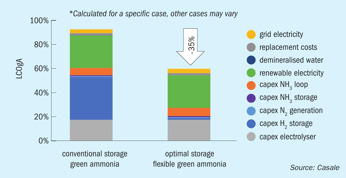
Fig. 2 shows the benefits of Casale flexible green ammonia compared to non-flexible green ammonia production calculated for a specific PV solar energy case in the US.
In this case study, a 35% reduction of the levelised cost of ammonia is achieved with the Casale flexible green ammonia process compared to a conventional one.
A stream of green hydrogen from electrolysis or biomass gasification can also be integrated into a standard ammonia plant to achieve partial decarbonisation of the production. If the hydrogen source is not steady (e.g., H2 from electrolysis using PV electricity) Casale dynamic tools can be used to cost optimise the energy utilisation and plant modifications to provide a stable plant operation throughout.
Casale green methanol
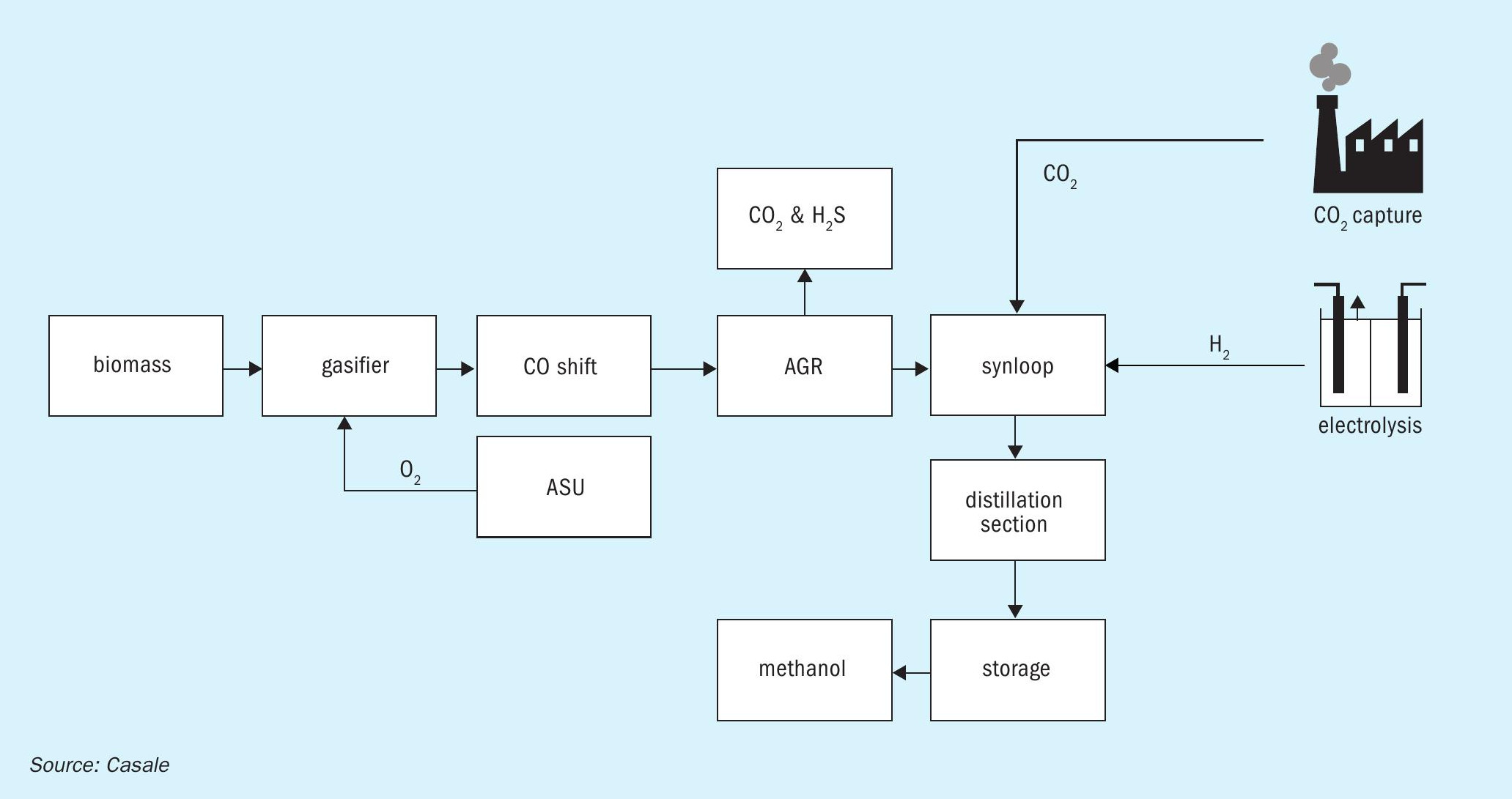
Green methanol (or bio-methanol) may be produced via biological pathways (anaerobic digestion), thermo-chemical pathways (gasification) or electrofuel pathways (power to gas).
The biomass gasification route leads to a plant which is similar to a coal gasification plant, for which Casale has almost 20 references in China.
For these types of plant Casale can provide the CO-shift section, synthesis loop, distillation, and storage.
Green methanol from hydrogen from electrolysis and CO2 recovered from flue gases is also feasible. In this case the reactivity of the feed gas is much less than gasification route, despite the low inert content.
A combination of the two routes is also possible.
Fig. 3 shows a block diagram for a green methanol process.
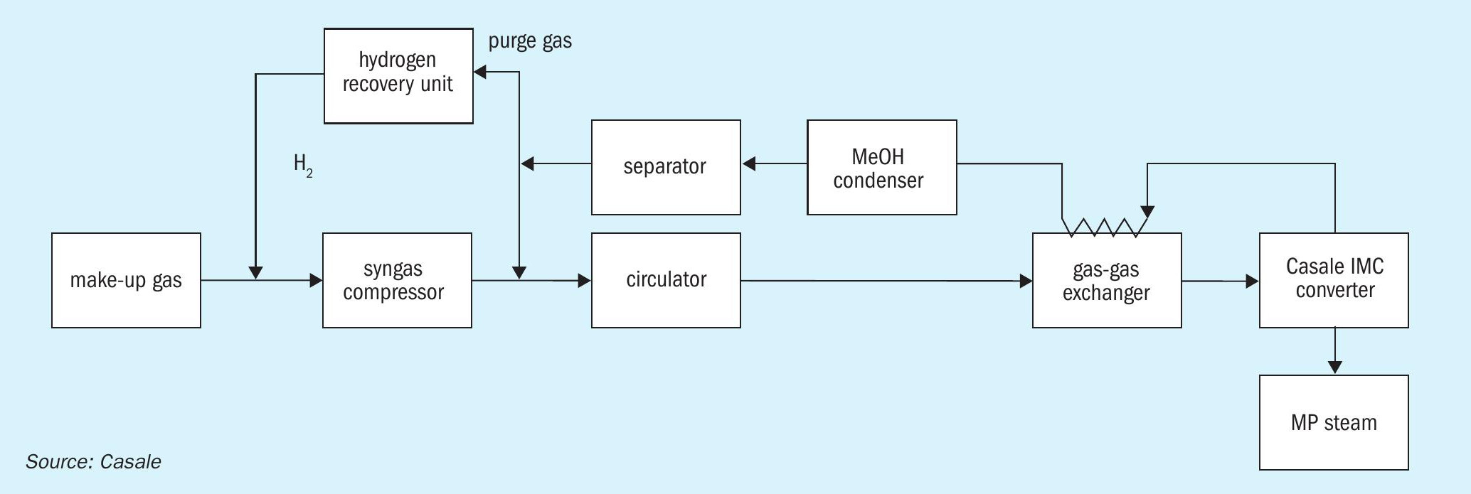
Overall, the synthesis loop can be very simple. It consists of the synthesis converter, a gas-gas exchanger preheating the reacting gas entering the converter, a condenser to cool down the gas to the methanol condensation temperature, a separator to separate the liquid raw methanol from the unreacted gas, a purge recovery unit to recover hydrogen from the purge gas so as to correct the stoichiometric number for biomass gasification plants, and the syngas and circulating compressor.
There are six main items overall, to which a guard bed may be added on the make-up gas for protection from possible spikes in poisons content.
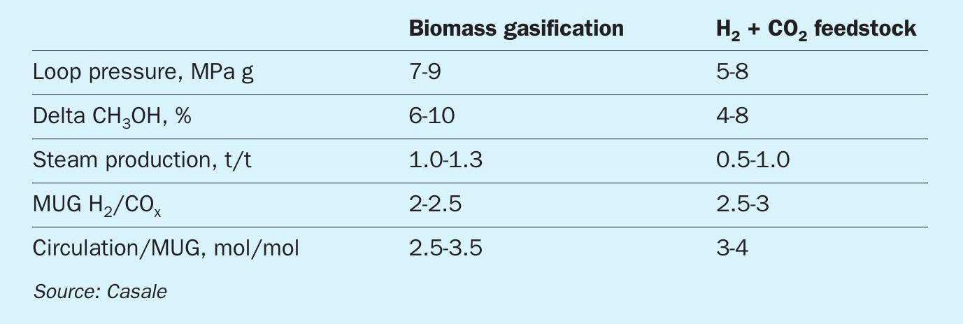
Fig. 4 shows a block diagram for the methanol synthesis loop and Table 1 provides the key performance indicators for green methanol.
LINDE
Linde green ammonia production
Numerous legislative decisions regarding the reduction of greenhouse gas emissions require a transition from the current fossil fuel based electrical energy generation towards an environmentally friendly renewable energy production. The location- and time-dependent availability of renewable energy requires energy storage and transport. Green ammonia meets these requirements. The Linde Ammonia Concept (LAC™) can be a key component in todays and future sustainable energy production and storage.
The United Nations (UN) agreed to limit global warming below 1.5°C at the 2015 UN Climate Conference and the European Union (EU) committed to climate neutrality by 2050. In light of these decisions, green ammonia is a promising opportunity to transport energy at reasonable costs from remote global regions with large green power availability to areas with high energy demand. Furthermore, a fall back on an already existing infrastructure for transportation, storage and distribution is possible.
Up to now traditional ammonia production technology has been mainly based on the processing of fossil feedstocks, whereby the feedstock is converted by means of a thermochemical conversion process to a hydrogen-rich synthesis gas. The carbon from the feedstock is released as carbon dioxide to the atmosphere or to some extent temporarily bound if it is used downsteam for the production of urea fertilizer.
Since all required technologies for small scale, as well as large scale, are commercially available, the possibility to use green ammonia as a zero-carbon fuel and energy carrier is a very attractive approach. Although ammonia production is a proven technology, the process setup for green ammonia production needs to be adapted and optimised to meet the challenge of zero-carbon energy storage applications. The major process modification affects the syngas generation. Green ammonia needs green hydrogen. The hydrogen has to be generated in electrolyser units which are powered by renewable energy. The optimisation challenge is to tune the process in such a way, that it can handle fluctuations in renewable power availability and still be efficient at a minimum capital expense.
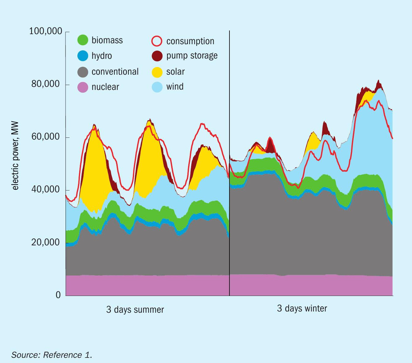
Fig. 1 represents data depicting a large discrepancy between the electrical power consumed versus the electrical power produced by renewable energy sources. Currently the difference is compensated by adapting the power production from fossil fuels.
In light of the committed greenhouse gas reduction goals the conventional CO2 emitting power generation plants (e.g., coal-fired power plants) need to be replaced by renewable energy plants. A simple one-to-one replacement of fossil fuel derived power production with wind and solar power is not a viable option due to dependency of power production based on weather conditions. Obviously, it is therefore necessary to decouple the power consumption from the non-deterministic intermittent wind and solar energy availability. Thus, green ammonia or green hydrogen as energy carriers can help to resolve the dilemma between renewable power production and power demand, which are usually not completely congruent with respect to timing and the location of production and consumption.
Ammonia as an intercontinental energy carrier
Fig. 2 shows a potential example for an ammonia-based intercontinental energy carrier route utilising renewable power to produce hydrogen and ammonia to distribute to consumers.
Electric energy generated by means of renewable power (e.g. solar, wind, etc.) is used to produce high purity hydrogen via water electrolysers as supplied by ITM Linde Electrolysis. High purity nitrogen is generated from air separation units, e.g. FLEXASU® as supplied by Linde. Subsequently pure hydrogen and nitrogen are fed in a molar ratio of H2 /N2 = 3:1 to the inert-free Linde Ammonia Concept (LAC™) which utilises the Haber Bosch process to generate ammonia.
Ammonia is used widely within the chemical industry and the fertilizer industry is a major consumer of ammonia. The fertilizer industry could process green ammonia and thereby reduce greenhouse gas emissions. In the future, ammonia could be decomposed back to hydrogen in large-scale ammonia crackers, whereby the hydrogen could be used for multiple applications, as in steel refining, the chemical industry, or as fuel for the mobility sector.
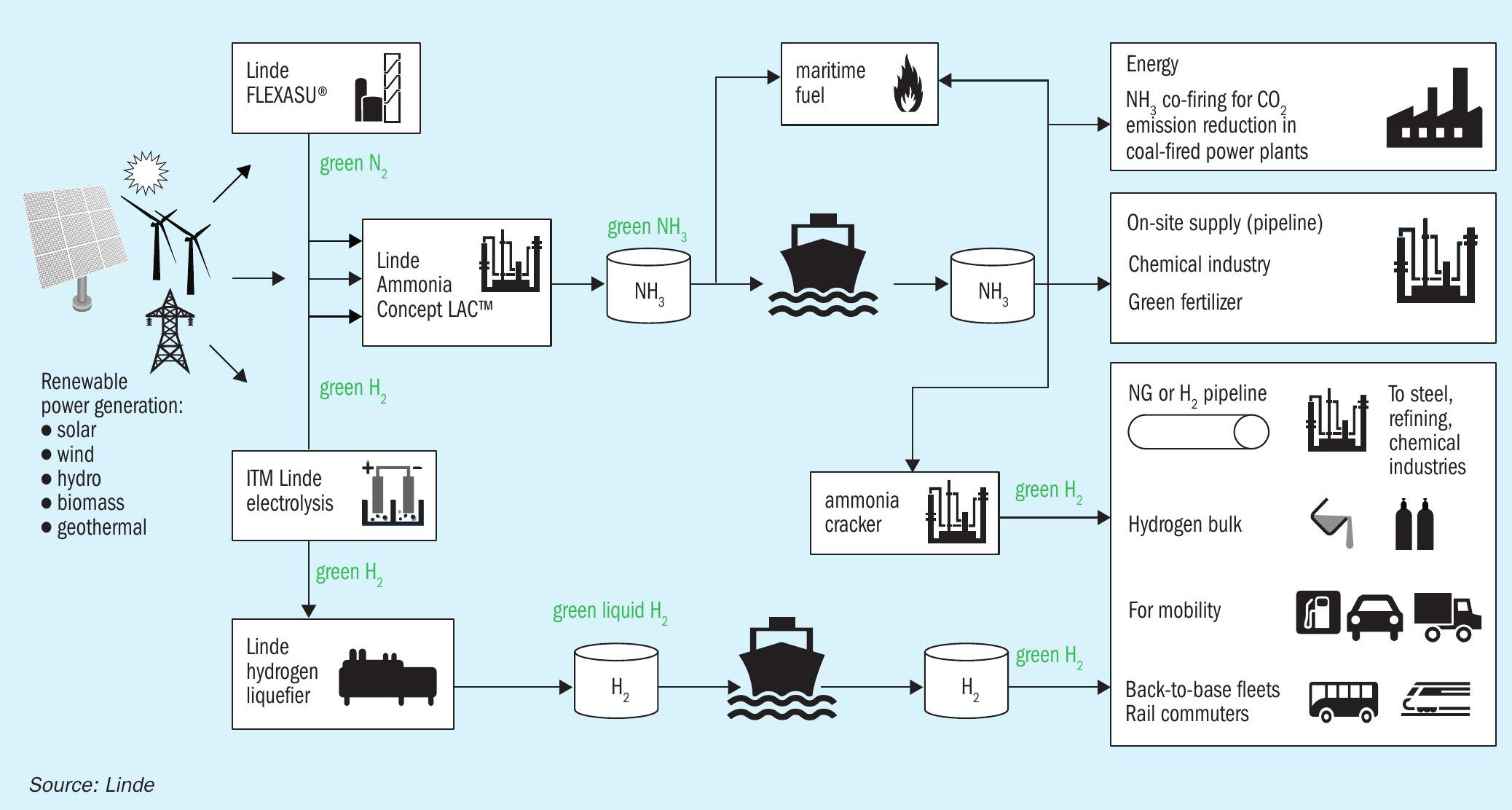
A potential additional future ammonia consumer is the shipping industry where ammonia could be utilised as a zero carbon containing maritime fuel to reduce/ eliminate greenhouse gas, as well as sulphur emissions. In Japan, ammonia is already used as fuel for co-firing in existing coal fired power plants to reduce greenhouse gas emissions2 .
Hydrogen generation
The green ammonia production process differs from the hydrocarbon-based route mainly due to its hydrogen production step. The electrochemical splitting of water can be accomplished by different electrolysis technologies. Today’s most advanced commercially available systems from a viewpoint of technical readiness are based on alkaline electrolysis (AEL) and proton exchange membranes (PEM). Both technologies are likely to experience significant improvements with respect to capital costs and operational expenses within the next years4 . Market competition will accelerate innovation and push costs further down. Of the two technologies, PEM is likely to be the one with the greatest potential for improvements.
The main feedstock, besides electricity, is water. It needs to be completely demineralised, since the electrolyser cells are very sensitive to any contaminants. The demineralised water is continuously fed to the electrolyser water cycle as make-up for the chemical consumption. The water cycle fulfils several duties. First, it routes the water educts to the electrolysis stacks and transports the evolved product gases from the cells. Subsequently, the product gases are separated in dedicated knockout drums for hydrogen and oxygen. Furthermore, the water flow ensures the heat removal for stack temperature control. A precise temperature control of the water cycle is necessary to keep the stacks at optimum performance. The generated raw hydrogen requires little purification effort to achieve the final product purity. Oxygen impurities are removed within a catalytic de-oxo system and excess moisture is eliminated by a dryer station.
Today’s technology suppliers offer complete systems with proven design and successful track records. For instance, ITM Linde Electrolysis (ILE) electrolysis packages are characterised by the following features:
- differential pressure operation for inherent safety and raw hydrogen purity of greater than 99.99 %;
- ITM’s technology with carry-over of proven design features ranging from H2 refuelling station product offerings to containerised solutions for resilient industries;
- GigaStack designed and constructed for high current density operation of up to 4 A/cm²;
- GigaStack designed with vertical erection on top to achieve a compact plot space;
- scaling from 220 kW to 5,000 kW over the last ten years.
The superior dynamic behaviour and enhanced turndown ratios of the PEM technology are capabilities that are of fundamental importance for good overall efficiency in the power to ammonia conversion route. Fast response times minimise production losses. Rapid load changes, even within seconds, additionally allow for grid stabilisation services. The design challenge of electrolysis units is driven by a trade-off between efficiency, degradation rate and capital cost, since it is not easy to achieve best results in all three disciplines at the same time. A techno-economic analysis considering all project specific constraints (e.g., power profile, cost, capacity, economic parameters, etc.) helps to choose the optimal PEM electrolyser system set-up.
Nitrogen generation
In conventional ammonia production from hydrocarbon (HC) feedstocks the air separation unit (ASU) constantly supplies nitrogen to the process without major dynamic load changes.
Green ammonia production requires a flexible, power supply-oriented operation of the ASU. The energy-optimised operation of the ASU represents the primary objective because long-term scheduling can be adapted to the expected availability of renewable energy sources (e.g., weather forecast) and fluctuations in energy availability can be balanced at short notice by immediately regulating the operation mode of the plant. For the long-term operational planning of the ASU, a so-called demand side management (DSM) tool is applied, whereby the operation of the ASU is adapted according to the availability of renewable energy and the energy price. For this new operational requirement, the FLEXASU® has been developed by Linde.
In this regard, the plant and equipment design must consider cyclic loading due to more frequent start/stop operations required by the advanced process control system (APCS). Additional flexibility can be provided by a storage tank, as liquid product from the storage tank can be fed into the supply system to temporarily reduce the power consumption. Depending on the operating mode, nitrogen can either be recovered as liquid nitrogen (LIN) or fed back to the ASU, evaporated therein and recovered as gaseous products GAN (gaseous nitrogen)3 .
Ammonia generation
The Linde Ammonia Concept (LAC™ ) for a hydrocarbon feedstock consists of a stateof-the-art hydrogen plant, ASU and ammonia generation loop.
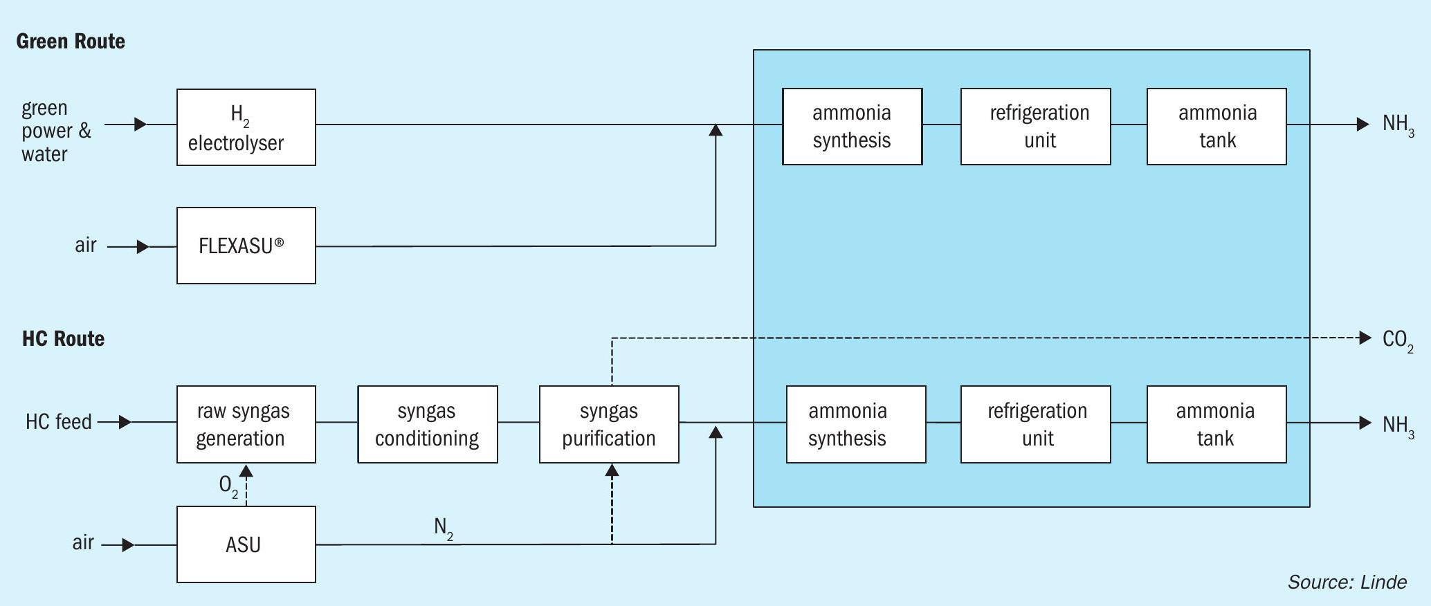
Fig. 3 shows a comparison of green ammonia production versus conventional ammonia production. The hydrocarbon-based block flow diagram is simplified for Linde’s complete LAC™ product family. The “raw syngas generation” block represents a steam methane reformer or a partial oxidation unit, etc. The “syngas conditioning” illustrates any variant of CO shifting and final “syngas purification” represents CO2 removal and/or hydrogen purification (e.g., Pressure Swing Adsorption (PSA), nitrogen wash unit, Rectisol®, etc.)
The hydrogen generation via the HC-based route is more elaborate due to its multiple process units and equipment involved. The electrolyser unit is distinguished as a much simpler way to generate hydrogen due to the ease of feedstock handling, simplified and less process steps.
In the case of green ammonia production, the ammonia syngas is generated by mixing hydrogen from a water electrolysis unit in combination with nitrogen from an ASU.
The main advantage of the Linde Ammonia Concept, the inert free ammonia loop design, is also adopted in the green ammonia generation concept. This design results in several benefits: First, the purge free loop design reduces the size of the synthesis loop and utilises its associated installed equipment and catalyst to their maximum capability. Second, the necessity of purge gas cleaning and recovery is eliminated. Additionally, since less “ballast” gas is circulated, efficiency is increased leading to lower operating expenditures due to energy savings.
An optimised ammonia loop allows for an operational load range from 30 to 100% with a load change rate of 1% per minute. With additional efforts the operating load range window can be further reduced to 10%, and the load change rate increased above 1% per minute.
Energy efficiency
Fig. 4 represents an energy flux diagram for green ammonia production with PEM electrolyser technology starting with renewable power up to liquid ammonia storage at atmospheric conditions.
From the 100% electrical energy input, approximately 61% ends up in the final ammonia product. The overall energy efficiency of the process is almost solely determined by the electrolyser. The largest energy conversion loss (waste heat) with an amount of approximately 30% occurs in the electrolyser unit. The auxiliary systems (e.g., air separation, syngas compression and ammonia refrigeration) consume only 4% of the total energy demand. Within the ammonia synthesis itself, most of the exothermicity is recovered as high-pressure steam which can subsequently be used to assist the synthesis gas compressor drive or other consumers.
The energy number for green ammonia from PEM electrolysis is approximately 8.6 Gcalel /tonne NH3 (10 MWhel /tonne NH3).

Challenges in the design of green ammonia plants
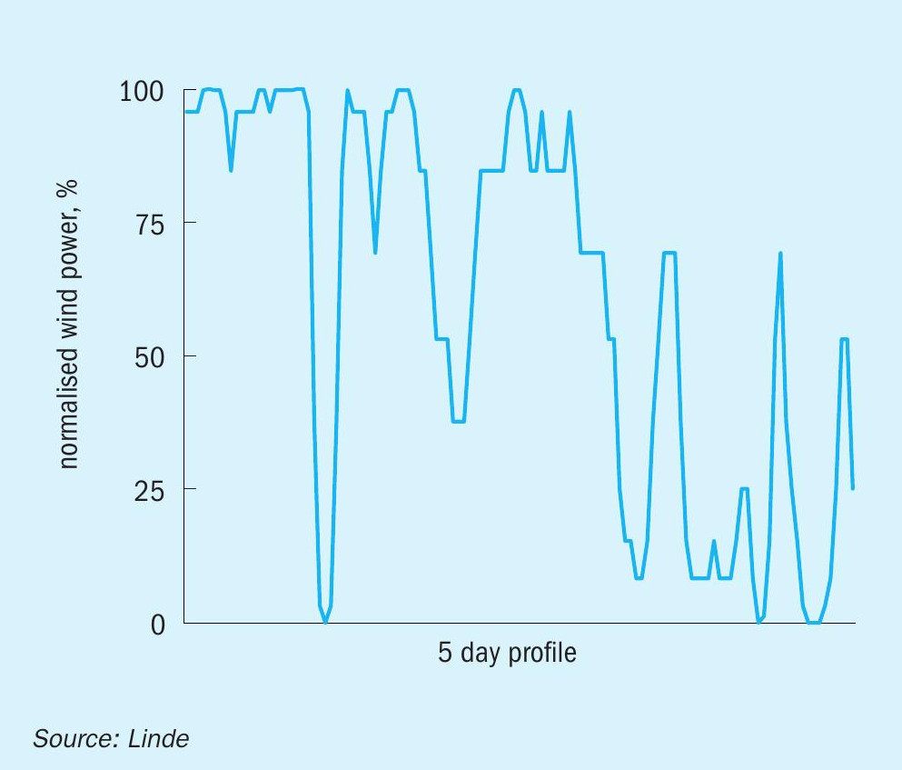
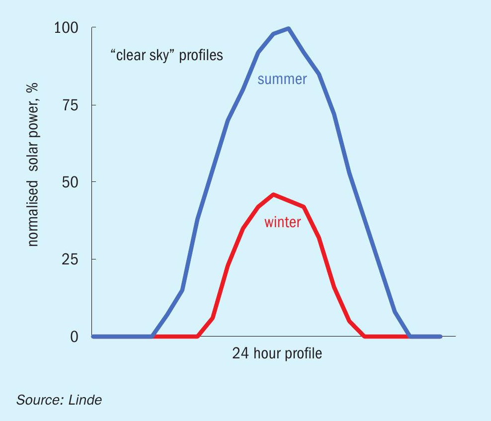
The type of renewable power and its associated reliability must be considered for the design of a green ammonia plant. Fig. 1 shows renewable electric power from hydro and biomass is characterised by a base load quality with regard to availability. In contrast, wind and solar power are distinguished by highly dynamic behaviour. The reason for these highly volatile fluctuations is shown in Fig. 5 for both energy sources. The graph in Fig. 5(a) illustrates a typical normalised wind power profile for a five-day period. The power generation is highly volatile and fluctuating between 0 and 100 %. It is solely dependent on local wind conditions. In Fig. 5(b) a one-day solar power profile during winter and summertime for a “clear sky” is presented. This proves solar power generation depends on daily and seasonal fluctuations, along with, the local weather conditions. From the graphs shown, it can be concluded that the design of plants operating in an island mode or having very limited access to a stabilising grid needs to be adapted to the dynamic power availability profile.
To allow for highly fluctuating power availability, all involved production steps need to be stretched to their maximum operating capabilities. Measures to cope with large dynamic demands include extended turndown ratios, maximised plant load change rates, plant robustness for frequent starts and stops, and “hot/ cold” stand-by operation. Furthermore, the need for a buffer concept for nitrogen and/ or hydrogen could be considered.
In light of the required reduction of greenhouse gas emissions, the production of renewable power generation needs to be increased while fossil fuel power generation is decreased. Green ammonia and/ or hydrogen are reliable chemical energy carriers which could fill this gap.
The advantages of Linde’s technology for each production step towards green ammonia make the Linde Ammonia Concept (LAC™ ) perfectly suitable for green ammonia production applications. Linde has proven references in the design and experience in operation of conventional ammonia plants according to the Linde Ammonia Concept (LAC™ ). Linde can offer the design and full EPC services for green ammonia plants. The appropriate plant set-up, including a potential buffer concept, will be investigated by Linde for each project based on a detailed analysis of all project relevant parameters to deliver the most suitable and economical plant design to the customer.
References
THYSSENKRUPP INDUSTRIAL SOLUTIONS
Green ammonia: Improvements in plant modularisation
Current production routes of ammonia are solely based on the use of fossil fuel feedstocks. This implies, that greenhouse gases in the form of carbon dioxide are emitted from these production facilities. Decarbonisation of the ammonia industry is one vision for the future to drastically reduce the amount of man-made emissions, which are contributing to climate change. One solution is to go for green ammonia, which is synthesised from nitrogen from air separation and from hydrogen obtained from the electrolysis of water powered by renewable energy sources.
Green ammonia plants will typically be installed in locations where the harvesting of renewable energy takes place. These are places where intensive solar radiation, strong and steady wind, enduring water flows or a combination of the three can be found. Unfortunately, the existing infrastructure in some, or most, but not all remote locations is very limited, or even not present, which makes erection of a green ammonia plant a time consuming and costly exercise. One way to overcome this challenge is to shift construction activities away from the original site into fabrication shops or yards. This strategy will offer the following advantages:
- reduced construction time on the final site;
- reduction of risks associated with the construction phase
- less personnel required at site during the construction phase;
- shorter commissioning phase due to pre-cleaned equipment/piping within the modules;
- fabrication of the modules in the best cost countries possible;
- improved quality of the modules due to optimal use of tools in the workshops;
- transportation limits will be overcome with adequate module sizing;
- modularisation offers the possibility to take further advantages of serial production.
Standard sizes for the green ammonia plants have been established at thyssenkrupp Industrial Solutions, for small-scale, mid-scale, large-scale and world-scale applications. For the different capacities, detailed engineering studies have been carried out and 3D models of the plants have been created. A high degree of modularisation and pre-fabrication was aimed for in the layout to optimise the installation process. The module size for the small-scale plant corresponds to a 40-ft standard container that can be shipped over a large distance but can also be transported by truck via ordinary roads to its final destination. The pipe racks connecting the individual plant sections are also designed entirely as modules. Almost the entire Haber-Bosch synthesis gas loop can also be completely accommodated in a reasonable number of modules. This also applies to many units related to offsites and utilities, such as the complete desalination or instrument air system. Other plant components are less suitable for modularisation due to their dimensions or weight, such as the site fabricated tanks or the flare stack. The fact that the modules can also be placed on top of each other additionally reduces the plot space required for the plant.
TOYO ENGINEERING CORPORATION
TOYO green methanol for a carbon recycle society
Toyo Engineering Corporation (TOYO), a global leading engineering contractor, has established a carbon recycling strategy based on its own technology or collaboration with partners. g-Methanol® (green methanol technology) is one of the solutions offered by TOYO for CO2 utilisation. TOYO has extensive experience as a licensor of the methanol process derived from fossil fuel feedstocks. Based on this experience, TOYO has established a new concept, g-Methanol®, which is derived from green H2 and CO2 to meet today’s sustainability challenges.
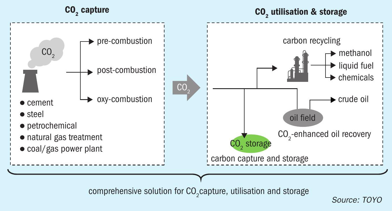
Carbon capture utilisation and storage (CCUS) is an important CO2 emissions reduction technology. A key feature of CCUS is carbon recycling, utilising the CO2 as a resource to create valuable products and to realise a carbon neutral society. Fuel production from captured CO2, so-called e-fuel, is expected to be a promising route to consume large amounts of CO2. Although methanol is also categorised as an e-fuel, its applications extend much further as it is also a raw material for olefin production and other chemicals.
TOYO’s carbon recycle strategy
Reducing CO2 emissions to prevent global warming is a common goal for all humankind. With the ambition to achieve a carbon-neutral society, TOYO is working to provide a wide range of solutions, including technology and business development support, ranging from the capture of CO2, to the utilisation and storage of CO2 (CCUS), through collaboration with partners with advanced technologies and through TOYO’s expertise established in the plant engineering business (Fig. 1).
CO2 utilisation and storage technology
TOYO’s solutions for CO2 utilisation and storage technology include:
- e-fuel (g-Methanol® and sustainable aviation fuel)
- CO2 EOR
Future outlook of methanol market
The demand for environmentally friendly fuels and derivatives such as olefins is expected to drive future methanol demand.
Methanol-to-olefins (MTO)
MTO is olefin production technology from methanol. In Japan, the GI (Green Innovation) Fund was established by METI (Ministry of Economy, Trade and Industry) to achieve carbon neutrality by 2050. Alcohol to olefins has been recognised as one of the R&D themes to retrofit production systems1, whereby part of the olefins are produced from alcohol derived from green H2 and CO2 instead of fossil fuel pyrolysis. Methanol has the potential to play a key part in the production of olefins.
Drop-in fuel
Methanol is used as a marine fuel, an alternative to gasoline, as well as a gasoline fuel blend for automobiles. Methanol as a marine fuel and ship fuel is already a proven technology. MAN Energy Solutions has developed methanol engine technology for ships and some tankers are already operating commercially in the world. In 2020, A consortium including Maersk, the world’s largest container line, announced plans to develop an industrial-scale production facility to produce renewable marine methanol2 . DME (dimethyl ether) is also produced from methanol. DME has the possibility to be used as an alternative to LPG (liquid propane gas) and diesel fuel. TOYO has developed indirect DME production technologies by adding the DME synthesis process to the methanol plant.
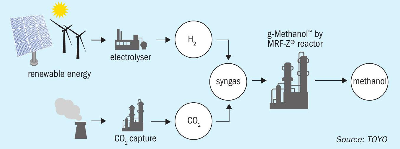
g-Methanol®
TOYO has a long history in methanol production and has now developed a new concept called g-Methanol®, a methanol production process with feedstocks that combine H2 derived from renewable energy with CO2 from exhaust sources, biomass and air (Fig. 2).
Direct CO2 to methanol synthesis
There are some important differences for the direct CO2 to methanol synthesis process compared to the conventional process.
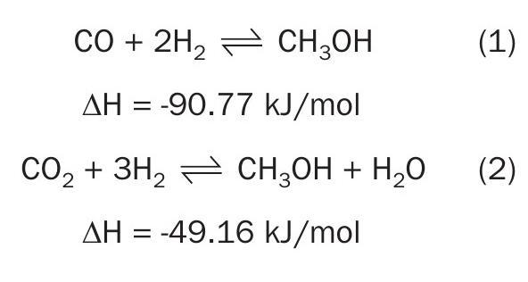
In the conventional process it is important to remove the reaction heat from reactions (1) and (2) below. The reaction heat from the direct CO2 to methanol synthesis (2) is lower than that from synthesis gas (1) and (2), however effective heat removal is still required for optimal operation.
A Cu/ZnO/Al2 O3 -based catalyst is utilised for low-pressure methanol synthesis in conventional plants. However, water produced during methanol synthesis from a CO2 -rich feed can accelerate the crystallisation of Cu/ZnO/Al2 O3 leading to deactivation of the catalyst.
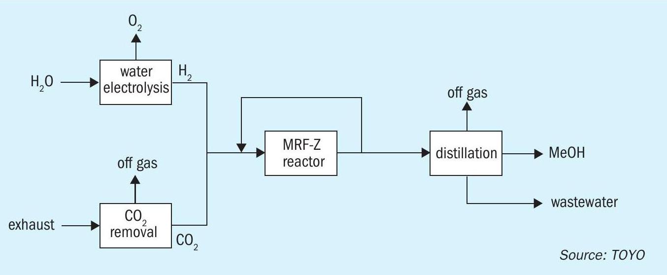
g-Methanol® process flow scheme
Carbon dioxide and hydrogen from battery limits are pressurised to required pressure for methanol synthesis. The mixture of recirculated gas and fresh make-up gas is preheated and introduced to the methanol reactor (MRF-Z® reactor). In the reactor, the methanol synthesis reaction, which is exothermic, takes place at low temperature over a methanol synthesis catalyst. The reaction heat is recovered by boiler water. The reacted gas containing methanol leaves the methanol reactor. After cooling by feed gas and cooling medium, methanol and water are condensed and separated at the knockout drum. Non condensed gas is recycled to the methanol reactor. Methanol and water are sent to the distillation column, and methanol is produced at top of the second distillation column (Fig. 3).
TOYO’s technology solutions for the direct CO2 to methanol synthesis process are summarised below.
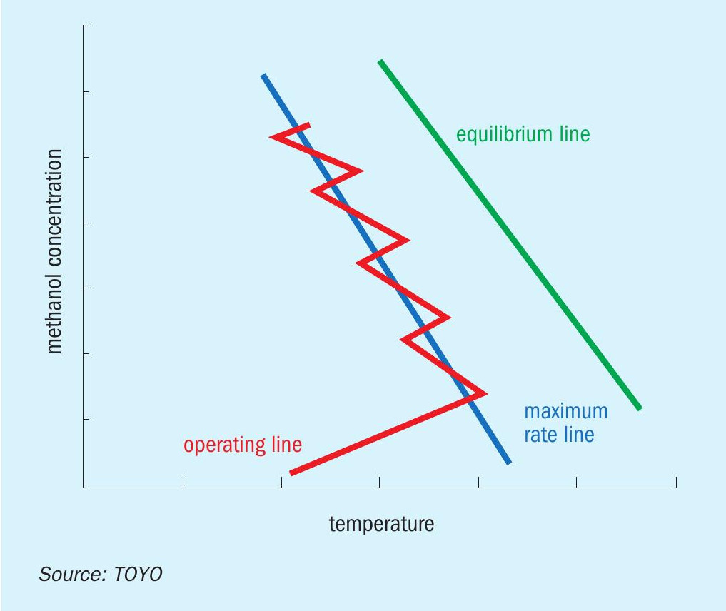
MRF-Z® reactor: TOYO’s proprietary methanol synthesis reactor minimises the catalyst volume by using multi-stage indirect cooling. Although the reaction heat is lower than in the conventional process, suitable heat removal is still key to produce methanol from CO2 with minimum catalyst volume. Thanks to multi-stage indirect cooling, the temperature profile in the catalyst bed is optimised by a suitable cooling tube arrangement using a proprietary simulator developed by TOYO. The optimised temperature profile results in the maximum reaction rate in all areas of the catalyst bed to realise methanol production with minimum catalyst volume (Figs 4 and 5).
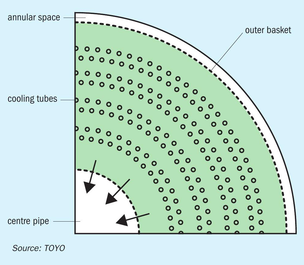
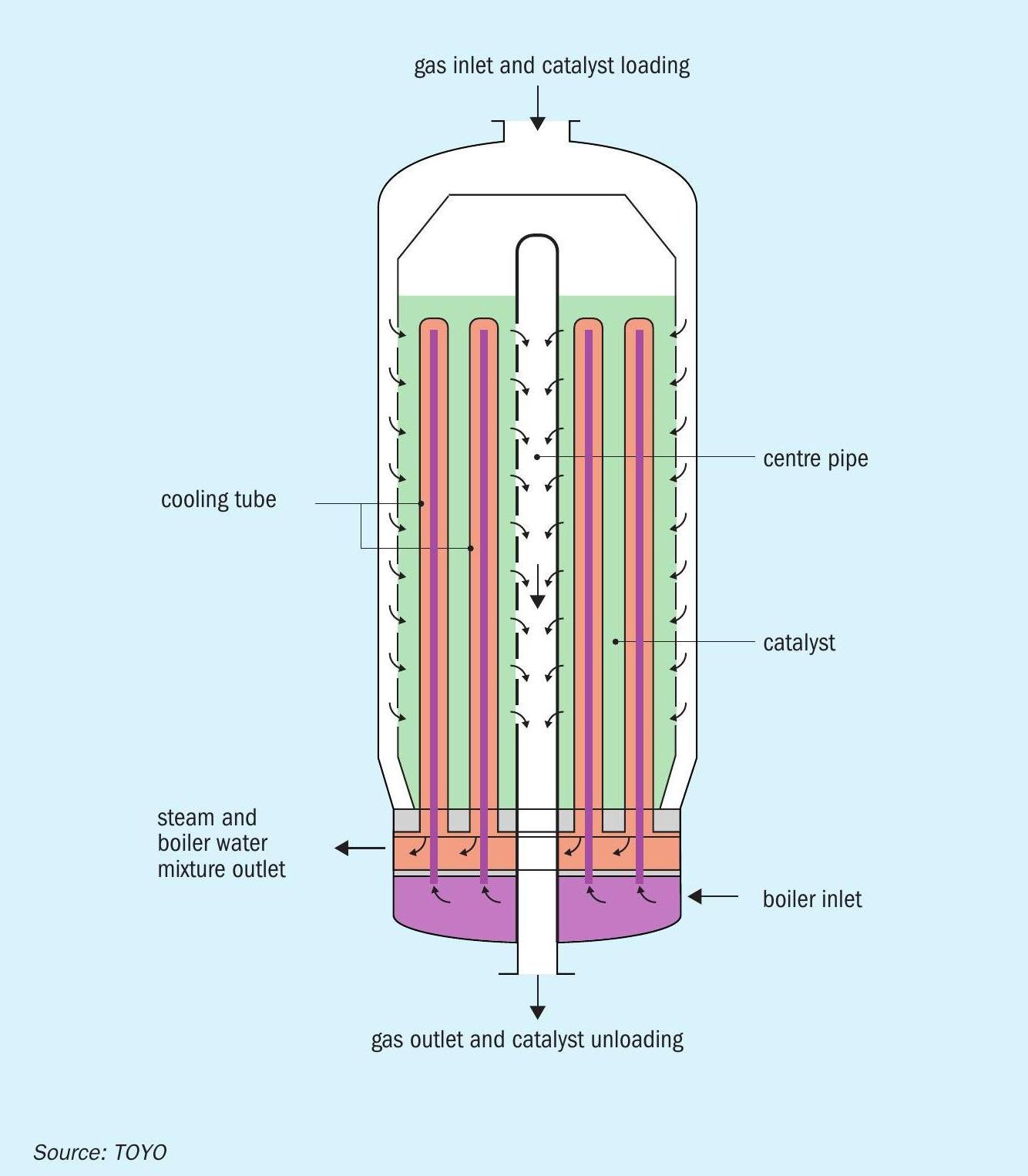
Easy catalyst loading and unloading: With a shorter catalyst life compared to the conventional process, easy catalyst replacement is necessary. The features of the MRF-Z® reactor (Figs 6 and 7), shell-side catalyst loading and bayonet boiler tubes and TOYO’s proprietary mechanical design, provide for easy maintenance.
Other features include:
- shell-side catalyst/wide range single train capacity;
- steam raising methanol reactor/best use of surplus heat;
- cross flow to cooling tubes/maximum heat transfer;
- radial gas flow/low pressure drop;
- bayonet boiler tubes/no thermal stress.
New developments of the methanol synthesis catalyst are an important part of the CO 2 to methanol process. The main goals for the catalyst are to have higher activity and a longer lifetime because of the lower equilibrium conversion at the same pressure and temperature conditions and due to the deactivation of Cu/ZnO/Al 2 O 3 catalyst from water. 3
The development of methanol synthesis catalysts using CO 2 as a raw material has been actively carried out by many research institutes since around 1990. 3 The basis of the development was Cu/ZnO/Al 2 O 3 used as a conventional methanol synthesis catalyst, which improves the reaction activity at low temperatures and at the same time improves the durability of the catalyst against water produced as a by-product during the reaction. The catalyst has been studied with the goal to increase the activity and lifetime of the catalyst. In addition, research on methanol synthesis catalysts using metal catalysts other than copper-based catalysts is also being conducted. Recently, major catalyst suppliers have released methanol synthesis catalysts for CO 2 to methanol.
Activity in Japan
The world’s first CO 2 to methanol plant has already been commercialised by CRI (Carbon Recycling International) in Iceland. In addition, Liquid Wind has announced its plans to build an e-methanol plant in Sweden. In Japan, a pilot scale project was started in 2008. The following projects are either completed or scheduled:
MCI CO 2 -to-methanol project
MCI (Mitsui Chemicals) took part in the CCU project led by the Research Institute of Innovative Technology for the Earth (RITE), commissioned by NEDO (New Energy and Industrial Technology Development Organization), and developed a high activity catalyst. Refinement of this highly active catalyst has been tested in a pilot plant using CCU technology at MCI Osaka Works in 2009. 4
Research into effective recycling of CO 2
A research project supported by NEDO 5 is scheduled to look into the effective recycling of CO 2 by converting it into core materials such as methanol at CO 2 storage points in the city of Tomakomai in Hokkaido, Japan. CO 2 captured from the refinery will be utilised as a raw material for the production of methanol. In this study, the following will be evaluated:
- basic design considering the interaction of the entire plant;
- evaluation of each component equipment;
- economic feasibility evaluation;
- examination of related technology.
MGC circular carbon methanol
MGC (Mitsubishi Gas Chemical) has announced plans to launch methanol production using CO 2 and H 2 at the Niigata plant pilot facility (CO 2 throughput: approximately 1.5 t/d).
References
“We are excited to move forward with the world’s first fully dynamic industrial-scale renewable ammonia plant as it highlights the viability of electrification beyond the power sector.”
Ole Kiil Nielsen, Vice President and Head of Power-to-X Solutions at Vestas.
SKOVGAARD INVEST, VESTAS AND HALDOR TOPSOE
World’s first industrial dynamic green ammonia demonstration plant
Green ammonia, produced from renewable energy, is an excellent fuel and fertilizer that can potentially replace significant volumes of fossil fuels and help accelerate the transition to a world powered by renewable energy. The cost of green ammonia is currently significantly higher than that of comparable ammonia from fossil fuel so to improve the business case and increase the attractiveness of green ammonia as a substitute for fossil fuels, a partnership of industry leaders is building the first-of-its-kind green ammonia plant at the commercial scale of 10 MW power, based on a dynamic, scalable, and cost-optimised solution. Clean power from wind turbines and solar panels will be connected directly to the electrolysis unit, making it more cost-effective than involving a battery or hydrogen storage. The plant will be located in Western Jutland, Denmark, and will produce more than 5,000 tonnes of green ammonia from renewable power each year. This production will prevent 8,200 tonnes of CO2 from being emitted into the atmosphere every year. The plant is expected to be operational by 2023.
The project has been developed by Skovgaard Invest, supported by Vestas, a global leader in sustainable energy solutions, and Haldor Topsoe, a global leader in catalysts, technology, and services for the chemical and refining industries. The partnership will jointly invest in the project. In addition, the Danish Energy Technology Development and Demonstration Program (EUDP) has awarded funding for the green ammonia project of 81 million DKK (app. e11 billion).
The parties will design the plant’s dynamic ammonia technology to secure optimal production and adapt to the inherent fluctuations in power output from wind turbines and solar panels. The ammonia plant will interface to a green hydrogen solution, integrating electrolysis with wind and solar in one smart control system. In addition, the renewable energy generation will be connected directly to the national grid so surplus power can be sold to the grid.
12 MW existing V80-2.0 MW Vestas wind turbines and 50 MW new solar panels will power an electrolyser unit that will produce hydrogen which will subsequently be processed into ammonia. Such processes are commonly referred to as “Power-to-X”. Green ammonia has huge potential in the global effort to substitute fossil fuels with sustainable alternatives. It has been highlighted as a superior green fuel for international shipping that currently accounts for around 2% of global energy-related CO2 emissions.
When in operation, this lighthouse project will deliver proof of concept and experience that can pave the way for larger Power-to-X projects in the future. The project has been specifically designed to provide the necessary know-how and operational experience to upscale the dynamic ammonia plant in new projects.
STAMICARBON
A leap forward for industry sustainability
The world’s transition towards a carbon neutral society also involves the fertilizer industry, where conventional production processes must be redefined to reduce their environmental impact. Maire Tecnimont Group launched its sustainability strategy in early June this year, inspired by the United Nations Sustainable Development Goals, developed through a concept of innovation that is technological, economic, and social. Maire Tecnimont intends to position itself as an enabler of the energy transition worldwide, focusing on people and their well-being and the communities of the geographies in which the Group operates.
From this perspective, Stamicarbon, the Group’s innovation and licensing company, is determined to be part of the change with innovation and investment in sustainable, carbon-free fertilizer production. Its recently introduced Stami Green Ammonia technology package makes it possible to produce ammonia from renewable energy sources. The resulting green ammonia can then be used to produce green nitrate-based fertilizers.
How green ammonia is produced
The most common industrial way to produce ammonia is the Haber-Bosch process, which uses nitrogen from the air and derives hydrogen from hydrocarbons, most commonly natural gas, through a conversion process of steam reforming (Fig. 1).
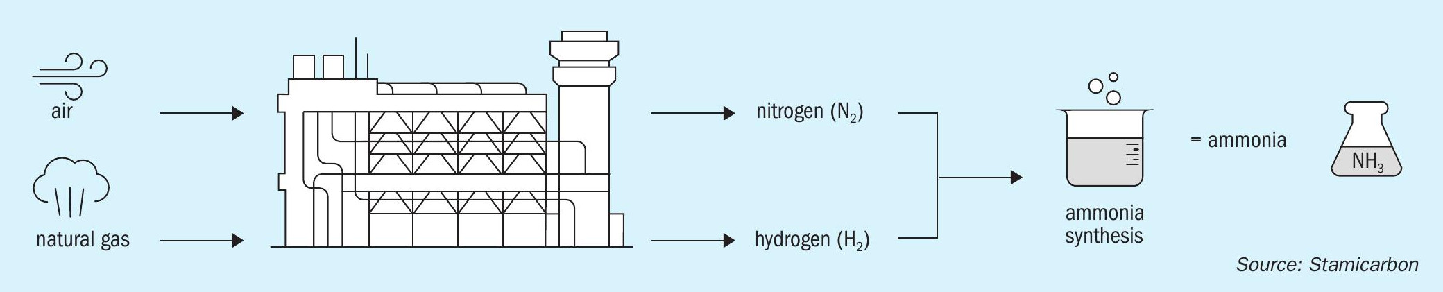
Since fossil fuels are used as feedstock for ammonia production in the first step of the process, carbon monoxide is produced alongside hydrogen. While hydrogen continues further into the synthesis, carbon dioxide, having no other role, is mainly released into the atmosphere. The output of this production process is known as “grey” ammonia.
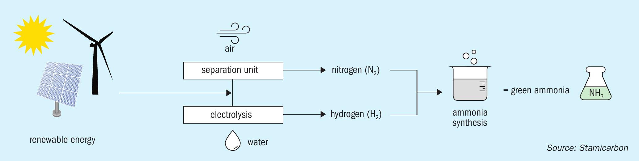
Green ammonia technology offers a more sustainable alternative by eliminating carbon from the process. In it, water electrolysis is used to derive hydrogen, nitrogen is added from the air, and the rest of the production process is powered by renewable energy sources. Using electricity, water is separated into hydrogen and oxygen, no fossil fuels involved, while electricity is derived from renewable sources like solar, wind, water, and geothermal energy (Fig. 2).
In short, with Stamicarbon’s green ammonia technology package, ammonia can be produced with nature’s elements like sun, air and water, resulting in a sustainable, carbon-free output. Of course, since the plant operates on renewables, it needs a constant supply of energy, so the location needs to be considered carefully – it is best to build a green ammonia plant near the energy source to optimise the financial model. But it is also possible to obtain electricity by connecting the plant to a green energy grid or hydropower, while carbon-free nuclear power could also be considered.
Technology features of Stami Green Ammonia
A Stami Green Ammonia plant uses renewable energy sources to power ammonia synthesis instead of fossil fuels, offering a viable solution for tackling the global carbon challenge. The technology configuration, characterised by a modularised approach and thus perfect for small-scale facilities, is the first of its kind, based on proven technology.
The technology package is available in proven design capacities for small-scale plants – 100 t/d, 200 and 250 t/d of ammonia production – but can be scaled upwards. A Stami Green Ammonia plant has a lean and compact design, with a footprint of approximately 15 x 30 m, including the compressor building, and uses about 35-100 MW of power, depending on capacity (Fig. 3).
Recent technological developments in the fertilizer industry have focused more on economy of scale and fertilizer production of higher outputs. However, now that the industry is moving towards greener technologies, the availability of renewable electricity, limitations in electrolyser production capacity and lack of economy of scale thereof must be considered, and these are not yet sufficient to facilitate large-scale projects at short notice. Secondly, existing technology is not yet ready to efficiently manage the intermittency of renewable feedstock required for standalone largescale green ammonia production.
Stami Green Ammonia has four recently commissioned operating technology references based on natural gas. This is the strongest technology reference in a small-scale range that makes a sound basis for further development of the future small-scale ammonia plant concept.
The technology includes the following key features:
- high capex efficiency;
- strongest reference base with four small-scale plants in operation;
- lean, compact and modularised design;
- high plant reliability with a proven track record;
- compliance with highest environmental standards.
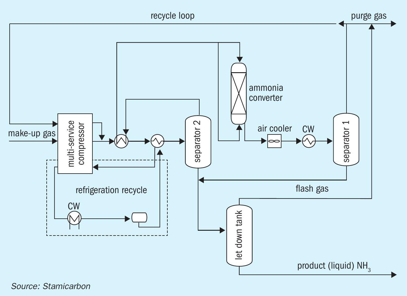
The main technological feature of Stami Green Ammonia is the use of a high-pressure ammonia synloop (approximately 300 bar), which has been customised to make the most efficient plant design at a small scale and with green feedstock. This design choice allows ammonia to be condensed with the cooling water, eliminating the need for a refrigerating compressor. As a result, the plant operates with a single proven and reliable electric-driven reciprocating multiservice compressor. The minimal equipment needed for plant operations leads to substantial capex saving, which is an important consideration for small-scale applications.
The technology package offers a competitive solution for local production on a small scale and can be applied in combination with Stamicarbon’s existing (monopressure and dual-pressure) nitric acid and urea technologies, moving from grey ammonia to green ammonia-based fertilizers to produce green nitrate fertilizers. In combination with the use of recycled or recovered CO2 , it reduces the carbon intensity of urea fertilizer production. Stamicarbon is also ready to apply its green ammonia technology to other industries, such as steelmaking, to help make them more sustainable.
Renewable power-to-fertilizer project in Kenya
The first commercial application of Stami Green Ammonia will take place at the Oserian Two Lakes Industrial Park in Kenya, a 150-hectare sustainable development project in Nakuru County, 100 km from the capital Nairobi. Stamicarbon will contribute both its green ammonia and its nitric acid technologies to the renewable power-to-fertilizer plant project, working alongside Maire Tecnimont Group’s subsidiaries MET Development (the Project Development Company) and NextChem (the company for the development of technologies for green chemistry and energy transition), to build the world’s first commercial nitrate fertilizer plant operating at an industrial scale (approx. 200 kt/a) powered by renewable sources of energy.
The plant will be powered primarily by geothermal and solar energy, using about 70 MW of renewable power, which will allow for a yearly reduction of 100,000 t of CO2 , compared to a fertilizer plant powered by natural gas. Preliminary engineering works have already begun, and NextChem plans to start the front-end engineering design (FEED) by the end of 2021. The objective is to start commercial operation of the plant in 2025, producing 550 t/d of calcium ammonium nitrate (CAN) and fertilizers based on nitrogen, phosphorus, and potassium (NPK) to meet the demand of local agricultural requirements. The green power-to-fertilizer plant at the Oserian Two Lakes Industrial Park will become the first of its kind and support local fertilizer production in Kenya, securing the availability of fertilizers at the right time in the agricultural season.
The second commercial application of Stami Green Ammonia
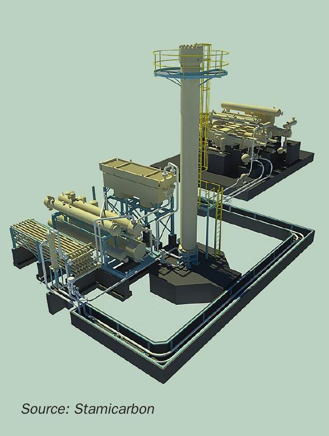
In September 2021, Stamicarbon, NextChem and MET Development signed an agreement with Greenfield Nitrogen LLC to develop the first dedicated green ammonia plant in the US Midwest. The 240 t/d plant will be based on Stami Green Ammonia technology provided by Stamicarbon (Fig. 4), while NextChem will start a feasibility study, and MET Development will assist with project development. This is already the second commercial Stami Green Ammonia plant under development since the technology entered the market in May 2021.
The new plant, to be located near Garner, Iowa, will be the first of Greenfield Nitrogen’s green ammonia facilities in the US Corn Belt, the region in the Midwest widely known for its production of corn. This new plant will be powered by renewable energy resources and will produce around 83,000 t/a of ammonia, reducing the region’s dependency on imported ammonia. It will also contribute to reducing CO2 emissions by the industry, expected to save over 166,000 t/a of CO2 emissions.
Green ammonia for European green initiatives
Besides the direct development and licensing of new commercial green ammonia plants, Stamicarbon is also participating in two European green initiatives to make the industry more sustainable.
The first one is an EU-funded project INITIATE (Innovative industrial transformation of the steel and chemical industries of Europe) to use the carbon-rich off-gases from steel mills as feedstock for urea production. At the core of this process is a modular carbon capture utilisation and storage (CCUS) technology, which allows for integrating the conditioning of steel gases with ammonia synthesis. Stamicarbon will be responsible for the commercial implementation plan and supply its green ammonia technology to justify the pilot project’s viability and prove the capability to produce ammonia to build a reference plant for urea production in the next stage. In addition, it will supply the ammonia technology license and ammonia converter for the 3 t/d pilot plant in Luleå, Sweden.
The second initiative is Stamicarbon’s application of its green ammonia technology to PROMETEO, a European Horizon 2020 project with the aim to develop an innovative prototype for high-temperature electrolysis, using renewable energy to power the continuous production of green hydrogen. The innovative solution will address intermittency in the solar power supply by managing energy conversion and re-generation phases. Green hydrogen produced in this way will contribute to the production of green ammonia and green fertilizers.
Future-proof ammonia production
The world is demanding accelerated cooperative climate action to reduce emissions. At the same time, feeding the ever-growing population remains a challenge. Stami Green Ammonia aims to serve as a gateway to carbon-free and future-proof green ammonia production, representing a significant leap for sustainability within the fertilizer industry, while also offering exciting opportunities for collaboration between the fertilizer and energy markets.