Nitrogen+Syngas 376 Mar-Apr 2022
31 March 2022
Steam methane reformer assessment and optimisation
STEAM REFORMER SERVICES
Steam methane reformer assessment and optimisation
New innovations, services and latest technologies to improve the operation and reliability of steam methane reformers from AMETEK Land, Kontrolltechnik, BD Energy Systems, Koch Engineered Solutions, and Quest integrity.
AMETEK LAND
Optimising steam methane reformers to increase load, process efficiency and reduce downtime
Steam methane reformers (SMRs) are among the largest and most carbon-intensive fired heaters and are widely used in the hydrocarbon processing industries for the production of important gases – particularly hydrogen, methanol, and ammonia.
The steam reforming process requires a large primary reformer, heating many tubes containing a catalyst. When steam and natural gas are passed through the tubes and over the catalyst, synthetic gas (syngas) – a mix of hydrogen and carbon monoxide – is produced, and then used in the production of the desired product.
Maintaining temperatures below design limits avoids heat damage to the reformer tube, while ensuring good product yield. These temperature measurements are taken using infrared pyrometers. Infrared technology can be significantly affected by combustion products including steam, carbon dioxide (CO2 ) and other hot gases, so wavelengths should be chosen according to the furnace atmosphere. Changing emissivity within the tube must also be considered.
Accurate temperature monitoring is essential to ensure maximum efficiency – reducing emissions of CO2 – save energy costs, extend the lifespan of the reformer tube, and improve operator safety. However, any solution must overcome the challenging process conditions, while a non-contact measurement is needed to withstand the high temperatures involved.
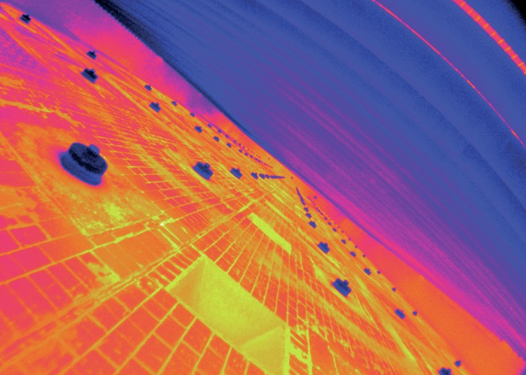
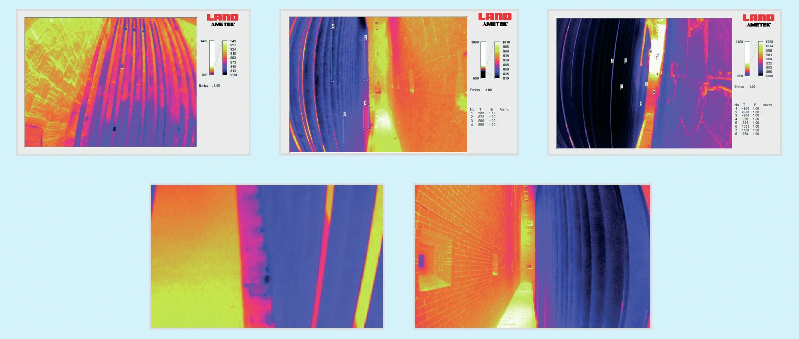
Fig. 1 shows a thermal image of a side fired SMR.
Portable and fixed non-contact measurements
Many plants operate conservatively to reduce the risk of material failures. However, even running at 10°C (18°F) below design temperatures typically results in a 1% productivity loss on an SMR.
Depending on the furnace design, if the pyrometer measurements show that SMR temperatures are approaching or surpassing the tube’s design limits, firing can be reduced, burners can be gagged or, in extreme cases, burners may be shut off.
Since this is a labour-intensive, reactive approach, potentially concerning conditions are usually only be acted upon if observed and recorded by the inspection team.
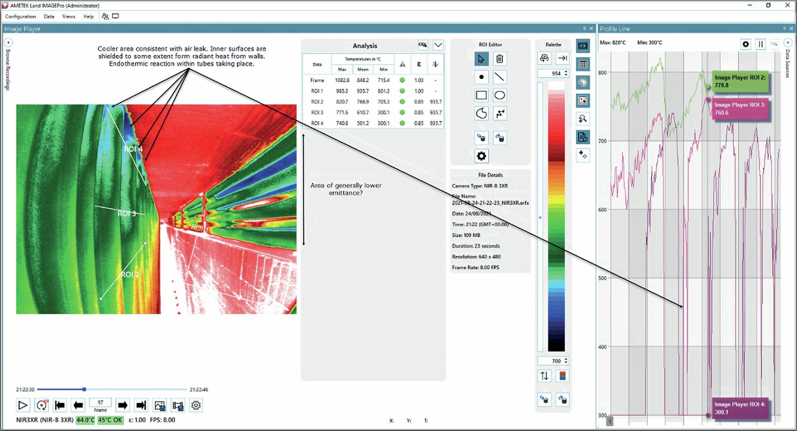
Portable and fixed thermal imaging systems can both be used to produce high-resolution images or videos, and extensive temperature data in the SMR. However, while portable systems are valuable inspection and thermal survey tools – and can often see parts of the SMR that operators may not be able to see with the naked eye through peep-doors – the single-point, manual data collection they provide does not match the volume of information that can be supplied by a thermal imaging system.
Fixed thermal imager-based monitoring systems provide this comprehensive data in real-time, with automated image analysis and continuous monitoring of tube wall temperatures. They can also identify insulation, burner tip/tile condition, and potential hot bands or catalyst issues on SMRs. The continuous surface temperature data allows remaining tube lifetime to be calculated.
“Accurate temperature monitoring is essential to ensure maximum efficiency, save energy costs, extend the lifespan of the reformer tube, and improve operator safety.”
A thermal imager using a borescope can take measurements through a small hole in the furnace wall, causing far less interference with the process than an open peephole.
A wide-angle field of view allows measurement of multiple reformer tubes simultaneously, delivering a real-time, high-resolution image with tens of thousands of individual temperature measurement points.
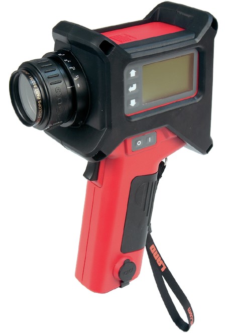
AMETEK Land’s recommended solution for thermal imaging in SMRs is the NIR Borescope (NIR-B) 640-EX, a short wavelength radiometric infrared borescope imaging camera which measures temperatures in the single range 600 to 1,800°C (1,112 to 3,272°F) and utilises the latest wide dynamic range imaging technology.
This is ideal for industrial gas applications where high differential temperatures exist in the field of view, such as tube and furnace walls.
Other measurement solutions
AMETEK Land offers a Portable Furnace Thermal Imaging System (Fig. 3), with optional air-cooling, that enables regular, easy, and quick inspections, along with thorough temperature data that can be analysed and archived (Fig. 4).
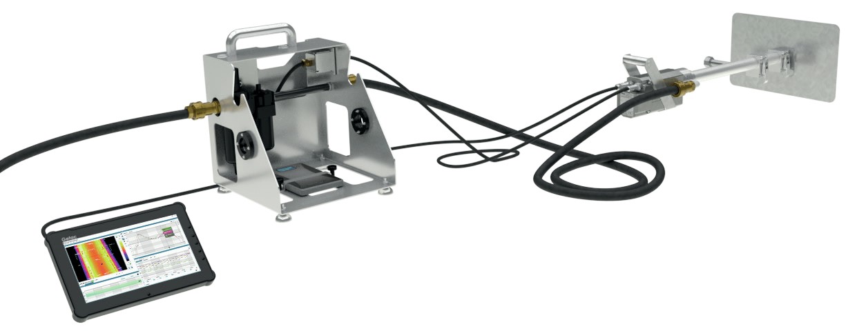
The system is available with a range of multiple wavelengths, borescope lengths, and Fields of View (FoV), ensuring it is suitable for many petrochemical processes. The wavelength must be correct for the gas atmosphere; the borescope should extend through the peep-door comfortably, and the FoV should match the peep-door design and tube layout.
Portable pyrometers and thermal imaging systems provide repeatable data, but reference measurements are also required to verify the accuracy of the temperature data produced.
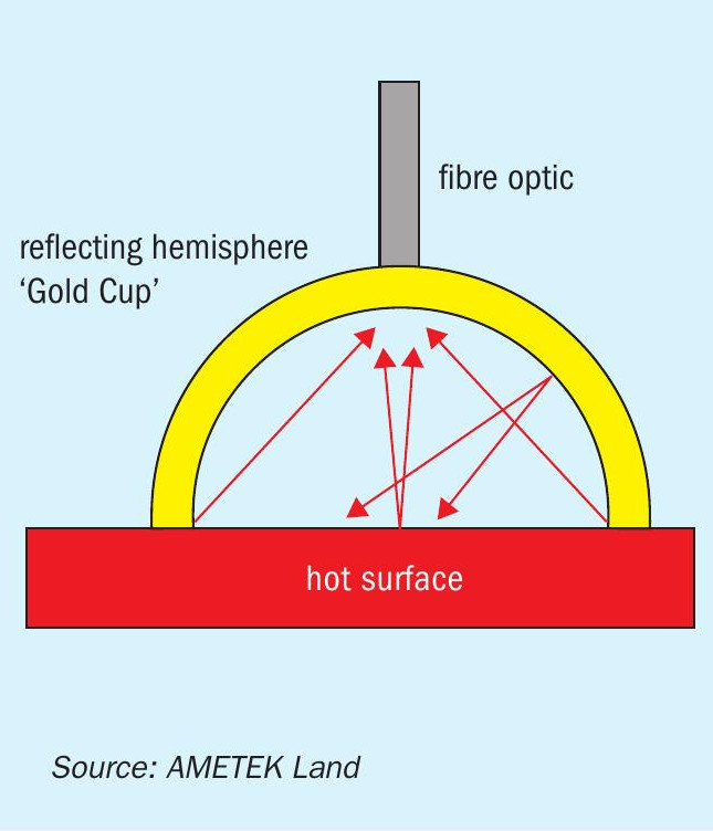
For this, AMETEK Land provides the Gold Cup (Fig. 6), a water-cooled threemetre-long probe that creates near black body conditions at the measurement point,ensuring repeatable, reliable reference temperatures.
If the environment has a hotter background – as is usually the case in an SMR – compensation for both surface emissivity and incident radiation is needed to ensure accurate non-contact infrared measurements. Designed only for periodic reference measurement readings, the Gold Cup uses a hemispherical reflector to deliver a measurement which is independent of emissivity and incident radiation.
Case study
Air Liquide, the world leader in gases, technologies and services for industry and health, employed AMETEK Land’s NIR-B-640-EX thermal imager to continuously measure the temperature of tube walls within its SMRs.
The SMRs are used to produce hydrogen and carbon dioxide industrial gases, and their reliable, safe operation is of paramount importance. However, they are very challenging assets to maintain and operate.
Some of the common problems in reformer operation are burner, flue gas distribution and catalyst issues (Fig. 5), which can all directly affect Tube Wall Temperatures (TWT), overall tube lifespan, and cause premature tube failure. They can also lead to excessive caution over TWT, resulting in valuable production being lost annually.
Air Liquide required a solution to deliver a highly accurate and more complete measurement of the equipment and process, compared to spot temperature measurements, capable of operating in a hazardous environment.
AMETEK Land’s NIR-B-640-EX provides a high-resolution thermal image with real time high accuracy temperature measurements of both the tube wall and refractory wall surface, allowing for background compensation.
It was developed specifically to operate in the hazardous environment of an SMR and is ATEX and IECEx approved, and CSA certified.
Air Liquide initially undertook a live trial of the NIR-B-640-EX at one pilot plant, with the full support of AMETEK Land’s team in Spain. This enabled the operators to fully test the instrument within their specific, harsh environment.
Through this testing, Air Liquide confirmed the thermal imager’s suitability, demonstrating the critical role it could play in enabling and enhancing understanding of tube conditions.
The borescope was installed through the furnace wall in front of the tubes within the chamber. Via a field connection box, the thermal imager is connected to the control room.
Air Liquide’s main drivers in investing in the NIR-B-640-EX were to extend tube and catalyst life, which was achieved as a result of the testing. Continuous data relating to the SMR which enabled correct balancing and monitoring of their main, critical asset.
Extensive functions available within the system’s thermal imaging software enabled continuous monitoring of TWT, and early warning of any increasing temperature, allowing Air Liquide operators to spot and respond immediately to problems such as hot spots and bands on the tubes, refractory damage, and any flame impingement.
With the furnace know-how provided by the NIR-B-640-EX’s continuous temperature monitoring, the operators are able to make much more informed and confident decisions for greater plant reliability.
KONTROLLTECHNIK INSPECTION SERVICES
Using technology to protect the heart of the plant
Thermal surveys
The first technology to be discussed is thermal surveys using an IR camera. Reformer surveys are performed during operation to give the user an overview of how the reformer is preforming and highlight any issues found during the survey. This survey helps to identify problem areas within the radiant box, issues for example such as flame impingement on the reformer tubes, burner issues, catalyst issues within the reformer tubes, and flue-gas distribution issues. All of these issues can cause overheating of the tube surface, which in turn will negatively affect the life of the tube and could cause premature tube failure.
During a survey, infrared images are taken from view ports into the reformer of the tubes, reformer walls, burners, and tunnels within the radiant box. These images are stored and then analysed in a software program. From these images a report will be produced to discuss with the client. The report will highlight issues found during the survey and also show the areas where the process is working as expected. The goal of the survey is not just to identify problems but also give the operators the data to help balance the reformer. Regardless of how the reformer is operated either below or at design levels, it should always be a priority to operate a balanced reformer. By maintaining a balanced reformer this will help to make future maintenance and turnarounds more efficient and less costly.
Reformer pipe scanners
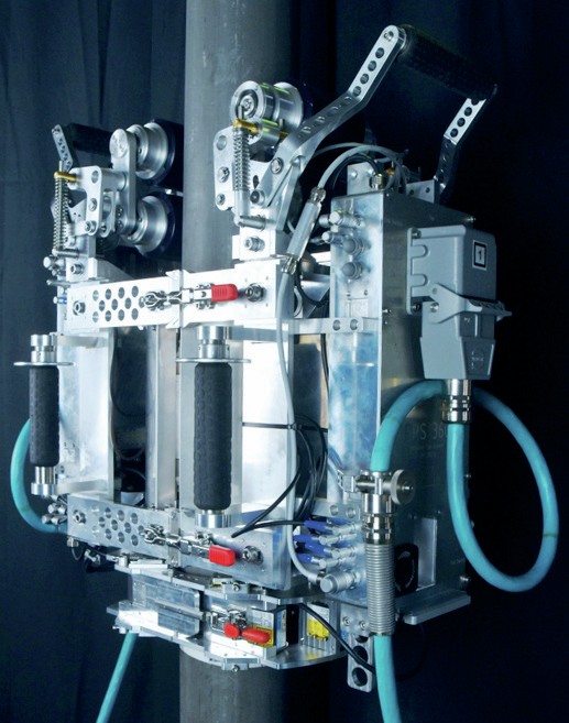
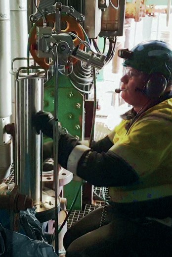
For inspection of reformer tubes during a shutdown KontrollTechnik has developed an innovative robotic dual technique NDT Scanner the “Reformer Pipe Scanner 360” (Fig. 1). There are two scanners the RPS-360-ID and the RPS-360-OD, both scanners use the dual technique of eddy current for crack detection and laser measurement for expansion.
The Reformer Pipe Scanner type RPS360-ID is equipped with a powerful proprietary hybrid NDT technique for sensitive crack detection in reformer tubes up to 23 mm wall thickness. As the proprietary technique needs no couplant, the readings are repeatable from inspection to inspection. The inspection tool was developed to inspect reformer tubes from below the floor to the top of each tube to give complete inspection for creep and crack damage of each tube.
The diameter measurement results of the 360° laser for creep detection is performed simultaneously to the powerful proprietary technique testing in a 3-dimensional overview of each tube. The laser rotates thus giving a complete profile of the inside of the tube. As the inside of the tube is a machined surface this permits a more accurate expansion measurement and allows problem areas to be detected much earlier than traditional methods of inspection (see Fig. 2).
Inspecting from the internal surface RPS-360-ID
Inspecting from the internal surface, the complete unit will be moved by a remote-controlled puller/pusher unit allowing the passage from the bottom of the tube to the roof assuring a fast and reliable inspection. The key benefits are:
- the only system offering 360° crack detection and 360° laser scan of entire tube length;
- accurate, robust, and reliable by computer-controlled data acquisition;
- powerful proprietary technique for sensitive crack detection;
- integrated rotating laser module for expansion measurement;
- high rate of inspection speed;
- accurate location and sizing of features;
- high repeatability allowing indication monitoring;
- on-site reporting.
The latest and most advanced technology for inspecting reformer tubes is now being introduced as the RPS-360-OD (see Fig. 3) an external automated scanning system that is equipped with a powerful proprietary hybrid NDT technique for sensitive crack detection in reformer tubes up to 23 mm wall thickness that inspects truly 360° around each tube. As the proprietary technique needs no couplant and is not dependent on tube cleanliness, the readings are repeatable from one inspection to the next inspection.
The diameter measurement inspection system is performed by using multiple lasers for creep detection and diametric growth. Both procedures are performed simultaneously to the powerful proprietary inspection technique at a fast rate. The laser modules are mounted on both sides of the scanner. By differential measurements a maximum of accuracy for the diameter measurement will be achieved and correlated with the crack detection system.
Testing from the external surface RPS360-OD
For testing from the external surface, the complete unit will be moved by a remote-controlled scanning system allowing the passage from the furnace floor to the roof assuring a fast and reliable inspection.
Key benefits of the OD crawler are:
- 100% OD coverage of each reformer tube with our 360° crack detection;
- 6-point laser inspection over entire length of inspected tube;
- collects millions of data points during each tube inspection;
- all recorded data can be used in Reformer Tube Assessment 360;
- repeatable, accurate and fast inspection;
- 100% crack detection coverage of each reformer tube;
- manufacturing flaws – early warning of problems before tube failure;
- Provides baseline measurements for new tubes;
- Identifies failure mechanisms in individual tubes: creep strain, bulging, manufacturing flaws.
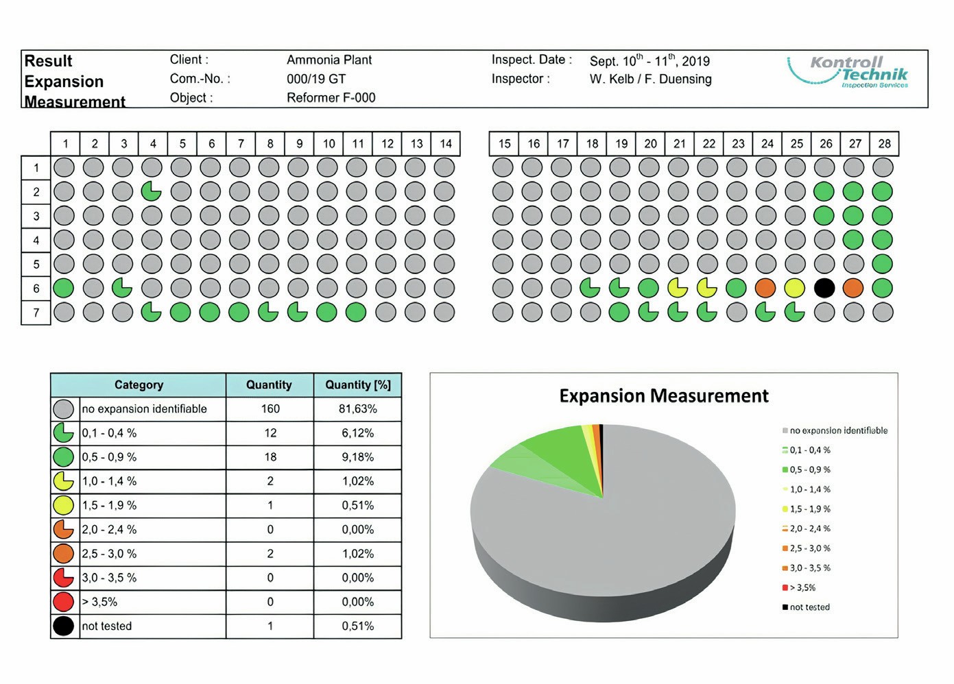
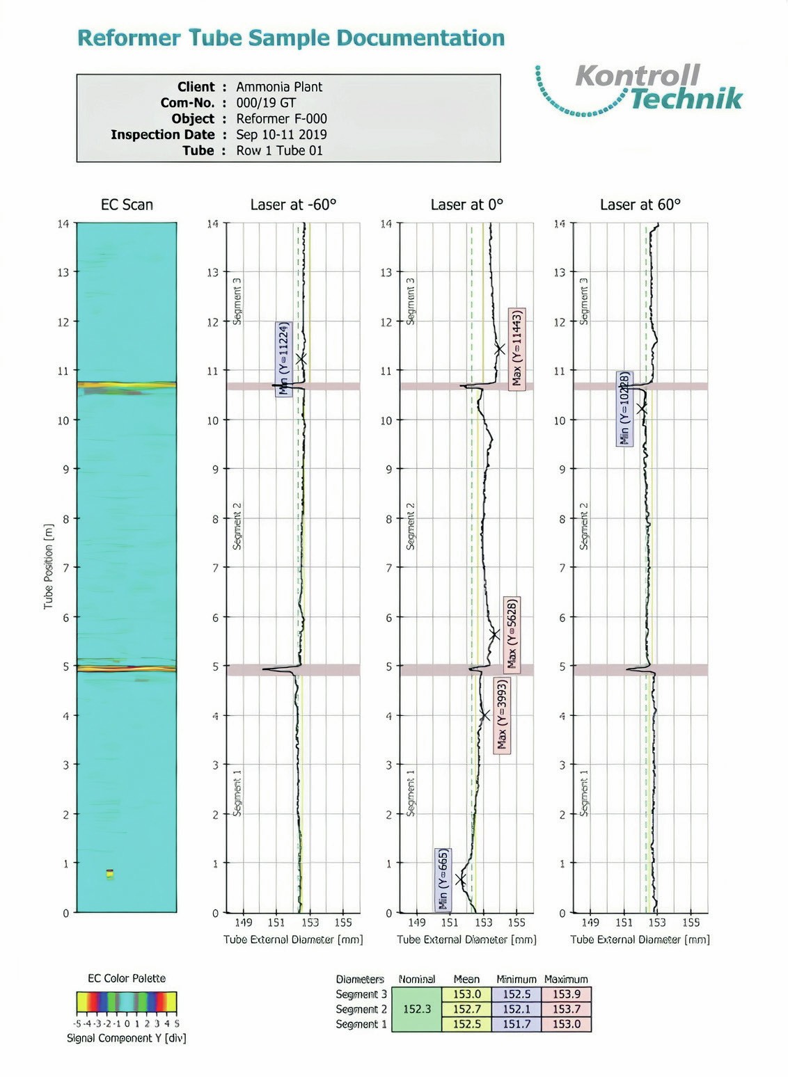
After the inspection the recorded data is analysed, and a report is generated to present to the client during the close out meeting. In the report overviews are presented for both the expansion measurements and the eddy current crack detection results (Fig. 4).
Result documentation
EC-testing
- eddy current result presentation in colour scan mode for the entire tube circumference;
- easy identification of defects.
Laser testing
- evaluation of minimum, maximum and mean diameter for each tube section at the whole circumference (internal reformer tube testing);
- evaluation of minimum, maximum and mean diameter for each tube section at three circumferential positions (external reformer tube testing);
- comparison of maximum diameter to nominal and/or mean diameter for each tube section;
- comparison of data with previous or fingerprint laser testing data.
Conclusion
With the advancements in reformer tube metallurgy and catalyst life the time between shutdowns is being increased, increasing the importance of technology to monitor reformer health.
Combining online reformer surveys and inspection data obtained during shutdowns helps to give a complete overview of reformer health, allowing plant management to make better informed decisions on operation and maintenance moving forward.
BD ENERGY SYSTEMS
SMR performance improvements for efficiency and safety
The steam methane reformer (SMR) is an energy intensive system and is the largest and most expensive equipment item in a conventional syngas plant. Many of the components of the SMR and the related heat recovery system require high grade materials to ensure safe and reliable operation in conjunction with a satisfactory operating life. Proper operation coupled with a good maintenance/inspection program will maximise the operating life of these components and increase the reliability and safe operation of the SMR as well. With the current focus on environmental emissions, proper operation will also minimise the greenhouse gas emissions through the stack via more efficient operation. A large number of studies and projects have been conducted by BD Energy Systems (BDES) personnel to improve the operation, reliability, and safe operation of steam-methane reformers. The following is a summary of areas that should be considered in operating and maintaining the SMR and related equipment to increase reliability, reduce downtime, and reduce emissions.
Mechanical
Hot/cold balancing
Before a multi-row reformer is commissioned after replacing the catalyst tubes, a cold radiant coil balance is performed to ensure that the weight of the system is properly and evenly supported to reduce stresses before the furnace is placed into service. After the reformer is in operation at stable conditions, a hot balance is performed to again ensure that weight is evenly supported in the hot condition and the stresses on the catalyst tubes, risers, and outlet manifolds are minimised. These balances are critical to overall radiant coil health and longevity of these components.
Inlet/outlet system stress analysis
A thorough stress analysis of both the inlet feed piping system to the catalyst tubes as well as an analysis of the catalyst tube effluent piping system is recommended. BDES has seen several outlet support systems that did not perform well after re-tubing, even though the change in mass of the tubes and catalyst was marginal. Fig. 1 is a representative illustration of an inlet/outlet systems that includes the catalyst tubes and associated supports.
SMR process and mechanical evaluation
This evaluation is a survey of the reformer furnace and its associated equipment that addresses the current level of instrumentation, control methods, and mechanical features and compares them with different recommended levels with explanations given for the recommendations. It includes discussions with plant personnel to address any specific concerns regarding design and operations. This study begins with a field survey of the reformer and its equipment and review of the current mechanical drawings and addresses:
- recommended minimum instrumentation required for efficient operation;
- recommended instrumentation to allow optimised operation more completely;
- recommended SOPs and operator instruction regarding what to observe while on their shifts;
- a field survey will be conducted on each reformer noting missing instrumentation, potential mechanical issues or observed anomalies, discussions with operations concerning current operating practices vs general industry standards;
- recommended minimum instrumentation required for efficient operation;
- mechanically related recommendations (if any) for increased reliability.
Design deficiencies
SMRs are utilised for the production of syngas for various end products such as ammonia, hydrogen, methanol, and reducing gas. Each of these processes vary in intensity with regards to pressure and temperature and as such, each process requires design margins and considerations to far exceed those recommended in API-560 and API-530. These margins affect:
- outlet systems;
- convection sections;
- high temperature components;
- equipment design margin issues.
Personnel and safety
SMR training
BDES has assembled a comprehensive curriculum on reformer furnaces that includes topics on reaction kinetics, operations, and mechanical design. BDES offers this training on-site or at its main office in Houston, Texas over a three-day period. This course is designed for plant personnel in all disciplines to attend whether it’s maintenance, operations, or engineering.
Operator Training
On site operator training is available and can be tailored for any specific topics that the client requests or to target specific problem areas. The training can be designed to provide training such that all shifts are trained. Some representative training topics that have been presented are: l burner balancing; l operator rounds; l understanding heat transfer.
Tube growth monitor (TGM)
TGM is a permanently installed method for monitoring catalyst tube temperature and provides for a practically immediate response mechanism to alarm of tube overheating and imminent tube failure.
Process analysis
SMR studies
This study is a comprehensive analysis of the reformer system and includes (if present) the reformer, convection coils, auxiliary boiler, air preheater, FD and ID fans, and associated drivers. This study includes an analysis of radiant section efficiency, calculation of the tube metal temperatures, calculation of the temperature margins of all tubes and coils based on current operating conditions, efficiency of the convection coils, pressure drops, flame patterns, FD/ID fans, and specific conclusions and recommendations regarding any areas of concern or actions that need to be taken.
The study results can also be utilised to assess the reformer and associated equipment for increased production, reduced energy consumption. or other different operating scenarios.
“Catalyst tubes in the areas with higher TMTs will have a shorter tube life.”
Furnace balancing
Furnace balancing involves balancing the heat distribution throughout the radiant and convection sections of the reformer. The maldistribution of heat in the radiant section can lead to several operating and mechanical problems such as inconsistent process outlet temperatures (for multi-row reformers) and inconsistent catalyst tube metal temperatures (TMTs). There can be several factors that affect the heat distribution including deficiencies in the existing combustion air and/or fuel gas flow control and distribution systems that must be addressed in order to carry out a proper balancing of air and fuel to the burners.
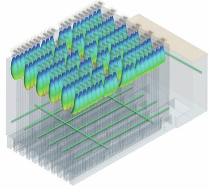
CFD modelling
CFD modelling may be used in studying an unbalanced furnace, but it is also useful in many other applications. CFD analysis can be utilised anywhere in the reformer from the air preheat system all the way through to the stack. Areas of analysis include: l heat transfer and heating uniformity; l study the effectiveness of mixing elements used for NOx control; l assess burner flame and flue gas flow patterns (Fig. 2); l assess combustion air flow patterns; l burner compatibility with reformer design (Fig. 2).
Tramp air study
Tramp air is any atmospheric air that enters the flue gas stream without passing through the burner. The effect of tramp air is a reduction in overall reformer efficiency due to the fact that heat from the flue gas is wasted by heating the atmospheric air instead of heating the catalyst tubes and/or the convection coils. A further decrease in efficiency occurs because the ID Fan must remove this excess air requiring more energy to do so and decreases real fan capacity. In some cases, the tramp air can have a very large effect on efficiency while also imposing a limit on plant capacity.
A tramp air study will quantify the amount of air infiltration into the reformer system and identify the sources of tramp air access into the reformer. Recommendations of corrective measures that can be taken are also advised.
Flue gas tunnel study
The flue gas tunnels, or coffins, have a necessary function in the design of a downfired reformer furnace. A properly designed tunnel will remove flue gas from the radiant section in a uniform manner such that all flue gas flow is evenly distributed over the length of the tunnel and radiant coil. A tunnel that is not properly designed or is operating far above its original design capacity will cause a maldistribution of flue gas flow patterns which in turn can result in a maldistribution of heat transfer to the catalyst tubes. This type of operation can cause areas where the catalyst tube TMTs are lower than average and some areas where the TMTs are higher than average. Studies have shown that the catalyst tubes in the areas with higher TMTs will have a shorter tube life and may fail prematurely.
A tunnel study will assess the current design of the tunnels based on current and/or future operating rates. This assessment will be compared to recommended changes to the tunnels to alleviate the maldistribution and limitations will be stated with regards to the current tunnel design.
A comparison will also be made to a TOP™ (Tunnel Optimal Performance) designed tunnel utilising new tunnel design software and materials by BDES. These tunnels have been developed and designed to allow near-perfect even flow into the tunnels with superior structural stability.
Figs 3 and 4 are illustrations of the CFD analysis of a conventionally designed tunnel compared to a TOP™ designed tunnel for the same SMR.
Summary
The proper operation and maintenance of a steam-methane reformer will increase the reliability and safety of the unit. Scheduled turnarounds for upgrades, repairs, and component replacement are a critical aspect of maintaining the overall health and longevity of an SMR and its associated equipment items. But just as important are regularly scheduled studies and analyses that are performed while the unit is operating which can reveal operating problems or drifts away from good operating practice before they become major issues. Having regularly scheduled maintenance activities and studies will enable the SMR to operate at its best and safest potential.
ONPOINT — A KOCH ENGINEERED SOLUTIONS COMPANY
Stay in the loop — new capabilities to optimise steam methane reformers
As reformer operation moves into the automated future, there remains a gap in real-time, detailed information about the combustion process within the heater. Increasing visibility of key parameters in locations within the firebox, combined with real-time quantitative insights about the health and operation of the heater, can enable operations to make simultaneous improvements of emissions, safety, reliability, and profitability and move control of the asset away from manual, inspection-based manipulations and into the future of automated control.
Steam methane reformers have many critical parameters. Optimising these systems beyond a base-case can be especially challenging. Optimisation efforts often focus on a single area of interest, and the steps taken can result in subsequent issues that negatively impact safety and reliability. Many combustion-related safety and reliability issues can be difficult to observe directly, and they often increase in severity over time.
Technologies are now available to cost-effectively monitor and automate large industrial heaters. Traditionally, these heaters have relied on a handful of point sensors to represent a multitude of combustion and process control parameters, typically at the global level. While this is generally sufficient for small heaters, the lack of available data for larger heaters with many zones of combustion results in blind spots of furnace operation. Measurements from single sensors are often falsely assumed to represent all the combustion products in the heater. Alternatively, new monitoring technologies, such as the ZoloSCAN ™ system, exist which can economically detect total products of combustion at multiple locations to help remove the uncertainty from limited downstream sensors and correct common combustion-related problems.
Steam methane reformers
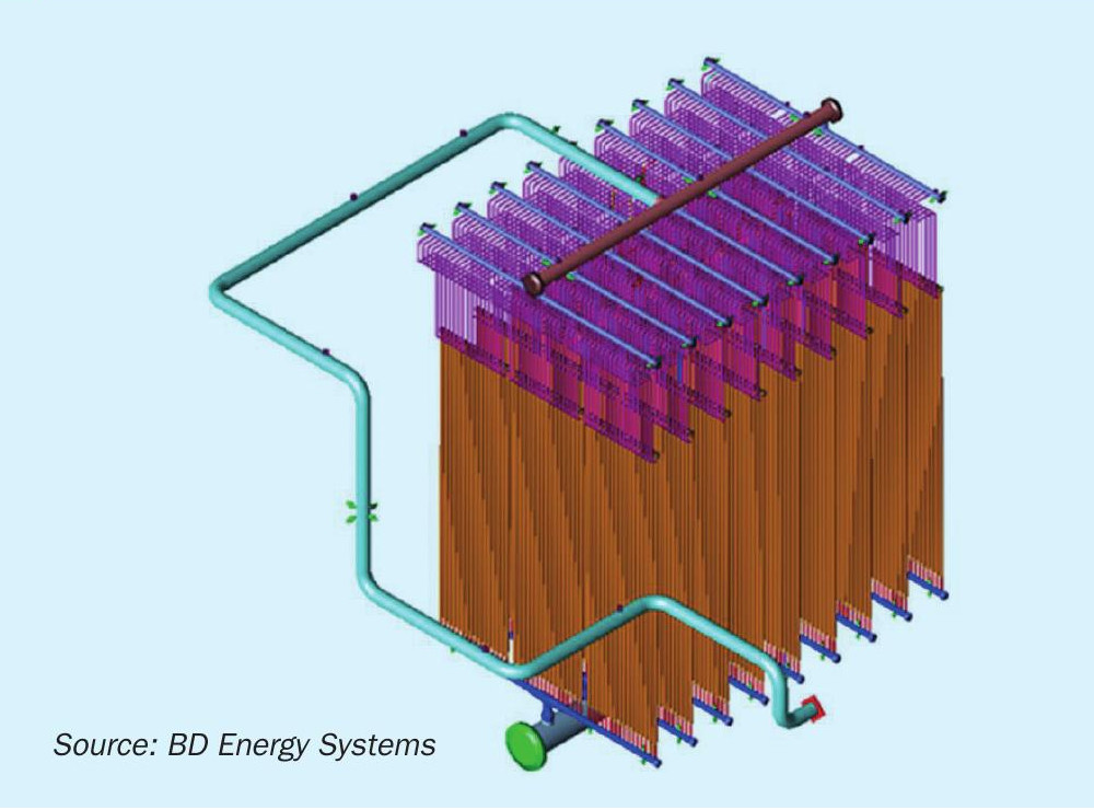
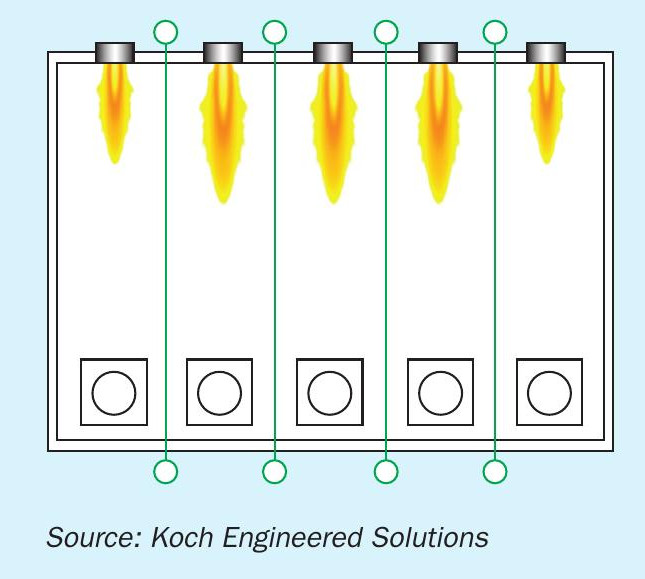
Steam methane reformers historically are large heaters with many burners, commonly over 100, installed in the roof of the heater and down fired (see Fig. 1). It is typical for these systems to be operated with both a forced and an induced draft fan (balanced draft system) and preheated combustion air for improved efficiency and control. The burners are installed in multiple lanes, or rows, with process tubes located between each burner lane. This is illustrated in Fig. 2 with the rows of process tubes identified as the green lines. The burners in the outer lanes, left and right side of Fig. 2, are typically designed to fire between 50-65% of the heat release of the inner lane burners.
As burner technology has changed over the last several decades from pre-mix or conventional raw-gas burners to ultra-low NOx, the basic design of reformers has stayed the same. To meet more stringent emissions requirements, the changes in burner design have resulted in longer flame lengths that are more susceptible to adverse internal flue gas recirculation patterns within the heater.
Common issues
There are several common issues observed in steam methane reformers. Many of these issues are related and cause compounded issues such as decreased efficiency, flame impingement, and localised hotspots on tubes that cause decreased tube life and limited production rates.
Perhaps one of the most common issues found in combustion systems is the maldistribution of the combustion air delivered to the burners 1 . Combustion air maldistribution results in variation of the air-to-fuel ratio for each burner. In some forced draft systems, these air-to-fuel ratio imbalances can be observed from one row of burners to the next, as well as down the length of each burner row. The impact of varying air-to-fuel ratios per burner can result in some burners operating below the stoichiometric limit causing large flames and increased CO emissions levels. Other burners operating with too much excess air can result in increased NOx emissions.
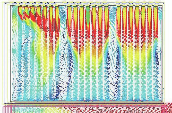
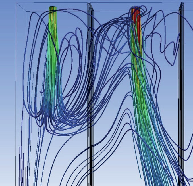
Another common issue found in combustion systems is adverse flue gas patterns. Unproportioned burner momentum per available firebox area often results in flue gas patterns which cause the flames from the outer lanes to be pulled through or across the process tubes to adjacent inner lanes. Ultra-low NOx burners tend to exacerbate this problem due to their longer flame lengths. In Fig. 3, the flue gas is represented using particle streamlines in a CFD modelling simulation of a steam methane reformer. Momentum is illustrated by colour with the scale transitioning from high momentum (red streamlines) to lower momentum (blue streamlines). The higher momentum of the inner lane flue gas (right side of figure) draws the flue gas from the outer lane through the process tubes near the roof of the reformer. In many cases, adverse flue gas patterns create undesirable hot spots on the process tubes. Prolonged hot spots can lead to tube failure.
Optimisation and outcomes
One typical operational target for a combustion system is to reduce the global excess oxygen (O2 ) to increase efficiency. When optimising for a low global excess O2 level without knowledge of individual burner or O2 distributions, an operator could unknowingly create a situation where burners have sub-stoichiometric combustion. This can result in an increase in burner flame lengths and potential impingement on process tubes, unburned fuel being drawn into a different zone of the reformer before combusting, and ultimately reduced efficiency of the reformer due to improper heat distribution on the process tubes.
ZoloSCAN laser grid
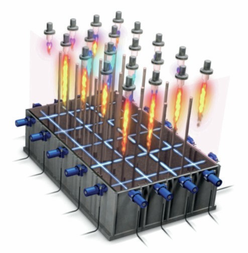
To the adage, “you can’t improve what you can’t measure,” combustion monitoring tools are now available to quantify products of combustion directly within the firebox. The new technologies address a root cause of many of the issues reviewed above, specifically undiagnosed local variations in combustion. Most notably, the ZoloSCAN combustion monitor utilises tunable diode laser absorption spectroscopy (TDLAS) technology to simultaneously measure temperature, O2 , CO, CH4 and H2 O in real-time, directly in a reformer (see Fig. 4) or large process heater, along multiple laser paths. Measurements can be used to provide a more accurate and representative quantification of combustion gases in a furnace vs. traditional, single-point thermocouples or ZrO2 sensors. This is possible by orienting laser paths below reformer burner rows to provide path average measurements of each burner row in the firebox. This information can then be used to make control improvements of fuel and air distributions.
While each combustion monitoring system is unique, the ZoloSCAN system operates by simultaneously transmitting multiple laser wavelengths for multiple constituents measured on each laser path. The result is a path-average value for each constituent for that path. The paths are monitored sequentially, with all constituents measured first on path one, then on path two, until all the paths have been measured, typically in less than two minutes total time. The sequence then starts over again.
In-furnace combustion data benefits operators and process engineers by reducing the need to run at higher than desired excess oxygen setpoints. Reduced excess oxygen results in reduced fuel consumption, the potential to increase production, or a combination of both. Assets utilising the ZoloSCAN system commonly control excess oxygen in the range of 1.5 to 2.0% across the heater while simultaneously maintaining minimal CO2 . This compares to traditional heaters that usually run above 4% excess O2 . Additionally, TDLAS temperature measurements allow for improved heat distribution across the firebox, thereby reducing tube metal temperature deviations. The temperature profiles may be optimised for uniform heat flux to allow for increased capacity and increased tube life via the reduction of temperature hot spots3 .
Sensor to solution
Ultimately a sensor alone will not result in reformer process improvements. For the best effect, ZoloSCAN data, or any monitoring system, needs to be integrated into an advisory or automated process control loop to result in a meaningful and sustained operational solution. For deployments on steam methane reformers, this control loop often comes in the form of an advanced process control (APC) package for closed loop control or OnPoint’s Ember™ software for open loop control.
Either option is relatively straight forward from a control perspective. For APC, data from the ZoloSCAN system is continuously transferred via OPC or Modbus to the plant’s historian. Once integrated, often the visibility of combustion data allows for new tuning and maintenance evaluations not previously possible. With an initial tuning of the heater, target operation of the heater can often be sustained with more simple control loops, like fan damper biasing, biased O2 and CO distributions within the firebox4 . Each reformer is unique and integration plans may vary. For open loop combustion control, Ember outputs direct air register recommended setpoints which can be applied in the field by operators or engineers to optimise combustion for reduced global O2 and improved temperature and oxygen distribution.
Conclusion
The tools for local or zonal quantification of in-furnace combustion now exist. While not as necessary for small heaters, laser grid-based combustion monitoring technologies fill a critical gap in large reformers where aggregate downstream measurements can only represent the entirety of the heater combustion and give no indication of the local variations. Augmenting existing sensors with distributed combustion feedback inside the firebox, coupled with simple control strategies, can result in sustained, efficient, and productive operation of a reformer.
References
QUEST INTEGRITY
Reformer tube management: combining life assessment and diagnosis of operational issues
For any plant that counts a steam reformer among its assets, plant reliability is invariably linked to management of the reformer catalyst tubes. The output of the reformer is often a key determining factor for downstream production rates, so a single catalyst tube failure can bring an entire plant down for a week or more and have an economic impact in the millions of dollars. In the reformer furnace environment, the primary threat to catalyst tube integrity is progressive creep damage. The rate of damage accumulation is determined by the reformer operating conditions. An accurate tube condition assessment and remaining life prediction methodology that can also aid in identifying operational issues can therefore play a significant role in overall plant reliability. The LifeQuest Reformer™ methodology and software package developed by Quest Integrity uses a unique approach to life assessment that fulfils both of these criteria.
LifeQuest Reformer
LifeQuest Reformer was born from the inability to accurately predict catalyst tube service lifetimes using conventional creep life assessment methods such as the Omega method or the Larson-Miller approach. The general methodology is consistent with the requirements for an API 579-1/ASME FFS-1 Fitness-for-Service Level 3 assessment1 , but there are two key aspects that make LifeQuest Reformer unique.
First, it was recognised that the typical approach of using constant material property values in creep life assessments was not valid for the HP alloys widely used for catalyst tubes. It is known that during exposure to service temperatures, the microstructure of HP alloys changes considerably due to aging. This in turn decreases creep strength over time2 . LifeQuest Reformer captures this effect through a dynamic creep model that accounts for the thermal exposure of the material and the resultant aging effect. This model was developed from a proprietary creep test database created by Quest Integrity for aged and as-cast catalyst tube materials and has been validated through both laboratory testing and in-service assessment of well over 100,000 individual catalyst tubes.
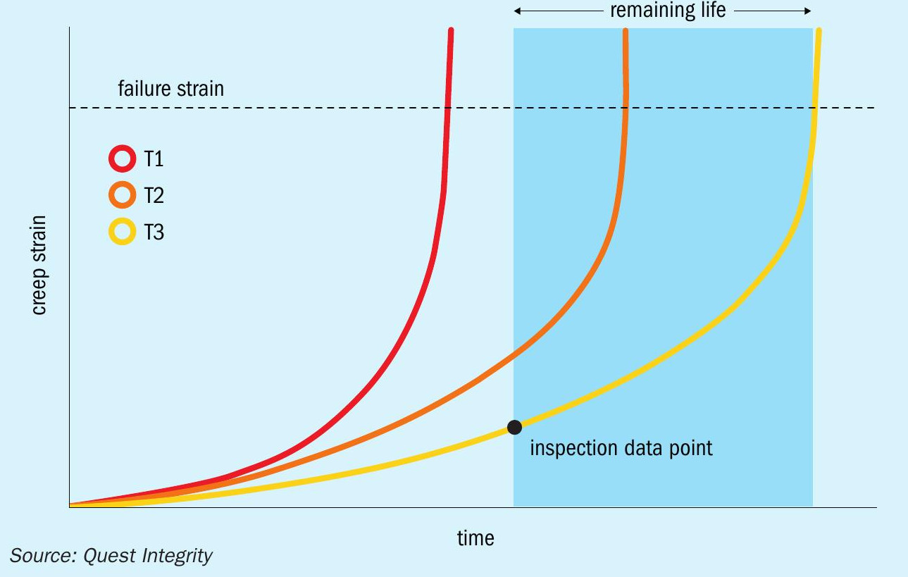
Second, LifeQuest Reformer removes the conventional creep life assessment requirement for temperature data as an input. Accurate measurement of tube metal temperature (TMT) in a reformer furnace is inherently difficult and typically has large associated uncertainties that can lead to variations of -75% to +300% in remaining life calculations3 . However, given an accurate material creep property model and a known stress, a unique strain-time curve can be generated for any chosen temperature. If creep strain is measured at a known time, the unique curve that passes through that data point can be identified and the “effective” TMT determined. This is the temperature that would produce an equivalent amount of strain over the time period considered. Remaining life is then calculated by extrapolating the strain-time curve to the failure point. An illustration of this methodology is provided in Fig. 1. Multiple data points and changes in operating conditions can also be accommodated by stitching together a sequence of partial strain-time curves.
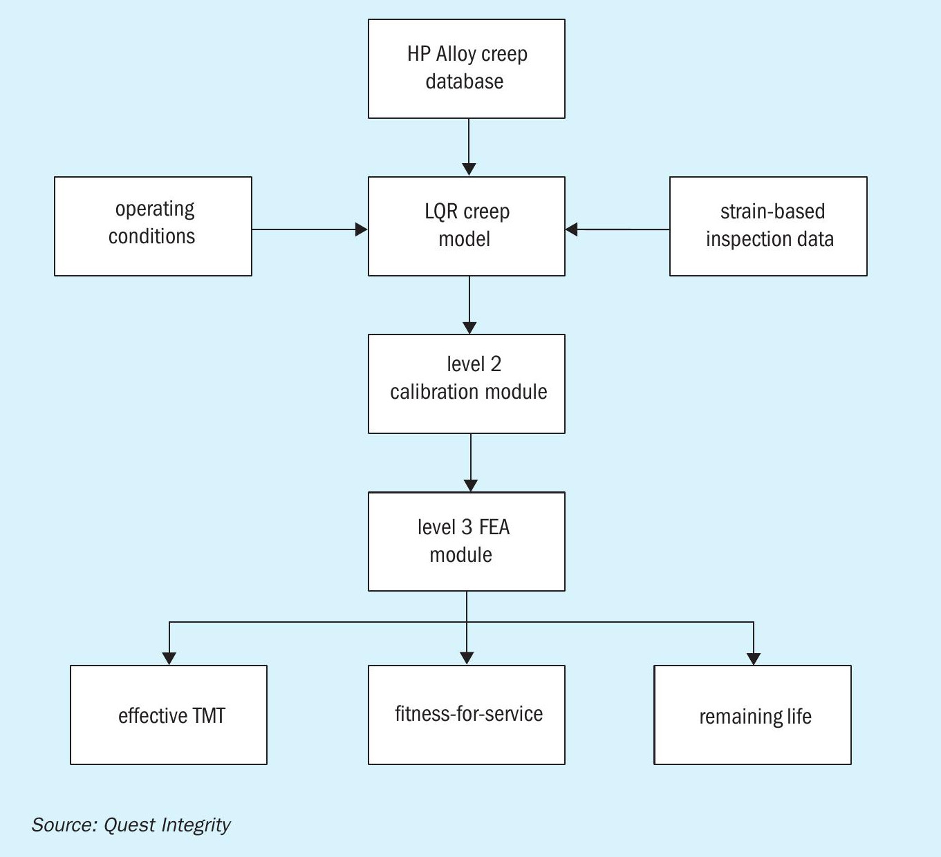
The full LifeQuest Reformer methodology and assessment outputs are summarised in Fig. 2. Any diametric inspection data can be used as an input, provided a pre-service baseline diameter has been measured or can be estimated. Quest Integrity has also developed a Rapid Assessment version equivalent to an API 579-1 Level 2 assessment that can be used during plant turnarounds to provide tube replacement plans within 24 to 48 hours of inspection. The Rapid Assessment is typically undertaken when it is anticipated that tube replacements will be required during the turnaround, but the tubes to be replaced need to be verified or there is no prior assessment identifying these tubes. The full Level 3 assessment then provides a more detailed analysis of inspection and operating data, operating risk and uncertainties, replacement planning for future turnarounds, and recommendations for future operation including TMT operating limits.
Case study: Diagnosis of operational issues
Another notable advantage of the LifeQuest Reformer methodology is that it can identify reformer operational issues. A series of inspections and assessments undertaken by Quest Integrity on a reformer furnace illustrates this valuable feature.
The reformer in question contained 64 catalyst tubes and had a history of tube failures and temperature issues. The key events over the 11-year period from tube commissioning to the most recent inspection are summarised as follows:
In Year 3 of operation, three tube ruptures occurred during a start-up. Significant abnormal creep damage was also identified in the majority of tubes. Replacement of the failed tubes was scheduled for the next available opportunity in Year 5, and one additional tube was removed from service due to the risk of failure prior to Year 5.
In Year 5, 23 tubes were replaced after being predicted to reach the damage threshold for retirement before the next tube replacement opportunity in Year 11.
In Year 8, hotspots consistent with catalyst deactivation were observed on multiple tubes, and temperatures well above design were recorded over a period of several days. The catalyst in all tubes was replaced, which resolved the issue.Five tubes were removed from service after being identified as being at high risk of failure due to creep damage before the Year 11 turnaround.
In Year 11, three more tubes ruptured during a start-up. Again, significant levels of abnormal creep damage were widespread throughout the reformer. Thirteen tubes were replaced, and a further eight removed from service due to the predicted failure risk and a lack of sufficient spare tubes.
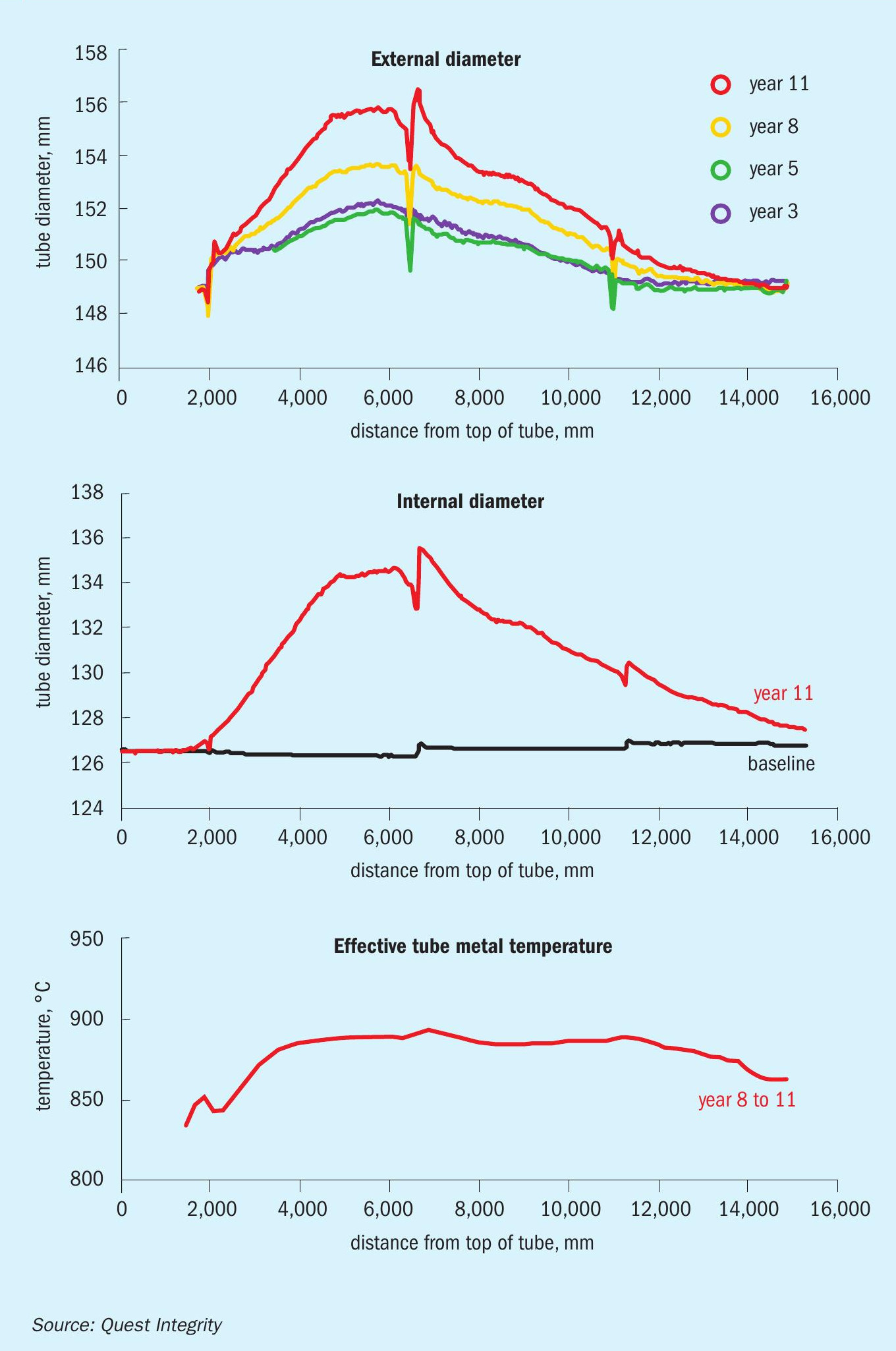
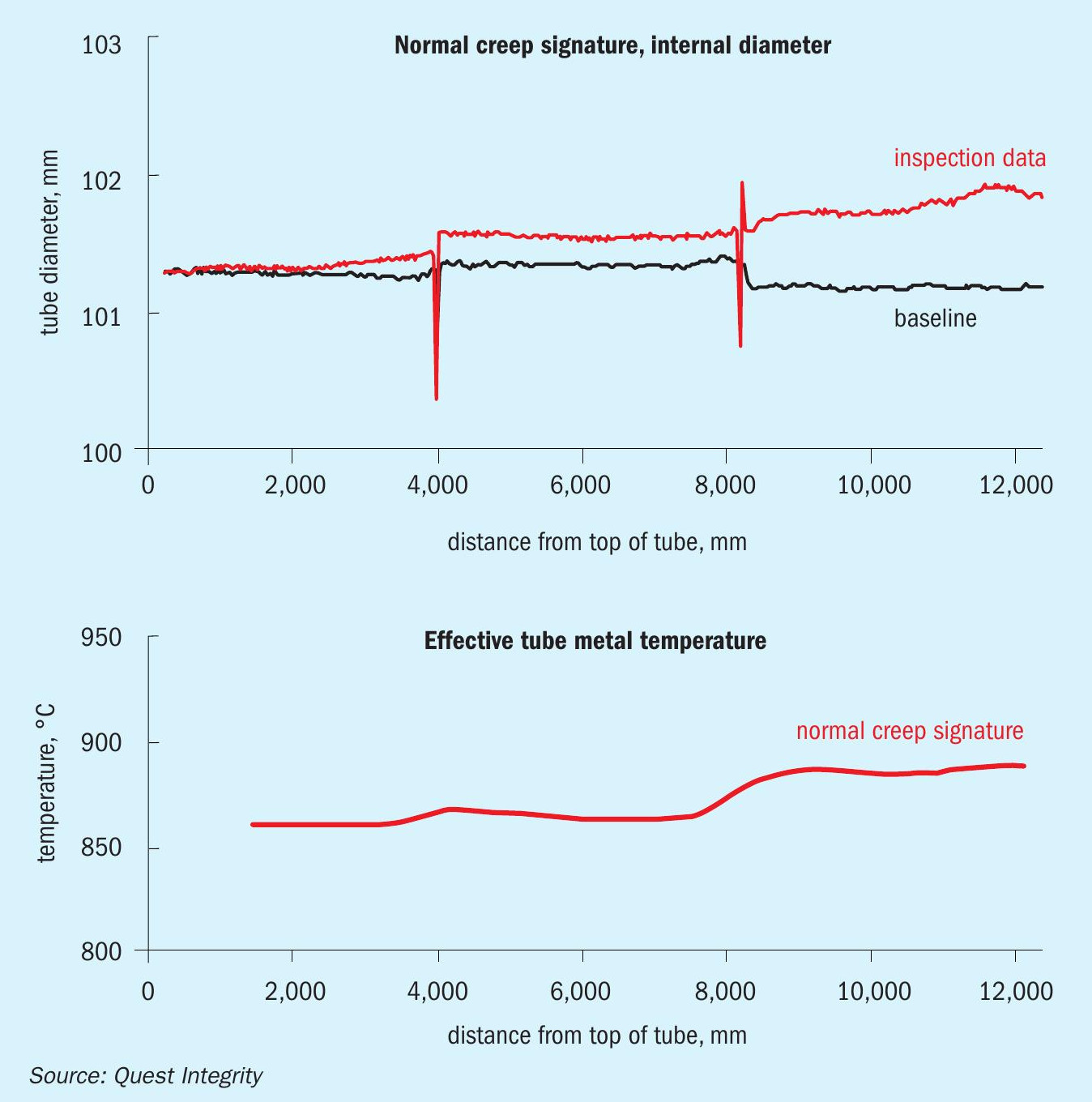
External diametric inspections of all tubes were carried out in Year 3, Year 5, Year 8, and Year 11. Internal diameter data was recorded for all tubes before entering service, and again in the Year 11 turnaround. Examples of diameter profiles from all inspections are shown in Fig. 3. The corresponding calibrated effective TMT profile for the Year 8 to Year 11 period is also shown. Similar profiles were calculated for the period prior to Year 3 and the Year 5 to Year 8 period. For reference, a “normal” catalyst tube creep signature and calibrated effective temperature profile from another reformer is shown in Fig. 4.
The diameter and temperature profiles in Fig. 3 illustrate trends consistently observed throughout this reformer: abnormally high levels of creep damage in the upper catalyst tube sections in all operating periods except Year 3 to Year 5, and corresponding high effective temperatures in the same locations (relative to the expected “normal” profile represented by Fig. 4). The hotspots observed in Year 8 offered a feasible explanation for the creep damage recorded in the Year 5 to Year 8 period, but no such issues were identified in the period prior to Year 3 or the Year 8 to Year 11 period. Regular online monitoring of TMTs also indicated that tube temperature profiles throughout these periods were generally consistent with a “normal” profile similar to that shown in Fig. 4.
This latter point was a key indicator that the issues causing the abnormal creep damage in these two periods actually lay outside normal operation in the reformer start-up procedure. The mismatch between the effective and measured TMTs suggested that there had been one or more events outside of the monitoring windows where the upper sections of the tubes had overheated, but then returned to normal operating temperatures. The start-up sequence was the only point in operation where this could feasibly have occurred. In this reformer, TMTs were not monitored during transients such as start-up so there were no obvious indicators that might have alerted operators to any issues. Further evidence to support this conclusion was provided by the tube failures themselves: both the Year 3 and Year 11 failures had occurred in the top third of the tubes where any overheating effect during start-up would have been most potent, the appearance of the failures was characteristic of short-term overheat, and all had occurred during the start-up sequence.
The lack of creep damage accumulated in the Year 3 to Year 5 period indicated that the overheating issues prior to Year 3 had been resolved. However, this was evidently temporary as shown by the later re-surfacing of the problem. This prompted a root cause analysis of the tube failures in Year 11, which unearthed a number of red flags in the operational data from past start-ups. From this, Quest Integrity was able to provide recommendations on targeted actions to reduce the likelihood of future overheating events.
Concluding remarks
This case study illustrates how the Life-Quest Reformer methodology can play a critical role in providing insight into reformer operational issues. The combination of this diagnostic capability with a technically sound and proven life assessment approach has significant benefits for catalyst tube integrity management. Ultimately, these benefits feed down into improved overall plant reliability. The costs of a high-quality tube inspection and assessment program are not negligible, but they are still small in comparison to those incurred by an unscheduled plant shutdown. Consequently, there is little justification for failing to make use of the operational advantages afforded by tools such as LifeQuest Reformer.
References