Sulphur 399 Mar-Apr 2022

31 March 2022
Sulphuric acid plant integration in a chemical complex
SULPHURIC ACID TECHNOLOGY
Sulphuric acid plant integration in a chemical complex
A sulphuric acid plant forms critical material and energy interfaces with other plants in several different types of chemical and metallurgical complexes. Shailesh Sampat of SNC-Lavalin discusses how the acid plant design is customised to match the product mix and the energy requirements of the complex to provide the optimum solution for energy and material requirements.
Although the principal function of the sulphuric acid plant is to produce sulphur-based compounds using sulphur or sulphur dioxide (SO2 ) as raw material, it also serves as a critical source of energy for the complex. Heat generated due to the combustion of sulphur, conversion of SO2 to sulphur trioxide (SO3 ) and formation of sulphuric acid are all significant offering value in terms of energy which is comparable to the value of production of sulphuric acid and other chemicals for the associated site processes. Sulphuric acid plants operate with a zero or negative carbon footprint, as all the power required to run the complex can be generated within the complex with the possibility to export power. This essentially reduces the carbon footprint of the entire complex.
It is not surprising therefore that the sulphuric acid plant is a critical part of several different types of chemical and metallurgical complexes. In fact, many chemical/metallurgical complexes are designed and built around a sulphuric acid plant. This article provides an insight into the configurations of several types of chemical complexes that are integrated around the sulphuric acid plant. These include:
- phosphatic fertilizer complex (diammonium phosphate, single super phosphate, phosphoric acid);
- pyrometallurgical complex (copper smelter, zinc roaster);
- hydrometallurgical complex (copper, nickel, cobalt leach);
- detergent/dyestuffs (linear alkyl benzene, lauryl alcohol, alpha olefins).
SNC-Lavalin has experience in building numerous types of complexes around sulphuric acid plants. This has led to a deep understanding of licensor’s technology as well as requirements of different types of industrial complexes. Developing a good match between the two is the main role of an engineering contractor.
While designing such complexes, one needs to understand the interfaces between the sulphuric acid plant and the remainder of the complex.
There are two types of interfaces between a sulphuric acid plant and the rest of the complex:
- Material interfaces: These are interfaces consisting of raw materials and final products from the plant. In the case of metallurgical gas plants, SO2 – bearing gas streams from a smelter or roaster forms an important interface.
- Energy interfaces: These are energy streams which can be in form of low-pressure/high-pressure steam, electric power, hot air or hot water.
Some of the interfaces have intermediate buffers in terms of storage tanks and vents or drains that allow short term delinking of each area or each plant from one another, to allow independent operation. In many cases there is no buffer capacity in between plants in the complex and changes at one end immediately impact the operation at the other end. So, taking stock of the upstream and downstream plant capacity requirements for receiving the sulphur-based gas, and producing sulphur products for leaching etc., accounting for each end of the sulphuric acid plant, becomes the first design requirement in any sulphuric acid plant process design. Defining the operating factor, availability and utilisation of each plant is an essential first step in the process design.
SNC-Lavalin has extensive experience in customising sulphuric acid plants for phosphatic fertilizer complex, hydro-metallurgical plants producing copper/nickel/ cobalt, and pyro-metallurgical plants such as copper smelters and zinc roasters.
Sulphuric acid plants produce a number of important sulphur compounds:
- 93-98.5% sulphuric acid: Used for producing phosphatic fertilizers such as phosphoric acid and single superphosphate from rock phosphate in a fertilizer complex. Also used for leaching copper/nickel/cobalt from the ore in a hydro-metallurgical plant.
- Oleum with 25%-65% free SO3 : Used as a sulphonation agent in complexes producing detergent, dyestuffs, and pharmaceutical intermediates.
- SO3 pure liquefied: Used as a gas phase sulphonation agent within the complex or transported for use in other locations.
- SO2 gas stream of various concentrations: Used as a reactant in hydrometallurgical copper plants, caprolactam plants, cyanide destruction in mining operations and for bleaching in paper production.
Due to the exothermic nature of the reactions, a sulphuric acid plant is a major source of energy and often provides a large fraction of the energy requirements in the complex. This energy can be in different forms as described below:
- High-pressure (HP) steam 40-60 barg 400-500°C: Produced in economisers, boilers and superheaters using heat of combustion of sulphur and heat of conversion of SO2 to SO3 . Generally used for generating electrical power in a turbogenerator. Alternatively, it can also be used to drive large equipment such as main air compressors, boiler feed water pumps, etc.
- Intermediate-pressure (IP)/low-pressure (LP) steam at 6-11 barg pressure: Generated in the Heat Recovery System (HRS) of the absorbing acid circuit using heat of absorption of SO3 and formation of sulphuric acid. Alternatively, LP steam is extracted from the turbogenerator set that runs on HP steam feed. Used in sulphur section, phosphoric acid evaporators, desalination plants.
- Electrical power: HP steam is taken to a turbogenerator to generate electrical power for the entire complex. It often runs all of the major electrical drives in the complex and also exports power to the main grid.
- Hot air: Used in rotary dryers for granular fertilizers and spray dryers for detergents.
- Hot water: Saline water feed to desalination plant can be preheated to save energy. Warm water can be produced for cleaning gypsum cake from the phosphoric acid plant.
Phosphatic fertilizer complexes
A typical phosphatic fertilizer complex utilises 93-98.5% sulphuric acid to extract phosphate content from rock phosphate to produce phosphoric acid or lower-end fertilizers such as single superphosphate (SSP).
Energy recovery
Since the product mix does not include oleum, a plant designer can maximise energy recovery as HP steam from the gas circuit, generate IP/LP steam from the HRS in the acid circuit and in some cases, hot air for granulation plants. Generally, HP and IP steam produced in the sulphuric acid plant is taken to the turbogenerator set to generate electrical power. LP steam is extracted for use as required in the complex.
Energy requirements
Energy demands of a complex vary depending on the type of fertilizer being produced, the production capacity as well as the technology used. Typical phosphoric acid/ diammonium phosphate complexes use LP steam in phosphoric acid concentrators. The amount of LP steam requirement varies depending on concentration of the weak phosphoric acid produced in the complex which, in turn, depends on technology used for producing it (dihydrate, hemihydrate, hemi-dihydrate, etc.). Use of dihydrate technology produces phosphoric acid with a lower initial concentration and requires more steam in evaporators to concentrate it.
In some cases part of the high-level heat recovery comes in the form of hot air, which is used for granulation plants.
Saline water feed to the desalination plant is also preheated in some cases using energy available from the sulphuric acid plant.
Electrical power required to operate various plants
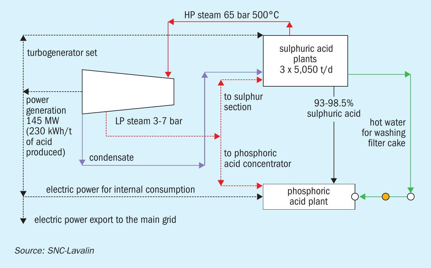
Typically, the capacity of the sulphuric acid plant is greater than 2,500 t/d for a phosphoric acid complex. For such large plants, the turbogenerator set for power generation and intermediate extraction of LP steam is economical. Steam generation at 60 barg gives a better return by higher power generation. At the same time, a significant amount of steam needs to be extracted from the turbine at ~7 and 3 barg for in-plant use in the sulphur section of the sulphuric acid plant and phosphoric acid plant evaporators. This limits the power generation in the turbogenerator set under normal operating scenarios.
Sulphuric acid plant capacities for a single superphosphate complex are smaller (100-200 t/d). In these plants, steam is utilised to drive major equipment such as the turbo-blower, boiler feed water and cooling water pumps.
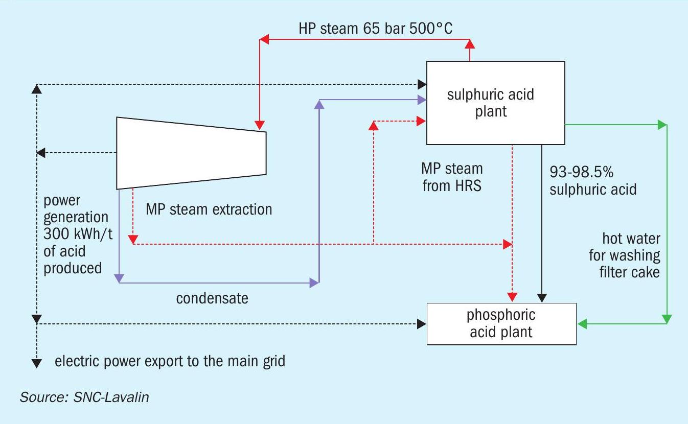
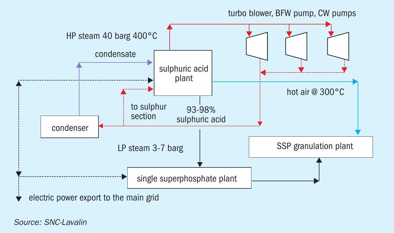
The material and energy block diagrams in Figs 1-3 show how the requirements of a phosphoric acid complex are matched with the energy recovery from a sulphuric acid plant in three different cases.
In the case of a sulphuric acid plant with no HRS in a small SSP fertilizer complex (Fig. 3) the steam generated in the sulphuric acid plant is used to drive large equipment such as turbo-blowers, BFW pumps, cooling water pumps etc. Due to the smaller size of plants, use of steam to drive large equipment is more economical compared to installing a condensing turbogenerator set.
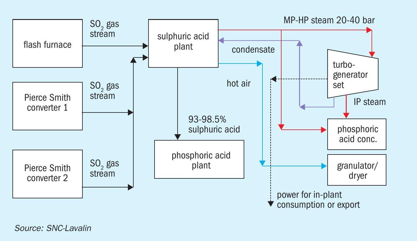
Pyrometallurgical complexes
Pyrometallurgical complexes consist of roasters/smelters that decompose sulphur-containing metal ores to produce metals such as copper and zinc. Sulphur present in the ore is converted to SO2 . SO2 -bearing gas streams from multiple sources (smelter/converter) are fed to the sulphuric acid plant to produce 93-98.5% sulphuric acid. These gas streams form important interfaces with the acid plant as it is necessary to maintain adequate suction at all the sources of SO2 as Pierce-Smith converters go through different operations (slag blow, copper blow etc.). Gas flows and suction pressures at sources should stabilise quickly after every such change to avoid SO2 gas leaking out into the working area.
Recent developments in metallurgical processes have resulted in gas streams containing higher SO2 concentrations. This not only allows autothermal operation of the sulphuric acid plant in DCDA mode but also allows heat recovery as MP/HP steam or hot air.
Sulphuric acid is essentially a by-product in these complexes. Sometimes a phosphatic fertilizer complex is built to utilise this acid. However, this is not always economical due to non-availability of rock phosphate at remote locations. Often sulphuric acid is sold off to consumers at throw away prices with no value addition for the plant operator. SNC-Lavalin also has access to technology to convert SO2 -bearing gas streams directly to sulphur.
Raw materials and products
In the case of a pyrometallurgical complex, the sulphuric acid plant has a material interface with the metallurgical plant in the form of the incoming SO2 gas stream. In addition to this, there will be other interfaces depending on how the sulphuric acid is utilised (refer to the earlier section on phosphatic fertilizer complexes).
Energy recovery
Excess heat in the system can be recovered as hot air in SO3 coolers or as steam in boilers. Boiler systems generally produce MP steam (£20 barg), however production of HP superheated steam at 40 barg is possible if high SO2 concentration is available on a consistent basis. Heat recovery from the acid circuit using HRS is also possible in such cases.
Energy requirements
Hot air or MP steam can be used in concentrate dryers at inlet of the smelter/ roaster. Hot air or MP steam can also be used in other locations in the complex such as phosphoric acid evaporators, granulator/dryers depending on how the sulphuric acid is utilised. If HP steam is generated, it can be utilised to drive equipment or generate electricity.
The material and energy block diagram in Fig. 4 shows how the requirements of the pyrometallurgical complex are matched with the energy recovery from the sulphuric acid plant.
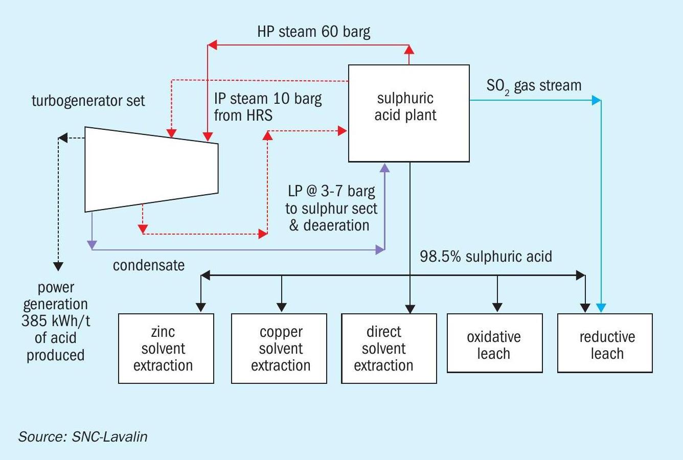
Hydrometallurgical complexes
Hydrometallurgical complexes use 93-98.5% sulphuric acid to leach the target metal ions such as copper, nickel or cobalt from the ore. At times, a gas stream containing 12% or more SO2 is also required to creating a reducing environment in the leached liquor.
Energy recovery
Since the product mix does not include oleum, the plant designer can maximise energy recovery as HP steam from the gas circuit and LP steam from the HRS in the acid circuit. Generally, the HP and IP steam produced in the sulphuric acid plant are taken to a turbogenerator set to generate electrical power. LP steam is extracted as required in the complex.
Energy requirements
All the steam is sent to a turbogenerator after meeting the internal requirement of the acid plant, as steam is not required as a heating media elsewhere.
The material and energy flow diagram in Fig. 5 shows how the requirements of the hydrometallurgical complex are matched with the energy recovery from the sulphuric acid plant.
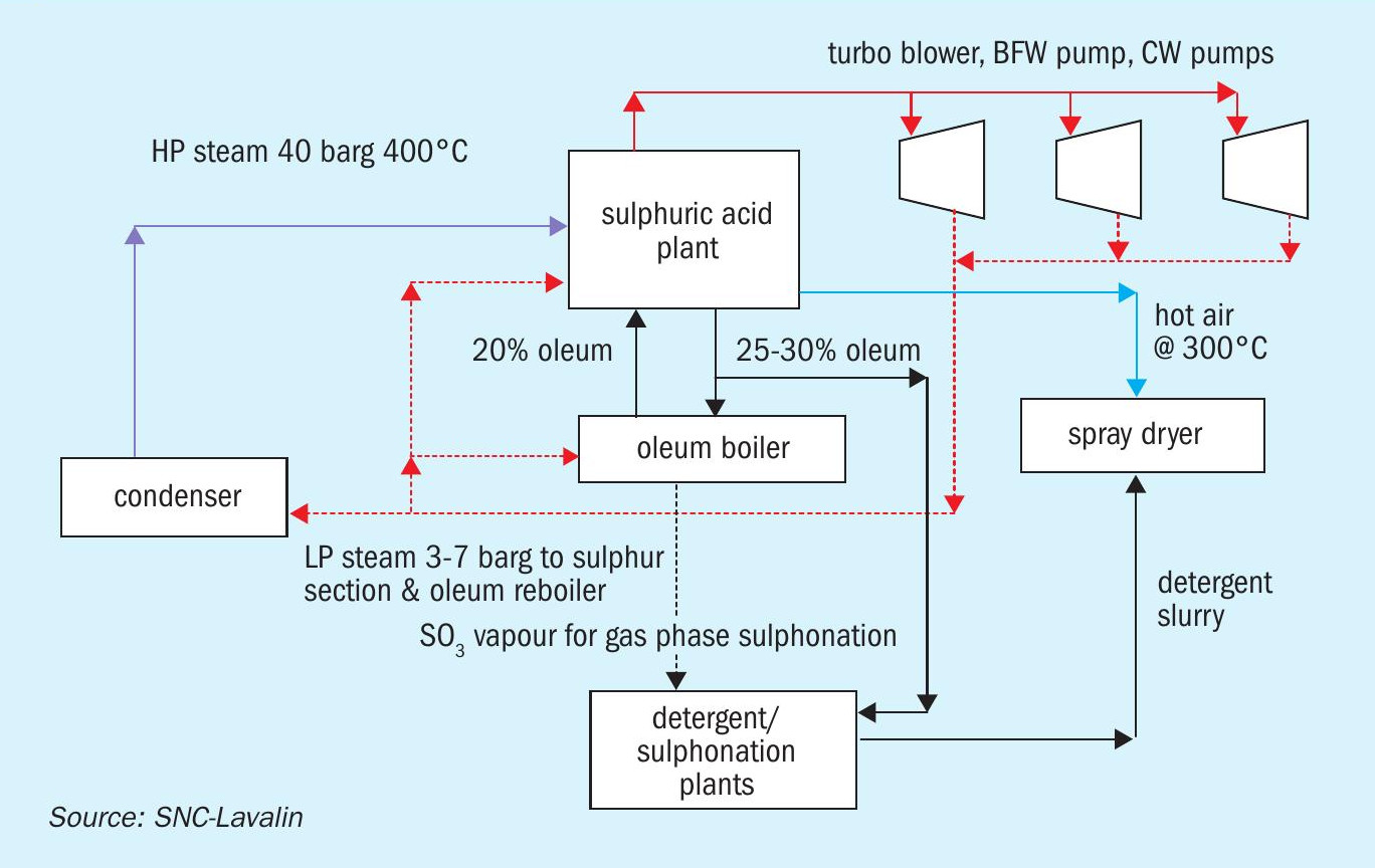
Detergent/dyes/sulphonation complexes
The main products from such complexes are formulations containing sulphonate of organic compounds such as linear alkyl benzene, lauryl alcohol, and alpha olefins. The sulphuric acid plant is the source of the sulphonating agents; oleum for liquid phase sulphonation and SO3 -containing gas stream for gas phase sulphonation. Plants are generally smaller in size compared to those in fertilizer complexes. In high humidity locations, the moisture balance in the plant may cause issues if production of high-strength oleum and SO3 gas need to be maximised. In such cases, part of the moisture from the air is removed by other drying methods like pre-cooling or silica gel dryers.
Energy recovery
Due to the presence of the oleum circuit, sulphuric acid plants in these complexes do not have an HRS based IP steam recovery from the acid circuit. The HP steam circuit is similar to the standard. Hot air generation is possible.
Energy requirements
Spray dryers in detergent plants and dyestuff plants require heat in the form of hot air.
Steam generated in the sulphuric acid plant is used to drive large equipment such as turbo-blowers, BFW pumps, cooling water pumps, and others. Due to the smaller size of the plants, the use of steam to drive major equipment is more economical compared to installing a condensing turbogenerator set, unless shortage of water forces the issue.
The material and energy block diagram in Fig. 6 shows how the requirements of the detergent complex are matched with the energy recovery from the sulphuric acid plant.
Engineering of interfaces for the complex
Each interface needs to be engineered carefully to ensure smooth and seamless operation of the entire complex under all possible operating scenarios. The following criteria need to be considered carefully while engineering the interfaces.
Likely operating scenarios: The complex will rarely run with all the plants running at 100% capacity. Each plant will run at a turndown condition from time to time due to maintenance problems, lack of raw material etc. For example, in a phosphoric acid plant complex it is quite normal for the phosphoric acid plant to be run at lower capacity for extended periods due to problems associated with material handling equipment and varying nature of phosphate rock. Good understanding of all these operating scenarios is necessary to understand the most likely operating case(s) – and to customise plant design accordingly.
Process conditions: Pressure, temperature, composition and flow rates at the exit of one interface should match the requirements of the receiving interface in all the operating scenarios. Pressure and heat losses between the export point and receiving points need to be considered carefully. In case of a mismatch in the flow at export point and receiving point during any operating scenario, suitable buffer between the two points needs to be built up. This could be in terms of intermediate storage, vent or drain lines in case the production exceeds requirement. On other hand, alternative source needs to be built up in case production falls short of requirements. The start-up boiler is an example of this case. Size of buffer (storage tank, start-up boiler, vent or drain line) needs to be determined by careful analysis of various scenarios and expected time duration for such mismatch scenario to exist.
Piping designs: Pipe specifications in terms of materials, pressure and temperature ratings need to be consistent across interfaces. Stress at connecting interfaces need to take into account support designs on both sides of the interface. Suitable provision for the thermal expansion of pipes should be included after considering pipe designs on both sides of the connecting points.
Process control: The process control strategy should be carefully reviewed to ensure that control loops on both sides of interface are harmonious with each other. A conflicting control strategy on both sides of the interface can cause serious problems during operation.
Safety: After completion of the interface design, an interface HAZOP is recommended to identify operating hazards that arise due to interface engineering.
Brownfield plants: Any revamp or installation of a new plant within an existing complex offers several additional challenges in terms of matching interfaces and layout. With a good understanding of technology and requirements of the complex, an engineering company can deliver optimum solutions with minimum interference in operation of existing plants.
Role of engineering company: The engineering company usually forms an interface between the technology supplier and the owner of the complex. The engineering company needs to have deep understanding of the technology and requirements of the complex. It needs to analyse both ends and play a proactive role in finalising the basic engineering package prepared by the technology licensor to ensure a perfect match between the two ends. This is an important role and selection of a good engineering company to build a complex is as important as selection of proper technology. An engineering company without proper understanding of the complex can result in building a complex that is far from optimum even with use of the best technology. On the other hand, selection of an engineering company with good understanding of the entire complex ensures a perfect match between acid plant and the complex.
SNC-Lavalin, with a strong base in all fields of engineering, project management, procurement, and construction management, can deliver many different types of chemical complexes with single point responsibility.