Sulphur 402 Sept-Oct 2022

30 September 2022
Lessons learned combatting corrosion in a sulphur granulation plant
SULPHUR PLANT CORROSION CONTROL
Lessons learned combatting corrosion in a sulphur granulation plant
The purpose of this article is to emphasise the lessons learned by ADNOC Sour Gas in the material upgrading of the Shah sulphur granulation plant due to severe corrosion of the aluminium components. The sulphur granulation plant was commissioned in 2015 and consists of a total of 12 granulating systems used for solidifying and granulating the liquid sulphur. The study focused on the corroded areas, namely the GX plenum chambers, the lower section of the granulator exhaust stack, the scrubber inlet and the discharge ducting.
Root cause analysis (RCA) was undertaken to understand and identify the cause of the corrosion. The study indicated that the corrosion of aluminium components is typical of wet acidic attack. Wet acid is produced in the granulator drum where atomised liquid sulphur is quenched by demineralised water to produce sulphur granules. The highly acidic vapours travel further to the exhaust stack through scrubber.
This article discusses the typical damage mechanism indicating the source of acidic species, their generation, corrosive attack and mitigation under plant operating conditions.
It was observed that at full capacity the plant utilised all 12 granulators, resulting in insufficient time for cleaning and acid water disposal. Therefore, aluminium, which is a universally recommended material for sulphur granulation plants, was suffering severe material degradation. This has led to a detailed material review of the process requirements. The entire plant equipment was segregated into two parts as per the severity of the corrosion. After the engineering study, the plenum chamber and associated piping to the scrubber duct was upgraded with stainless steel SS316L having better corrosion resistance. The outlet piping from the scrubber to the FD fan and exhaust stack were affected the most, and it was recommended that these areas be repaired with GRVE material.
The current arrangement with upgraded material will assist all new projects to design plants either with enough unit redundancy for routine cleaning or to use more resistant materials to combat corrosion.
Introduction
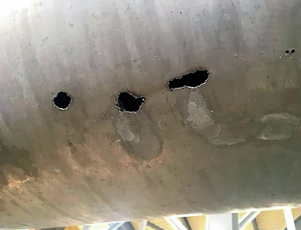
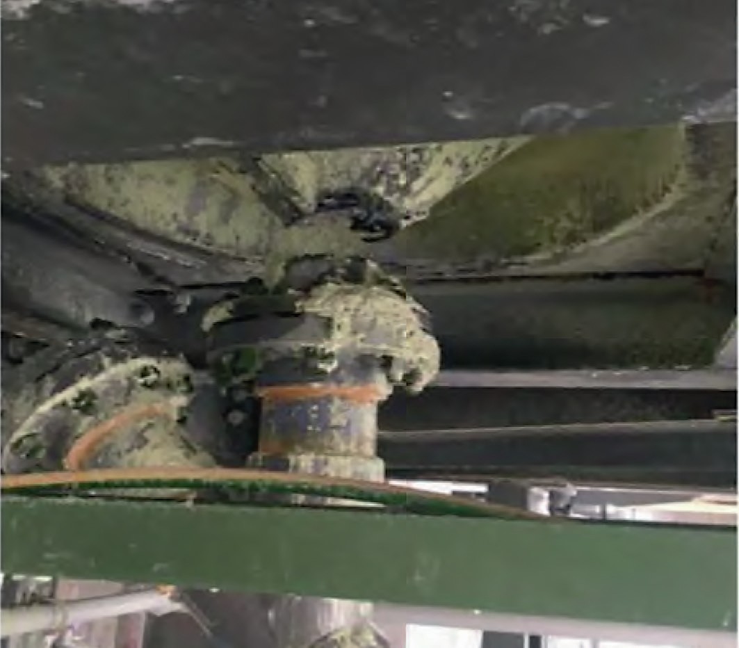
ADNOC Sour Gas operates 12 No. GXM1 sulphur granulation units as part of the Shah sulphur granulation plant. The first indication of corrosion on the wet scrubber exhaust ducts was reported on August 2016. In 2017, ADNOC Sour Gas noticed excessive corrosion in the GX plenum chambers, lower sections of the exhaust stacks, below the exhaust fan discharge line and in the scrubber inlet and outlet ducting in the sulphur granulator units (Figs 1 and 2).
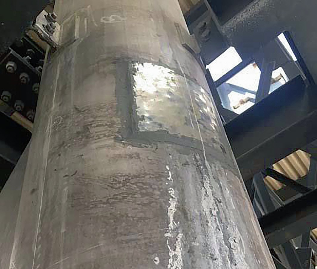
Since the problem was at the initial stage, the corroded areas were repaired using patch plate and putty in consultation with the vendor (Fig. 3). Later the decision was made to replace the corroded areas with more resistance material.
In mid-2018 an RCA was undertaken to understand the cause of the corrosion. The RCA indicated that low pH process water is carried through the wet scrubber discharge and is later condensed or deposited on the duct walls. The original ducting is made from 6-mm thick aluminum grade 6061-T6.
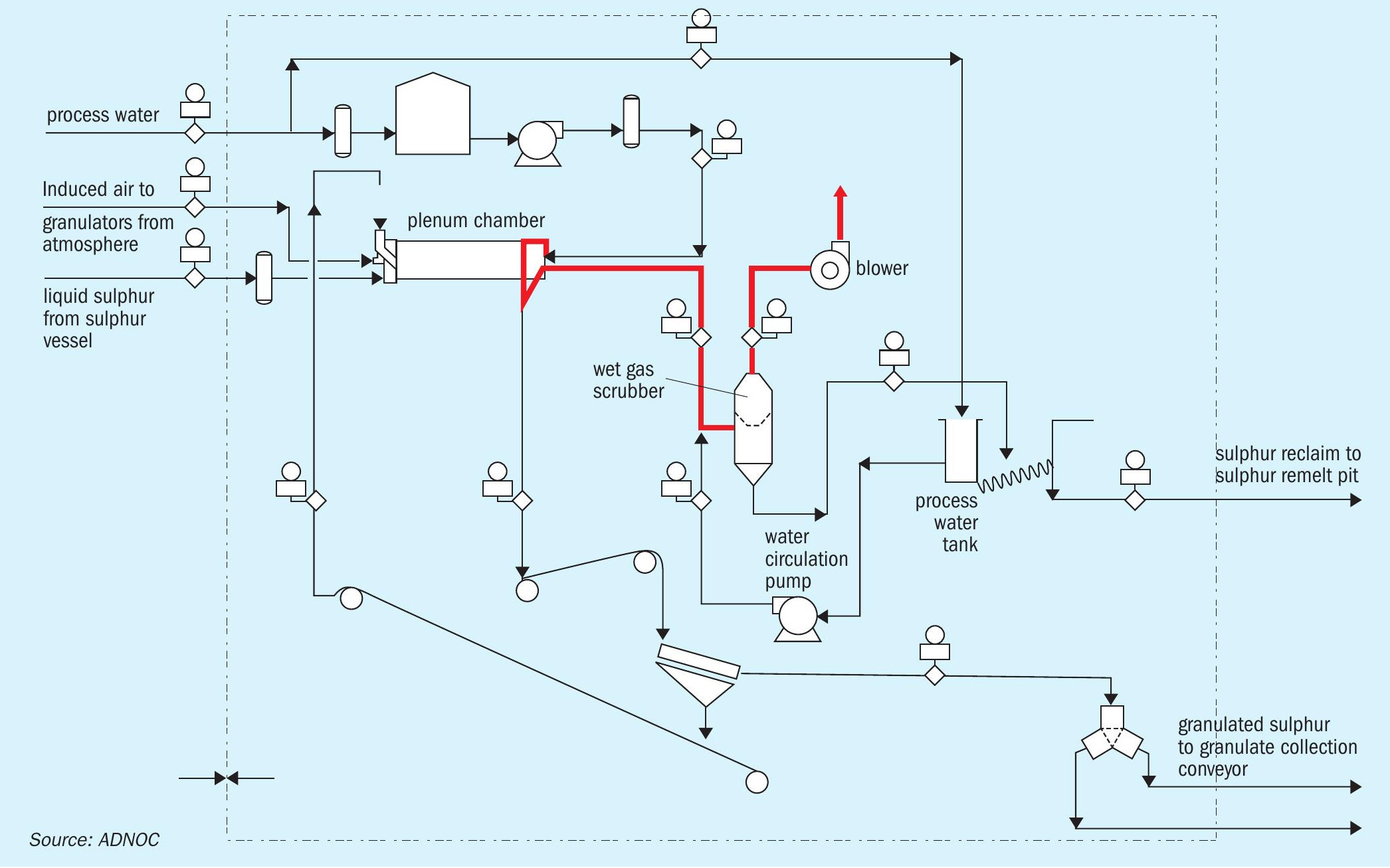
Fig. 4 is a typical schematic diagram showing the affected area/piping marked in red in the granulation unit.
Overview of existing granulators
The Shah Plant of the Abu Dhabi Gas Development Company (ADNOC Sour Gas) is located 210 km Southwest of Abu Dhabi City. This facility consists of onshore wells and production systems, gathering and transfer pipelines, a gas processing plant, product pipelines, and a Sulphur granulation plant. The sulphur granulation plant is located approx. 15 km from the main gas plant.
The 12 sulphur granulator units consist of the following major sub systems:
- sulphur filter;
- sulphur day tank;
- granulation drum;
- vibration screens;
- collection conveyor;
- scrubbers;
- exhaust unit.
Process details
Liquid sulphur from sulphur storage tanks is fed to the sulphur granulation plant and atomised in the granulator drum. Process water is sprayed through a sparger to atomise the sulphur and form sulphur granules. The sulphur granules are collected at the end of the granulator and sent to export/ rail loading. The sulphur fines along with water vapour from the granulator drum are sucked into the wet scrubber. Vapours are vented from the top through FD fans and wet sulphur fines are collected in setting tank (TK-5103) where water and sulphur are separated. The separated water is again recirculated as scrubbing water to the wet scrubber. Periodic draining of water from TK-5103 is required to control the pH above 5 of circulating scrubber water, as per the unit operating manual. The collected sulphur fines are sent to the remelter pits.
A sample point is provided at the cooler (7030-E-5101) and a pH analyser (7030AT-5500) is provided on the common discharge line of the wet scrubber recycle pumps (7030-P-5103A/B). Low pH alarm is set at 4. Normally, the process water pH is between 7.5 and 8.5 in the storage tank.
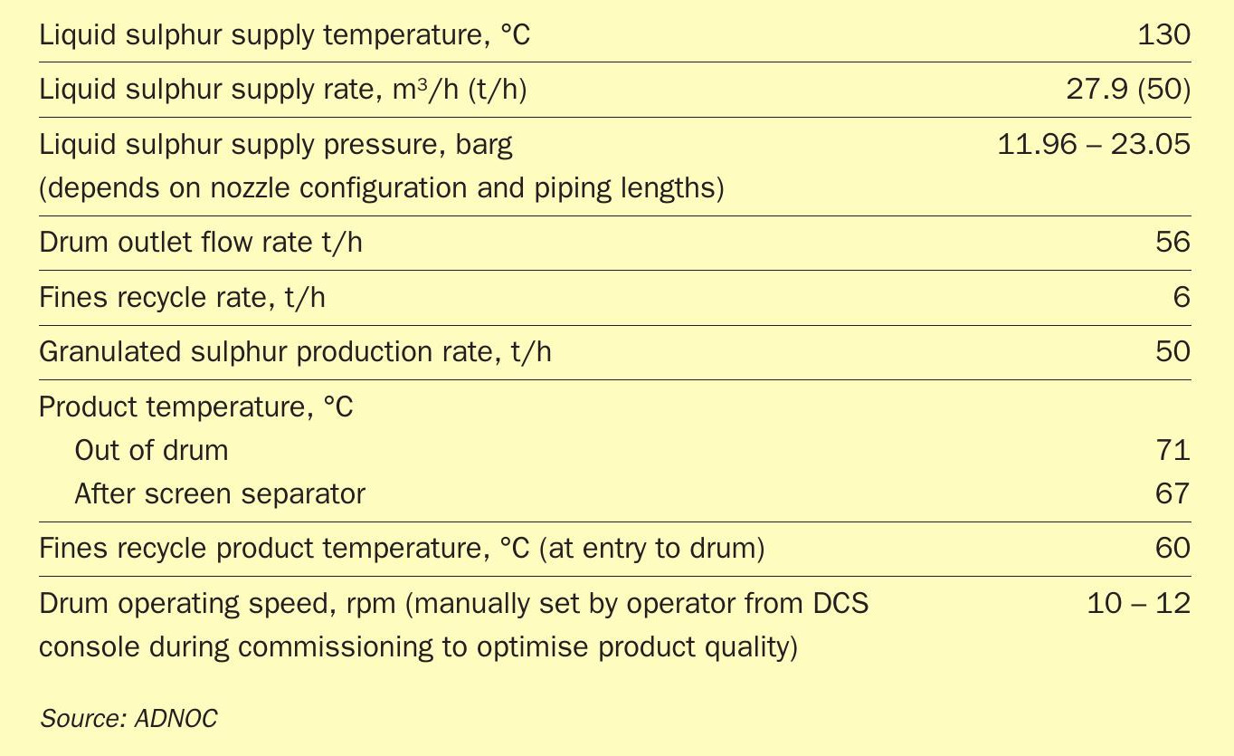
The design process operating conditions are shown in Table 1.
Water specifications
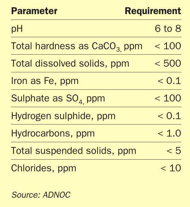
Process water generated from the reverse osmosis unit is used for makeup in the process water tank (TK-5103), which is used in the wet gas scrubber. The specification for the process water used is shown in Table 2.
In 2016, there was a proposal to switch over from process water to utility water, however this was stopped after a short period as the chloride content in utility water could initiate pitting corrosion in the aluminium and SS component.
Evaluation of granulators
The problem was raised to the vendor for route cause analysis. The company has also carried out internal inspections on corroded samples drawn from the plant. The outcome of the analysis includes:
The material of construction of the affected piping of the granulator is 98% aluminium (ASTM B209 grade 6061). This is the recommended material by the licensor ENERSUL.
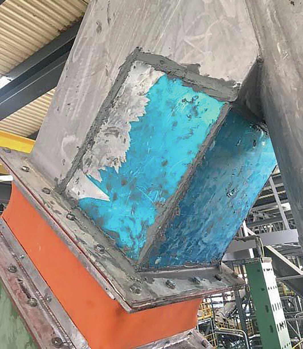
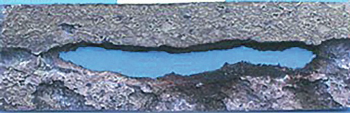
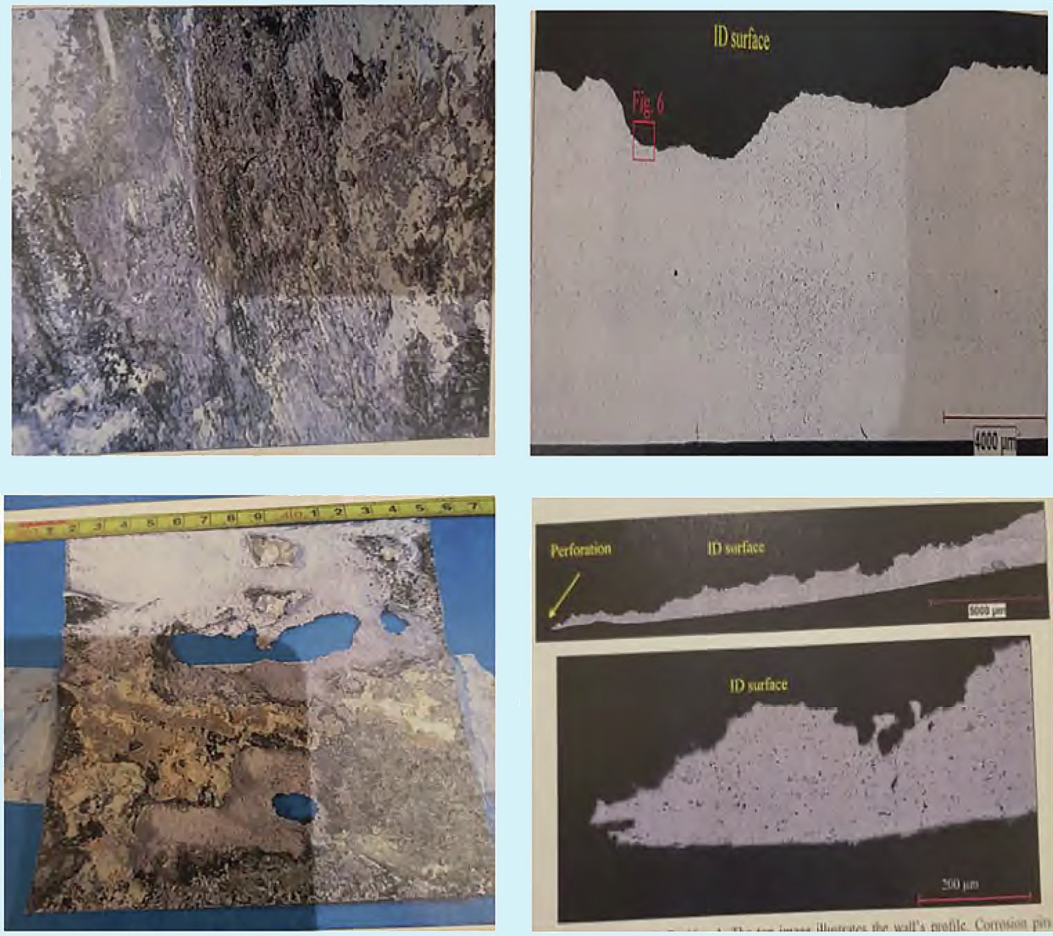
The corroded surface of the piping internal has shown deep corrosion (Fig. 5) leading to material loss.
Failure mechanism
The reason for such failures is related to two phenomena, acid corrosion and carbonate/chloride corrosion (water quality – dissolved carbonates etc. in water.
Acid corrosion
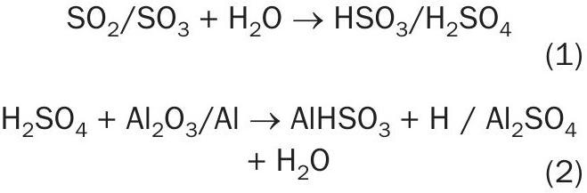
When dissolved acid gases (SO2 and SO3 ) in the liquid sulphur feed to the granulators or generated in the granulator come into contact with water a weak acid is formed (see equations 1 and 2).
This has been confirmed by operation as the pH level was found to be below 4.
The acid environment was the root cause of the corrosion of the aluminium piping.
Wet sulphuric acid corrosion and erosion
Water and SO3 have a good affinity for each other. When water is available, they combine rapidly to form sulphuric acid (H2SO4). The low pH acidic water is a major factor associated with this corrosion mechanism. The low pH water has a devastating effect on the life of the components handling them if they are not immune to this type of damage. Since the existing material was aluminium, it can potentially damage the protective aluminium oxide layer (Fig. 6). The situation is aggravated further by higher flow rates which can also cause erosion especially at bends.
Carbonate /chloride corrosion
The SO2 generated from the granulator operation was building up acidity through the plenum chamber, downstream of the duct and scrubber system in the presence of water and moisture, resulting in aluminium corrosion. Various options such as ADWEA water were tried to absorb the acidity but it did not help. The material selected should not be dependent on water quality.
Comparison of two granulation units in two different fields
A comparison was conducted in order to conclude the reason of the corrosion phenomena in the granulation unit. The two fields had a similar problem regarding water quality, where the pH drops below 4 for short periods of operation. However, the damaged areas in Field X were different to that of the Shah granulation units. Fig. 7 shows field samples where the wall thickness has been significantly affected. The type of corrosion in Field X is termed erosion corrosion whereas in the Shah granulation units it is severe intergranular corrosion (typical of acid attack).
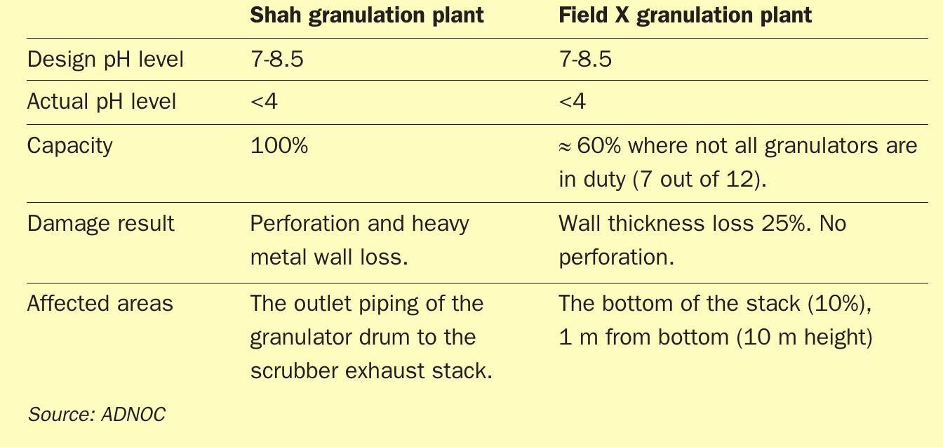
Table 3 demonstrates the main differences between Field X and Shah granulation plants.
From Table 3 it can be concluded that the material degradation issues in the Field X and Shah granulation plants are completely different from each other and cannot be compared. As a result, the mitigation action for Field X is to cut and replace the corroded bottom section of exhaust stack (1 m from bottom) with like-for-like material − aluminum 6061 T6 using flange and bolt (replaceable part). The bottom section (x4) will be kept ready with internal coating and will be replaced as and when required. This option was selected as they have redundancy of units (only 7 out of 12 are in use at a time).
Engineering studies
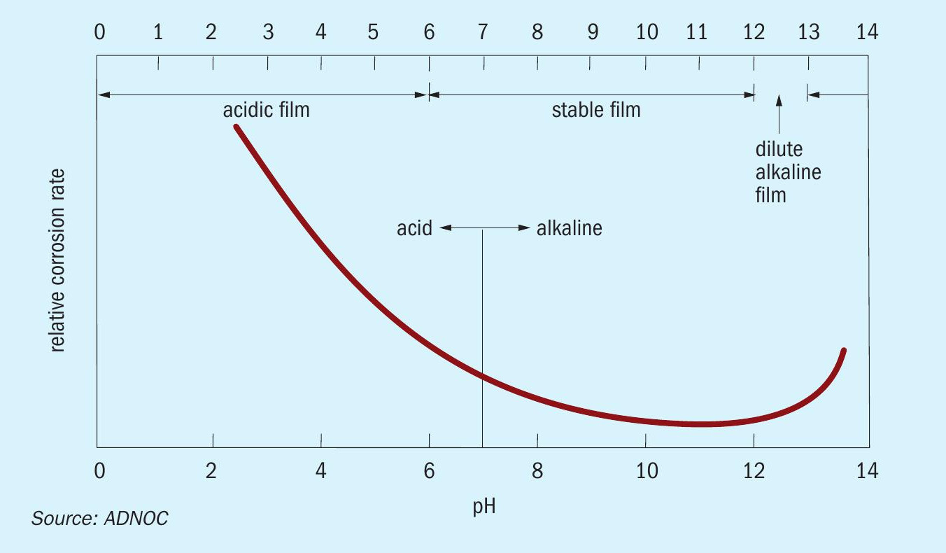
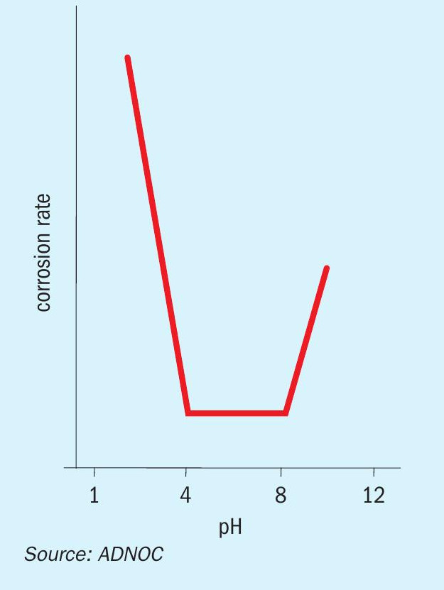
The corrosion rate of aluminium tends to increase significantly below a pH of about 4 as shown in Fig. 8. In addition, as shown in Fig. 8, the corrosion rate of aluminium increases in environments where the pH level is above 8.
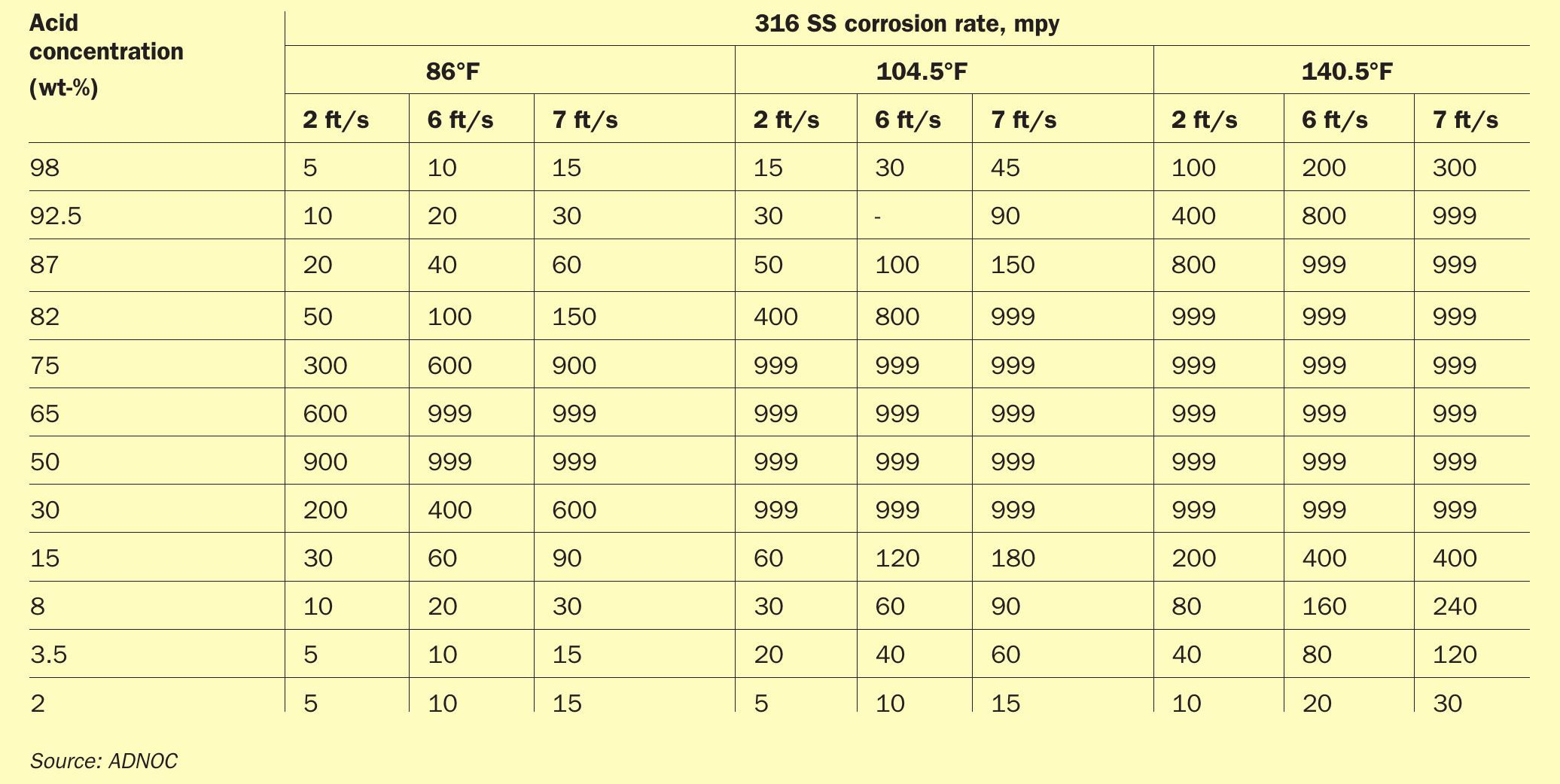
As shown in Table 4, SS 316L behaves differently under different concentrations of H2SO4 with respect to different temperatures in the presence of free liquid1 . The concentrations include the following typical ranges:
- dilute acid concentration: 0 to 20%
- intermediate acid concentration: 20 to 70%
- strong acid concentration: more than 70%
However, the above ranges are only applicable for sulphuric acid handling and storage systems which involve frequent dilution and concentrated H2SO4 cycles in the presence of free liquid water. The possible cause of previous liquid carryover within the outlet duct from the plenum chamber could be either due to condensation (with lack of insulation) or due to liquid carryover as the plant was operating at maximum capacity. As shown in Fig. 4, within the sulphur granulation unit, the outlet duct and plenum chamber handle only fine granules mixed with air with no free liquid. Therefore, the handling of H2SO4 will not be a major concern for stainless steel in this part of the process stream. Thus, the iso corrosion curves2 involving H2SO4 concentration for stainless steels is not applicable. This is also in line with the condition of SS 316L in manufactured wet scrubbers and associated assembly such as inlet venturi, elbow etc installed within the 12 GX units. Overall, the recommended metallurgy applicable for the plenum chamber and outlet duct from the plenum chamber is stainless steel. The grade of stainless steel suitable for the plenum chamber and outlet duct from plenum chamber is ASTM A240 SS 316L with at least 2.5% molybdenum content.
At the outlet duct from the wet gas scrubber, the presence of liquids can be from condensation or carry over from the process. It can also be due to uprating of the plant at maximum capacity. The corrosion mechanism will be wet sulphuric acid corrosion and erosion. The outlet duct from the wet scrubber transports exhaust gases such as SO2 and H2S. Overall, considering the corrosiveness of fluid towards the aluminium stack, it would be prudent to use a more resistant material. Based on an extensive literature review, glass-fibre reinforced vinyl ester (GRVE) was selected. Moreover, the cured resin glass transition temperature (Tg) of GRVE shall be greater than 120°C and a UV stabiliser additive shall also be added to the resin for external UV protection of the GRVE stack. Therefore, Derakane 470-300 was selected as the GRVE grade suitable for this service.
The flowrate considered for materials selection was 18,000 Nm3 /hr. From the corrosion perspective, the main issue before was the increased flow rate pushing the corrosion problem downstream, i.e., forcing acidic water into the duct and stack where it would corrode the aluminum. The SS 316L wet scrubber and inlet venturi duct to the wet scrubber did not seem to be affected by this water and should be the same for the stainless steel plenum chamber and outlet duct from the plenum chamber. It is also worth considering the velocities to evaluate the potential for erosion. Considering the previous and latest flowrate, the increase in velocity at the inlet duct to the scrubber is not significant. Erosion would not be applicable at these velocities, especially when GRVE is recommended for the exhaust stack and outlet duct of wet scrubber.
Calculations
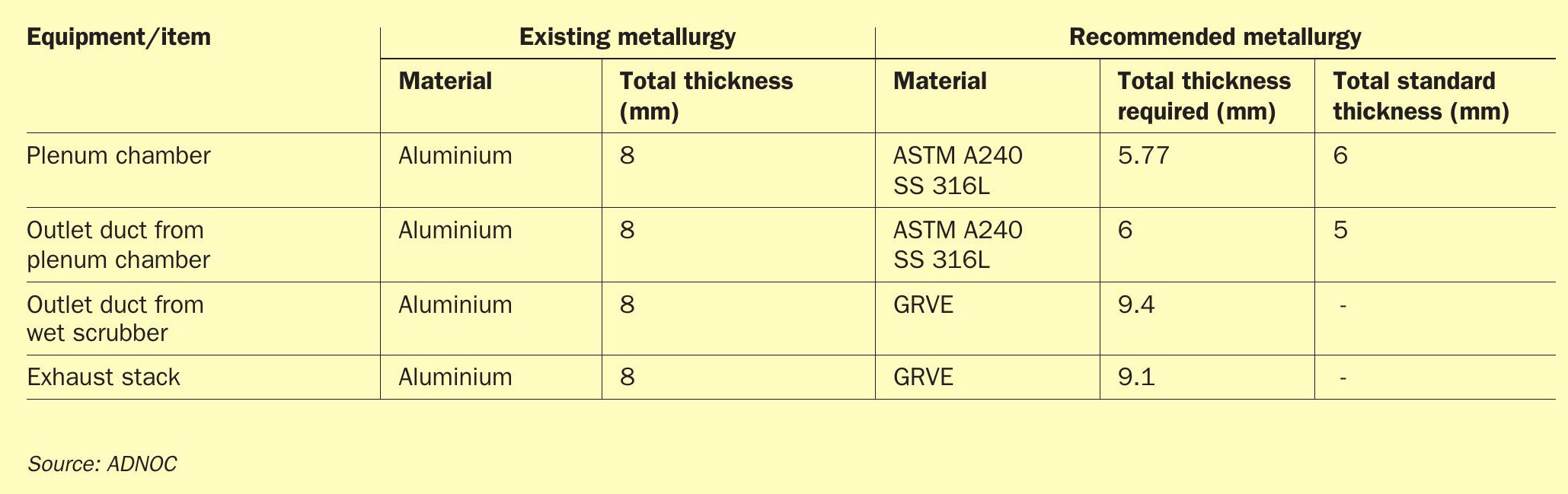
The thickness of the aluminium was 8 mm, ADNOC Sour Gas requested the contractor to conduct a detailed study to confirm the thickness of SS 316L and GRVE. Table 5 shows the total thickness for the plenum chamber, outlet duct of plenum chamber, outlet duct from wet scrubber and exhaust stack. The total standard thickness given in Table 5 is for the plate material of respective ASTM A240 SS 316L grade.
The metallurgy recommended in Table 5 is for a service life of 30 years for the respective items. It is also recommended that a H2 SO4 resistant veil or single protection layer is added to the GRVE to protect against the occasional presence of H2 SO4 . The glass transition temperature for the cured resin of GRVE should be greater than 120°C and a UV stabiliser additive should also be added to the resin for external UV protection of the GRVE stack. Derakane 470-300 is the recommended commercial resin grade of GRVE suitable for the current service in the outlet duct of plenum chamber and exhaust stack. The higher GRVE thickness at the outlet duct from the wet scrubber compared to the stack is due to the partial vacuum conditions within the duct.
Conclusion
In conclusion, aluminium components were replaced based on the engineering study. As the results showed and as highlighted in Fig. 8, aluminium is not a suitable material when the process and operation cannot be maintained at a pH level of 4 and above. In addition, from a corrosion perspective, the main issue before was the increased flow rate pushing the corrosion problem downstream, i.e. forcing acidic water into the duct and stack where it would corrode the aluminium. The SS316L wet scrubber and the inlet venturi duct to the wet scrubber was not affected by this water and now it’s the same for the stainless-steel in the plenum chamber and the outlet duct from the plenum chamber. Considering the previous and latest flowrate, the increase in velocity at the inlet duct to the scrubber is not significant. Therefore, erosion is not applicable at these velocities.
Outcomes
The outcome, as concluded by the commissioned granulation units and the engineering study, demonstrates that aluminium with a low pH level below 4 cannot withstand this process and the corrosion rate was accelerated. Therefore, stainless steel as in the wet scrubber and inlet venturi which were originally constructed with SS 316 are in good condition since the commissioning of the granulation units in 2014. Important lessons have been learned from this study that could be relevant for other projects and plants. The current arrangement with upgraded material will assist all new projects to design plants either with enough unit redundancies for routine cleaning or to use more resistant material to combat corrosion.
References
Acknowledgement
This article is based on the paper “Material Upgradation in Sulphur Granulation Plant Due to Severe Corrosion in Aluminum Components” by Mohamed Al Ameri, Nuha Al Hajeri, Shyam Pandey, and Antonio Madeina, ADNOC Sour Gas, presented at the Virtual Abu Dhabi International Petroleum Exhibition & Conference held 9-12 November 2020.