Nitrogen+Syngas 379 Sept-Oct 2022
30 September 2022
Urea plant revamping for energy savings
UREA PLANT REVAMPING
Urea plant revamping for energy savings
Casale reviews urea plant revamping process schemes and successful case studies for energy savings and TOYO discusses its latest revamping technologies including application of the new generation low-pressure, energy-saving ACES21-LP™ process.
CASALE
Casale urea plant revamping schemes for energy savings
Since April 2021, alongside the progressive improvement of the SARSCoV-2 pandemic and consequent recovery of the economy worldwide, the price of natural gas has surged to levels not seen for almost 20 years. In some regions the high prices for energy and raw materials have had a major impact, drastically eroding the operating margin of many fertilizer manufacturers. For example, in Europe, where natural gas in August 2022 is ten times more expensive than it was in early 2021, the cost of urea production has skyrocketed.
In this scenario, which according to several analysts is not going to improve any time soon, reducing the energy intensity of fertilizer production processes is crucial for keeping operating costs under control and to recover profitability. In a typical breakdown of urea production costs, ammonia accounts for 80-85%, whereas energy (steam and power) typically accounts for “only” 10-16%. With the urea price as in 2020, the energy bill of an average urea plant would total 25-40 $/t. Even a significant reduction of the energy consumption, 20-30% less, would yield a “meagre” 5-10 $/t extra profit. In such market conditions, energy saving alone is seldom a sufficient driver for complex and costly plant revamping projects which generally require an associated relevant capacity increase to provide attractive returns. A different scenario is represented by revamping projects backed or demanded by authorities to reduce the environmental impact or carbon footprint of fertilizer production. However, in the current urea market scenario, with spot prices of urea at around 800 $/t and natural gas as high as 200 $/MWh, energy saving projects yield a very attractive return time, especially for vintage and high energy consuming plants.
Revamping of urea plants has always been part of Casale’s DNA, which led to the development of specific process schemes for energy saving. During almost four decades of activity in the urea business, Casale has implemented its revamping schemes to vintage plants of different design, covering almost all process technologies. In the following review, a few process schemes are presented together with the mention of cases studies where they have been successfully applied.
Revamping Total Recycle plants: The HEC process
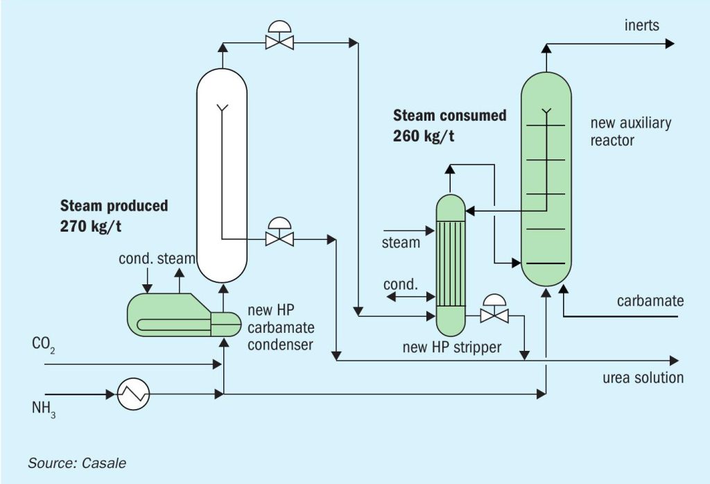
The High Efficiency Combined (HEC) process was developed in the 1990s specifically for the revamping of vintage Total or Partial Recycle plants. Its name refers to the main feature of the process scheme, which foresees the combination of a once-through high-conversion synthesis step with a reactor fed only by recycled carbamate. Fig. 1 shows the overall scheme of the synthesis section with the new items of equipment marked in green, consisting of a new auxiliary reactor, a HP carbamate condenser and a HP stripper. The HP stripper requires 20 bar(g) steam, but the HP carbamate condenser generates LP steam at 5.5 bar(g) which is used in the downstream purification sections. The overall CO2 conversion of the HEC synthesis section is about 72-73% which represents a drastic improvement compared to a typical Total Recycle averaging 60-64%. Thanks to the increase in conversion of the synthesis section, the demand for MP steam reduces from 1550 kg/t to 1,100 kg/t (about 30% saving).
Another major advantage of the HEC process is the possibility to maintain the entire existing purification section. The scope of revamping can thus be limited to a few pieces of equipment in the HP section which can be conveniently installed with the plant in service. The shutdown time needed to implement the modifications can be narrowed down to slightly more than a conventional turnaround. The increase in conversion of the synthesis section also allows easy plant capacity increase of up to 30-40% without affecting the purification and recovery section. The combination of energy saving and, if desired, capacity increase leads to extremely attractive investment return time due to the relatively low investment cost.
Energy savings for self-stripping plants
The so-called “self” or “ammonia” stripping plants represent a major share of the urea plants currently in operation. Since their introduction in the 1970s the conceptual process scheme has maintained the original features, but a few modifications have been gradually implemented to improve the specific energy consumption. Nowadays, modern self-stripping plants have reached a degree of heat integration that allows specific MP steam consumption below 700 kg/t (excluding the consumption of the CO2 compressor). Since the backbone of the most efficient plants is pretty much the same as vintage plants, the modifications required to upgrade old high-energy consuming plants to the state of the art can be carried out without major capex allocation.
Casale has applied its experience in several total or partial revamping projects of ammonia stripping plants. Among the latest of relevance, it is worth mentioning the revamping of Trombay, India, urea plant. The plant, commissioned in 1982, in common with many plants of its kind built throughout the mid-1990s, did not implement any heat recovery strategy and relied upon the HP stripper to maximise the decomposition of unreacted carbamate to maintain the recycle of carbamate, and consequently water, from the downstream sections as low as possible. The operating philosophy required the bottom temperature of the titanium HP stripper to be as high as 210°C, generating a massive quantity of vapours to be condensed in the kettle HP carbamate condenser. The production of LP steam in the HP carbamate condenser was such that all the downstream 3.5 kg/cm2 g demand was fully covered. By contrast, the consumption of 22 kg/cm2 g steam in the HP stripper was proportionally high leading to an overall energy consumption above 1.1 Gcal/t (including the CO2 compressor). The revamping project, focused on energy saving, required the energy consumption to be decreased by 25% minimum.
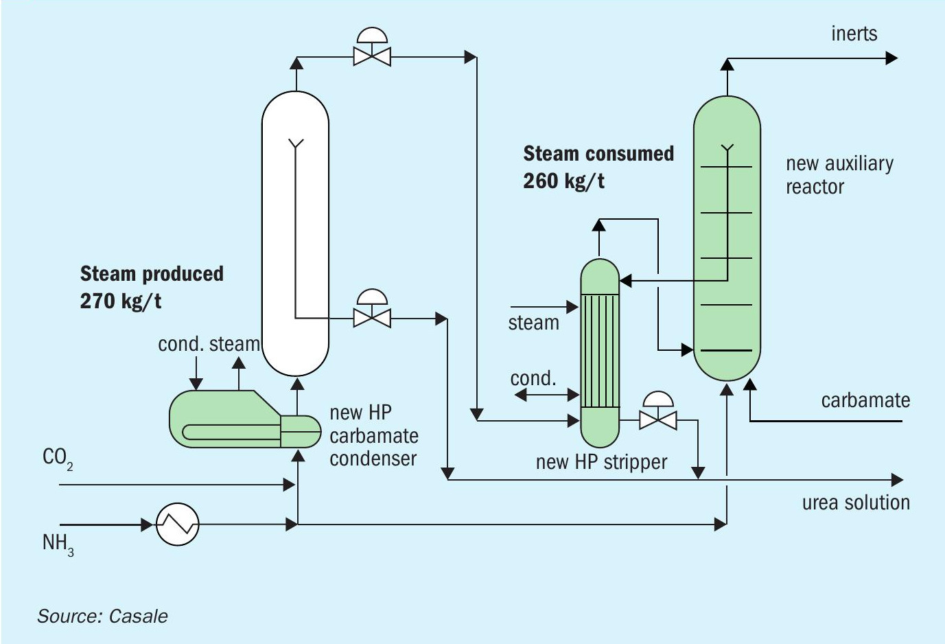
To achieve such a demanding target the revamping strategy was based on maximising the integration of heat sources and consumers to implement the highest heat recovery allowed by the temperature profiles. Meanwhile the demand for steam was shifted from medium pressure, extracted from the turbine, to low-pressure steam generated by the HP carbamate condensers. In the original plant design only two steam pressure levels were foreseen, 26 and 3.5 kg/cm2 g. The former level was used in the HP stripper and hydrolyser, whereas the LP steam was deployed to the decomposition stages, evaporators and distillation tower. In the revamping project an additional kettle-type HP carbamate condenser was installed downstream of the existing one. With a second HPCC it was possible to generate LP steam at 5.5 kg/cm2 g, deployed to users requiring higher temperatures, and 3.5 kg/cm2 g used for tracing, flushing and in exchangers requiring lower temperatures. Additionally, a steam condensate tank at 2.0 kg/ cm2 g was installed on the LP condensate return header. The low-low pressure generated steam is now thermo-compressed in a booster ejector using 5.5 kg/cm2 g and delivered to the process condensate distillation tower. Fig. 2 shows a schematic of the modified steam network.
A major advantage of steam produced internally at 5.5 kg/cm2 g is the possibility to add a new decomposition step directly downstream of the HP stripper. Urea solution from the HP stripper after flashing at 18 kg/cm2 g is subject to a new carbamate decomposition step carried out in a medium-pressure pre-decomposer. The pre-decomposer removes the additional carbamate due to the lower HP stripper bottom temperature, thus debottlenecking the existing MP decomposer. Thanks to the MP pre-decomposer, the MP decomposer can still be operated solely with steam condensate from the HP stripper, without the need for MP steam injection. For such purposes, Casale has designed a pre-decomposer with special internals for phase separation which avoids increasing the water entrained in the MP vapours.
To reduce LP steam requirements so that the entire plant consumption could be entirely satisfied with internally generated steam, a vacuum pre-concentrator was installed on the first stage evaporator. This solution has been widely applied in modern ammonia stripping plants where the heat released by carbamate vapours at medium pressure can be conveniently exploited for urea concentration in place of LP steam. Besides steam savings, adding a vacuum pre-concentrator has the added advantage of drastically reducing the duty required by the MP carbamate condenser and consequently the consumption of cooling water. The heat recovery performed by the vacuum pre-concentrator reduces the consumption of 3.5 kg/cm2 g steam by approximately 200-230 kg/t urea. This reduction is not enough to close the gap between consumed and produced LP steam. Therefore, two additional recovery steps were added. A new exchanger was installed to exploit the heat of condensation of low-pressure carbamate vapours and a second heat recovery exchanger was installed upstream of the reflux condenser in the wastewater treatment. The former is used for ammonia feed pre-heating, the latter as recycled carbamate preheater. The main purpose of these items is to increase the production of steam in the HP carbamate condensers and meanwhile debottleneck condensers in the LP and wastewater treatment sections with consequent saving of cooling water.
The revamping project was completed between December 2020 and February 2021. During the guarantee test run, the measured MP steam flow rate from turbine extraction (which accounts for all the process users including the hydrolyser) was lower than the guarantee value, achieving a reduction of specific energy consumption of about 27%. The recorded value is in line with the most modern urea plants, which places the revamped process scheme among the best available technology on the market. If compared only with ammonia stripping plants with prilling towers, the achieved specific consumption is the best performance commonly measured in India. Together with energy savings, the revamping project also attained a reduction of the ammonia specific consumption and a drastic improvement of the quality of the treated water which is now at BFW grade.
Revamping CO2 stripping plants: The MP section
One of the intrinsic features of the CO2 stripping process as it was introduced in the 1960s is the absence of a purification stage at medium-pressure. The removal of free ammonia (not bonded with CO2 in ammonium carbamate salts) carried out in the HP stripper allows the recovery of the remaining carbamate in a single low-pressure stage. At 3.5 bar(g) the temperature of carbamate formation is such that recovering the heat of condensation for any process use is scarcely practical. In most cases, such heat is lost to the cooling water. Moreover, the HP stripper requires up to 850-900 kg/t of steam at 20 bar(g) which is balanced by an even higher LP steam generation in the HP carbamate condenser; still, in the traditional CO2 stripping process, especially if granulation is the finishing method selected, excess LP steam is either exported or reinjected into the turbine.
For reasons such as these, in recent years several licensors have been adopting process schemes based on CO2 stripping technology, but with an intermediate purification step in between the HP stripper and the LP section. The advantage of these intermediate sections operating at medium pressure can be summarised as follows. Having a carbamate recovery step at a pressure intermediate between 10 to 20 bar(g), the stream from the HP stripper can contain a higher fraction of carbamate and a fraction of free ammonia is also tolerated; this translates into the possibility to lessen the degree of decomposition and consequently the steam consumption in the HP stripper. Additionally, carbamate decomposition at medium-pressure can be carried out with steam at 4-8 bar(g) and carbamate formation follows a temperature profile which allows the implementation of a heat recovery strategy, for example, to concentrate urea solution.
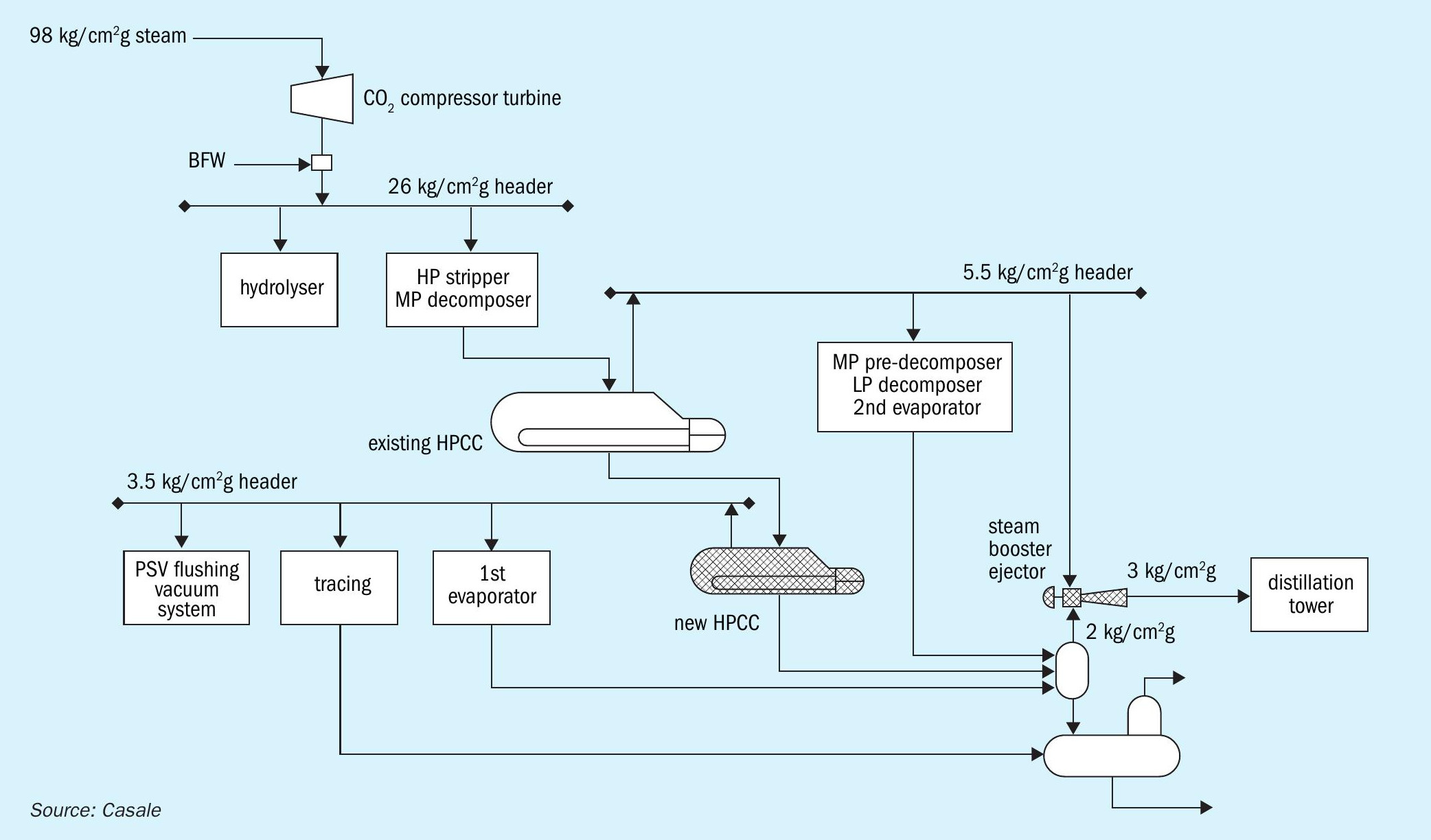
Fig. 3 shows the process scheme of the MP section adopted by Casale for new or revamped CO2 stripping plants. The pieces of equipment included in the section are a MP decomposer, a MP carbamate condenser with its dedicated tempered cooling water loop and a urea concentrator. This section is operated at approximately 10 bar(g) which allows use of LP steam (generated or mildly thermocompressed) in the MP decomposer and exploits the heat of condensation of the carbamate vapours to promote urea solution concentration in a vacuum evaporator. This process scheme was adopted for the revamping of a CO2 stripping plant in Russia in 2018 where it was desired to reduce the high MP steam consumption, due to integration with a melamine plant, by at least 200 kg/t (approximately 20%). For such revamping, the equipment installation cost was contained by repurposing an idle HP stripper and an idle HP carbamate condenser, which were conveniently recycled as an MP decomposer and MP condenser respectively. In addition, the existing HP carbamate pumps were maintained and revamped to increase the suction pressure, which was considerably less expensive than replacing them with new machines.
In the same revamping project, together with the MP section addition, heat recovery was implemented on the tempered cooling water loop of the HP scrubber. Specifically, tempered water at 130°C has been used for pre-heating the urea solution upstream of the final concentration in the vacuum section. Such schemes are nowadays commonly applied in modern plants and can be an attractive option for vintage plants.
TOYO ENGINEERING CORPORATION
Revamping urea plants with ACES21-LP™ for energy savings and plant cost reductions
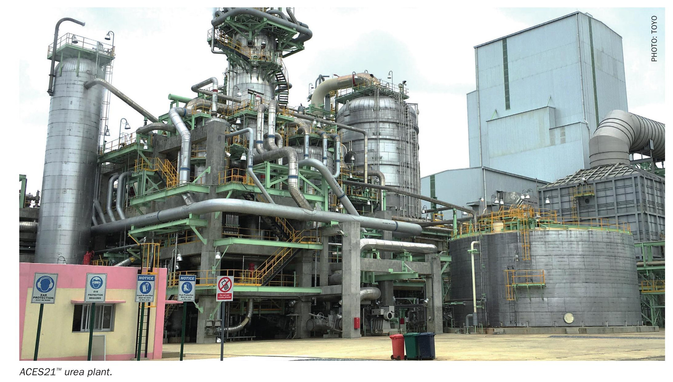
Toyo Engineering Corporation (TOYO), a global leading engineering contractor and urea process licensor, has developed TOYO’s proprietary urea processes since the development of the partial recycle process in the 1950s. Using its expertise, advanced technology and novel thinking, TOYO established ACES21® in the late 1990s and has since been awarded 16 ACES21® projects, including two 4,000 t/d urea projects for Indorama Eleme Fertilizer and Chemicals Limited (IEFCL) which is the world’s largest single train urea plant. TOYO has been working on further improvements and innovations in its proprietary urea processes and has developed ACES21-LP™ , the next generation ACES21® , which was introduced in Nitrogen+Syngas July-August 2022. This article introduces TOYO’s idea and experiences for revamping a conventional urea plant, including an example of utilising ACES21-LP™ technology.
Upgrading existing ACES21® urea plants with the ACES21-LP™ concept
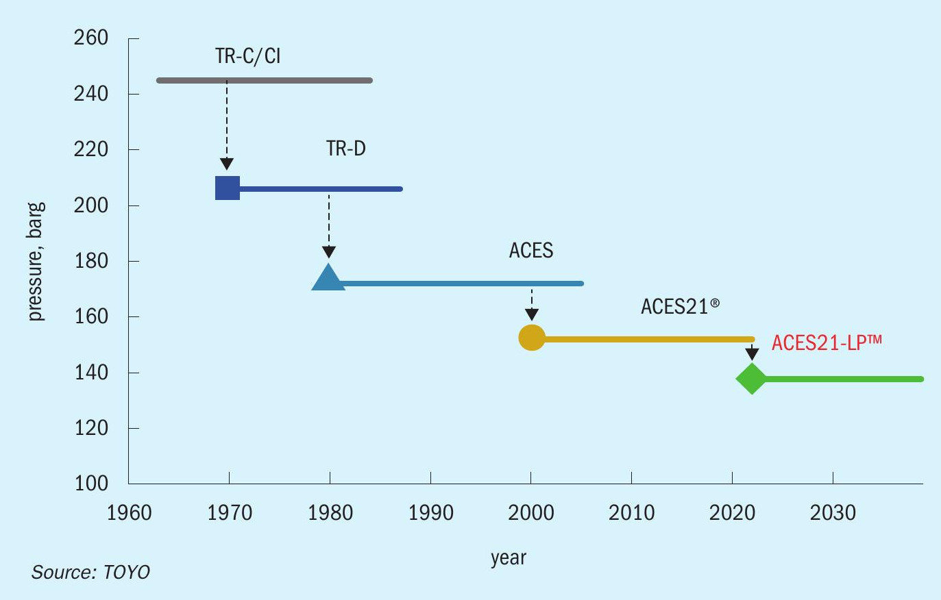
TOYO has developed the next generation ACES21® process, ACES21-LP™, to realise further energy savings and plant cost reductions, while maintaining all salient features of the current ACES21® process. Fig. 1 shows the history of how TOYO has lowered urea synthesis pressure over the past 60 years. The urea synthesis pressure has been lowered step-by-step from around 240 bar to 152 bar through technology advances. The ACES21-LP™ concept lowers the urea synthesis pressure one step further to 136 bar. The key to realising the benefits of ACES21-LP™ is the sophisticated application of DP28W™, conventional duplex SS and 316L SS to the synthesis section in combination with reduced passivation air. The simple and sophisticated concept of ACES21-LP™ enhances the well-known features of the current ACES21® process in terms of the following aspects:
- lowest synthesis pressure among commercial urea processes owing to the uniquely optimised synthesis conditions and reduced passivation air requirement;
- highest CO2 conversion among advanced modern urea processes;
- further energy savings (less opex) due to 5-10% lower power requirements of the CO2 compressor, ammonia and carbamate pumps;
- less capex owing to the milder mechanical design conditions of the synthesis equipment (synthesis section HP equipment cost reduced by 5-10%).
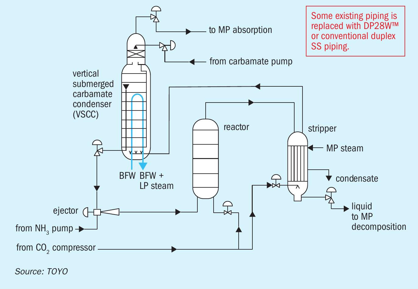
Since the basic process scheme of the current ACES21® process is retained in ACES21-LP™, this concept can be easily applied to currently operating ACES21® plants with minor modifications. As shown in Fig. 2, to convert the process to ACES21LP™ requires some replacement of stainless steel piping material with DP28W™ or conventional duplex SS in areas that are most corrosive. Since the material selected in other areas of ACES21®, including the existing synthesis equipment, shows sufficient corrosion resistance even under the new operating conditions, only minor modifications are required.
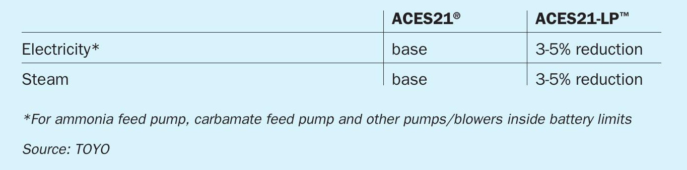
Thanks to the lower operating pressure, opex can be reduced compared to the original ACES21® condition. Table 1 shows a comparison of the expected power and steam consumption between ACES21® and ACES21-LP™. Both are lowered by 3-5%, which is remarkable considering the conventional ACES21® process has been the most energy-saving process among the licensors.
TOYO’s concept to apply ACES21-LP™ is to tailor the selection of a suitable and reliable material according to the service conditions, specifically considering the corrosiveness of the environment, and not to employ costly material to all parts unnecessarily.
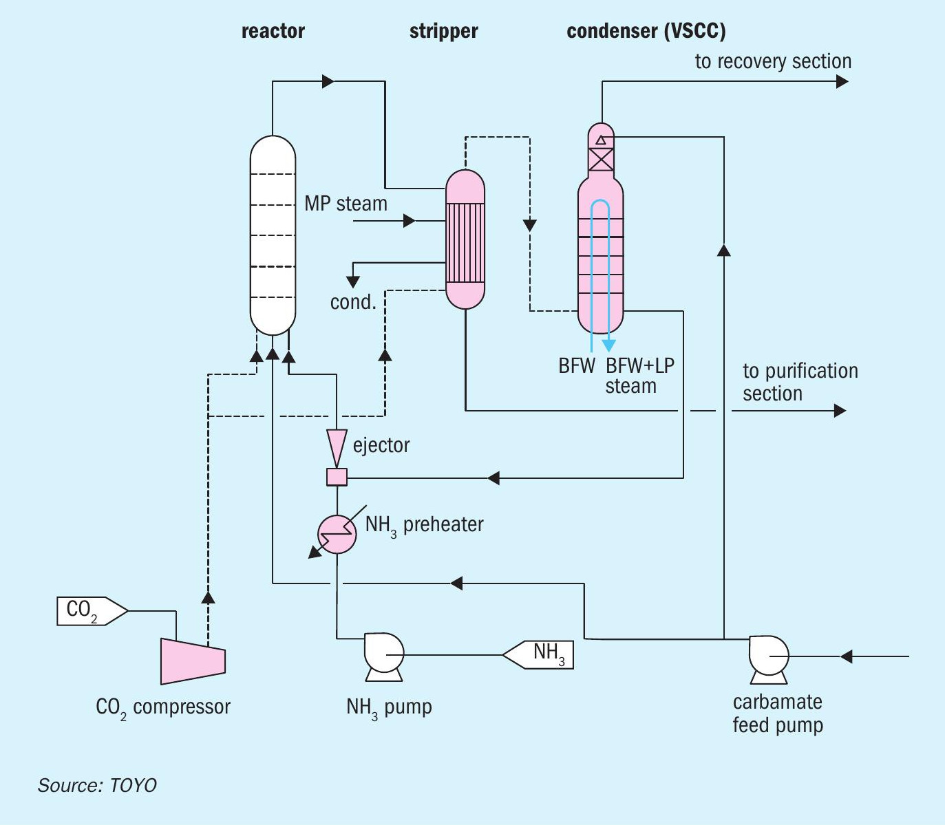
Upgrading CO2 stripping urea plants with the low-pressure concept
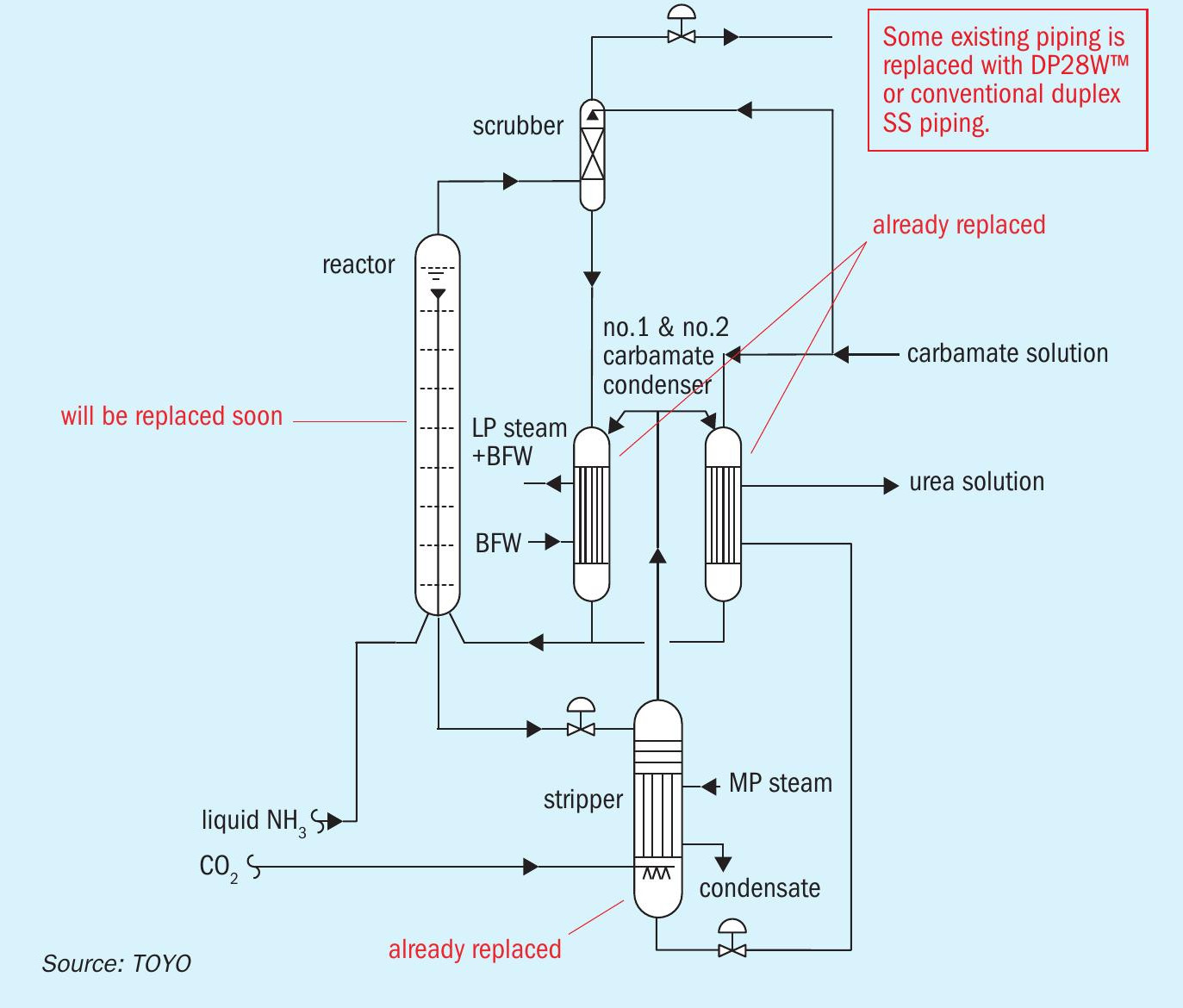
The ACES21-LP™ concept can also be applied to currently operating conventional CO2 stripping urea plants like the TOYO ACES process. Fig. 3 shows a typical modification scheme to upgrade the existing ACES plant using the ACES21-LP™ concept. All TOYO ACES plants have been operated for more than 20-30 years; therefore, the synthesis equipment needs to be replaced with new equipment in which DP28W™ is selected as the material of construction for the lining or tubes. For instance, in one ACES plant, the stripper and carbamate condensers were replaced with new ones made of DP28W™ based on the above concept and the reactor will soon be replaced with a conventional duplex steel-lined reactor. In such a case, the plant can be upgraded to the low-pressure process by replacing only some limited piping with piping made of DP28W™ or conventional duplex stainless steel piping.
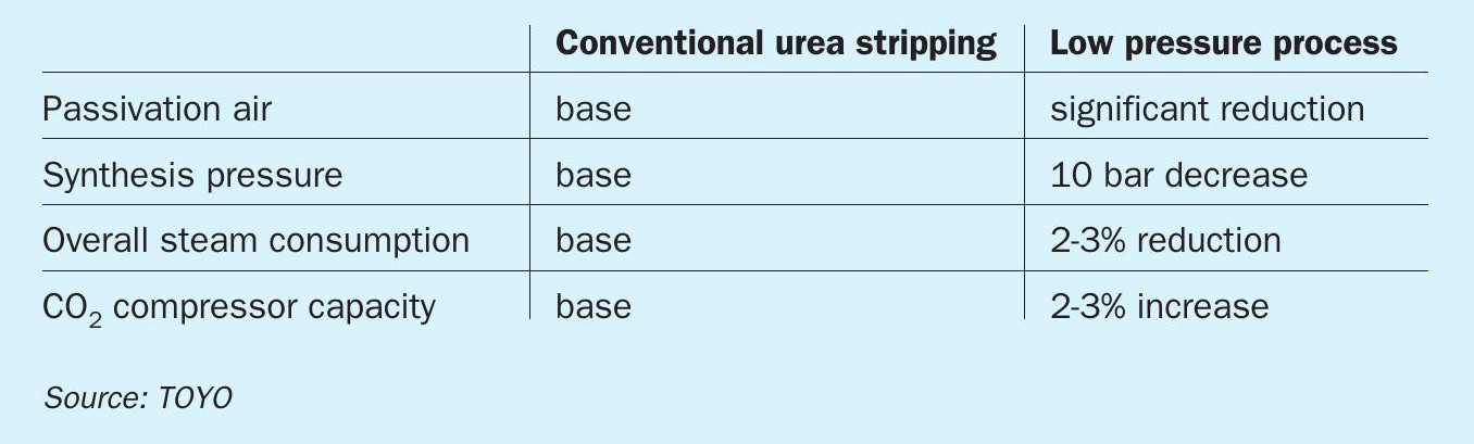
By making modifications to lower the synthesis pressure, plant owners will enjoy energy savings. Table 2 shows a comparison of the expected process performance before and after renovation to the low-pressure process. As shown in the table, the synthesis pressure is reduced by 10 bar while maintaining the N/C and H/C ratios in the reactor as in the present condition, and the overall steam consumption is reduced by 2-3%. It should be noted that, instead of energy savings, the plant capacity can be increased by 2-3% by using the extra margin of the CO2 compressor because the head and power of the compressor are reduced thanks to the lower synthesis pressure.
Conversion of existing total recycle urea plants to ACES21® /ACES21-LP™
ACES21® and/or ACES21-LP™ can also be applied for the renovation of old vintage total recycle urea plants. Fig. 4 shows the modification scheme in the synthesis section to convert the total recycle plant to ACES21® or ACES21-LP™. The equipment illustrated in pink (the stripper, carbamate condenser and HP ejector) is added to the synthesis section; however, the existing reactor can be reutilised as it is. By virtue of this modification, a capacity increase of 50% can be achieved with energy savings of more than 30%, keeping the existing ammonia feed pump and carbamate feed pump without any modifications. The option to replace or modify the CO2 compressor to increase its capacity depends on the revamping concept. For example, if the aim is to increase the production capacity or to improve the maintenance frequency of the existing reciprocating compressor, replacement of the compressor with a new centrifugal type may be selected.
Utilising the opportunity to renovate the urea synthesis section, TOYO can recommend converting the existing crystallisation process to a new vacuum evaporation process to concentrate the urea solution. Many vintage urea plants have applied the crystallisation process and such an aged system needs frequent cleaning which requires periodic shutdown of the urea plant. In the case of the vacuum evaporation process, continuous operation is achieved without cleaning, which improves the operability and maintainability of the plant. Besides being easier to operate with less maintenance for cleaning there is also reduction in power consumption compared to the crystallisation system.
Efficiency/reliability increase by replacement of urea synthesis equipment
The synthesis equipment in urea plants that have been operated for more than 20-30 years will have inevitably deteriorated and require replacement according to the circumstances. In such a replacement case, TOYO has applied the following concept offering its best solutions to plant owners:
- selection of suitable and robust materials, such as DP28W™, to make new equipment more reliable;
- application of the latest design for internals, such as an improved baffle plate in the reactor and/or a swirl in the stripper, to increase efficiency and reliability;
- procurement by TOYO itself, depending on conditions, to assure the quality of all the details required to eliminate unexpected flaws caused by manufacturers, through advanced and efficient inspection.
The following typical example refers to excellent experience for a stripper replacement. In this case, a plant owner had faced difficulties caused by an aged stripper installed in a conventional CO2 stripping process and wanted to replace it. TOYO made recommendations for a new stripper according to the following concept:
- application of the latest type of stripper for ACES21® to enhance reliability and efficiency;
- selection of DP28W™ as the material of construction for parts in areas that are most corrosive.
The plant owner agreed with all of TOYO’s recommendations.
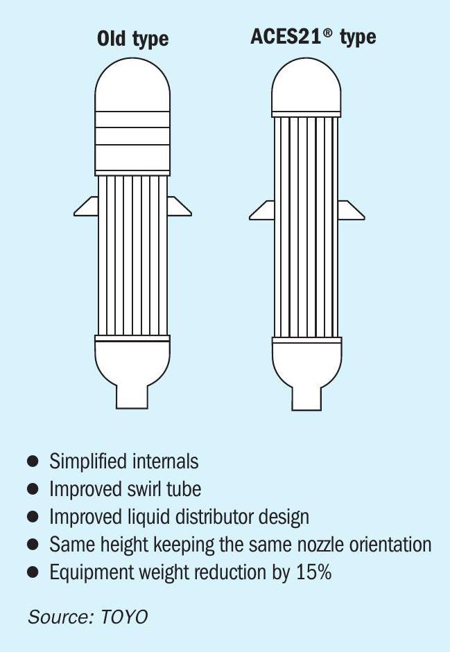
Fig. 5 shows the outline of a general drawing for an old and a new stripper. To reutilise the existing foundation and the nozzle orientation, the dimensions of the new stripper was adjusted to fit the existing dimensions. Remarkably, the weight of the new equipment is 15% lighter because of its simple internals while providing 20% additional capacity compared to the old stripper. Thanks to its compactness, maintenance work is significantly simplified.
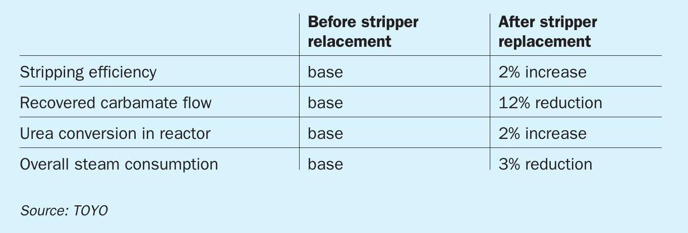
The new stripper was installed in 2018 at the site and the initial start-up operation proceeded smoothly. The performance has been very stable owing to the improved design for the internal liquid distribution system. Table 3 summarises the process performance before and after the stripper replacement. The performance of the ACES21® stripper shows not only its stability but also energy savings due to its excellent efficiency.
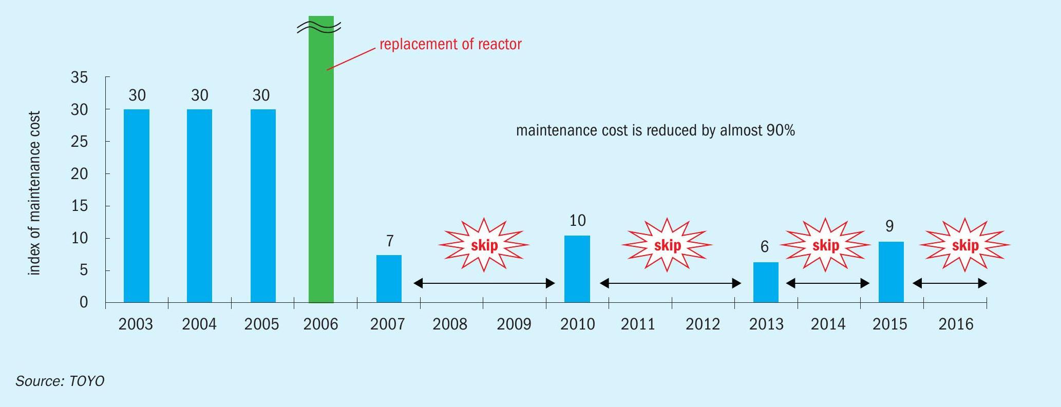
In another example, an old reactor in the total recycle process was replaced with a new one in Japan. The lining material of the old reactor was titanium and the plant owner had struggled to repair the lining defect when it leaked which had occurred frequently. Therefore, the plant owner decided to replace it with a new one lined with DP28W™ ; the intention was to operate the new reactor under the same operating conditions as the existing one (i.e., 250 bar, 200°C). These operating conditions are severe for any material because titanium requires little passivation air even at high temperatures. Nevertheless, it is notable that the actual corrosion rate of DP28W™ has been actually far lower than titanium. The new reactor fabricated with DP28W™ has been in service since 2006 and the plant owner has reduced its maintenance cost drastically by 90% as shown in Fig. 6. Maintenance activity during each turnaround has been mainly visual inspection only and to date there have been no major repairs caused by the material.
Other modern technologies
TOYO also offers various other modern technologies to assist or enhance operability/maintainability for the modernisation of existing urea plants as summarised below.
Online leak detection system
TOYO has developed an online leak detection system for detecting leaking from the lining plate of urea synthesis equipment. This system has the advantage of being able to detect tiny amounts of leakage and to identify the location of defects before the damage becomes severe, which contributes to making maintenance work easier, and increases the reliability of the urea plant. It can be installed for existing and/ or the renewal of urea synthesis equipment to enhance reliability.
Online process condensate analyser
Process condensate is the largest by-product of the urea production process and its quality control is essential for enabling it to be used as boiler feed water make-up. However, a conventional conductivity meter, which is typically installed in existing urea plants, does not show the level of urea content because urea is not an electrolyte in aqueous solution. Therefore, TOYO and Mitsui Chemicals Inc. (MCI) have developed a proprietary online process condensate analyser for the treated process condensate, which analyses not only ammonia but also urea continuously in real time in the range from 1 ppm to hundreds of ppm. As the TOYO-MCI online urea analyser is simply configured and does not require any chemicals and reagents, its initial and running costs are low. Installation of this online analyser improves quality control around the clock for existing plant owners.
Advanced process controller (APC)
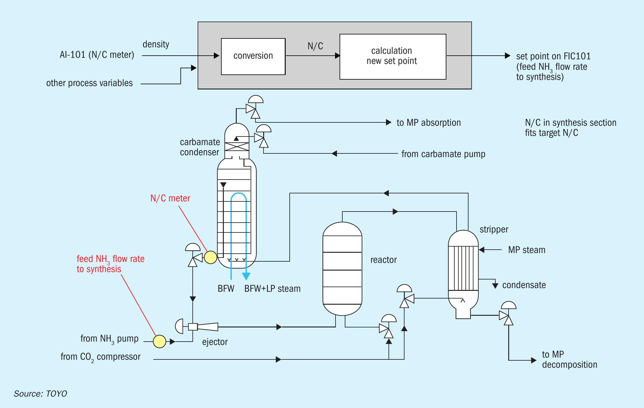
Conventionally, the N/C ratio (NH3 to CO2 molar ratio) of synthesis solution is obtained by laboratory analysis with results delayed be a few hours after taking the sample. Plant operators need to control the N/C ratio by monitoring the conditions of the synthesis section and periodic but non-real-time laboratory analysis results of the synthesis solution. In other words, plant operators have had to change set points of flow controllers for ammonia feed to the synthesis section when operators think it necessary based on their experiences. TOYO’s APC system offers real-time monitoring of the N/C ratio of the synthesis solution with multi-variable control, as shown in Fig. 7; it enables savings in energy consumption, i.e., maximum CO2 conversion can be realised by regulating the optimum N/C ratio in the synthesis section at the optimal point.
DX-PLANT®
In 2016, TOYO launched a digital transformation service named DX-PLANT® in the field of chemical and industrial plants by leveraging IoT and big data analysis technology. Through the development of DX-PLANT® , TOYO has provided unique solutions for the maximum benefit of plant owners. TOYO takes pride in realising the veritable “digital twin” of a real plant by DX-PLANT® and deployment of this service to existing urea plants will contribute to the improved opex and reduction of maintenance costs incurred by plant owners.
Advanced online corrosion monitoring (AOCM™ )
Corrosion monitoring of high-pressure equipment and piping in the urea synthesis loop on a real-time basis is beneficial for plant owners not only in establishing optimised inspection plans but also in enabling reliable operation. Assessing the real-time condition of stainless steels exposed to ammonium carbamate is particularly challenging. TOYO developed AOCM™ (advanced online corrosion monitoring) utilising ultrasonic testing sensors, providing a solution that predicts the condition of equipment and piping (see Nitrogen+Syngas March-April 2021).