Nitrogen+Syngas 380 Nov-Dec 2022
30 November 2022
Decarbonisation of ammonia and methanol
DECARBONISATION
Decarbonisation of ammonia and methanol
Industry focus on technologies to reduce the carbon intensity of ammonia and methanol production has been intensifying. In this article thyssenkrupp Uhde, Proton Ventures, Toyo Engineering Corporation, Stamicarbon, BD Energy Systems and KBR report on some of their latest technology developments towards decarbonisation.
THYSSENKRUPP UHDE
Clean energy based on fossil fuels – blue ammonia solutions
This article introduces the blue ammonia process and technology as a method based on natural gas or other fossil resources with avoidance or reduction of CO2 emissions. Blue ammonia options for new plants and the retrofit of existing plants from grey to blue are presented.
Blue ammonia is attracting more and more attention as, in addition to traditional ammonia demand, there is an emerging additional market for ammonia as an energy and hydrogen carrier. After shipment of ammonia as energy carrier, hydrogen can be released by the cracking of ammonia at the final destination. Blue ammonia technology plays an important role in the transition phase from grey to green ammonia providing the required additional capacity.
Challenges and potential in ammonia production
Ammonia has a worldwide production of roughly 180 million t/a. 80% is used for fertilizer production, and 20% is used for other applications. Around 20 million tonnes are traded and the infrastructure for that is well established.
To date, the prime interest in ammonia has been for its nitrogen content for the production of nitrogen fertilizers. The other element in ammonia however, hydrogen, is the base chemical of the future, replacing oil and gas.
Hydrogen can be easily produced by using renewable energy via water electrolysis, completely free of carbon dioxide emissions. It allows us to store and transport renewable energy and use the hydrogen for a variety of industry sectors.
However, in this vision there are a number of issues that need to be addressed, such as:
- building up a renewable energy infrastructure;
- intercontinental transportation of hydrogen.
Building up a renewable energy infrastructure is the basis for “green” development. However, it will take time to increase the capacity, time which is not available because action is needed now along with social, political and commercial drivers such as:
- increasing CO2 taxes;
- shrinking renewable energy costs;
- new greenhouse gas reduction targets;
- and finally social pressure.
Therefore, despite all movements to green products and processes blue and green products will co-exist, with the focus on blue products in the transition phase. Blue ammonia will be primarily installed where gas is available at relatively low cost.
The other big issue is intercontinental energy transportation. For liquid hydrogen transportation, hydrogen losses and high power consumption for cooling are critical. In addition, there is no infrastructure for long distance shipping available. That’s where ammonia comes into play: It is easy to transport, it has a higher energy density than hydrogen, and global trade is already established. For this reason, ammonia is considered as the most important energy carrier to be globally traded in the future.
Options for reduction of CO2 emissions
Basically, there are two alternative processes for the production of hydrogen from natural gas:
- First, there is steam methane reforming (SMR), where reforming of natural gas takes place inside catalyst-filled tubes, and the heat to drive the reaction is supplied by combustion of gas in a furnace box and heat transfer into the tubes. The flue gas from the furnace is used to preheat the inlet streams and to superheat steam.
- The alternative process is autothermal reforming, where the necessary heat for reforming is supplied by combustion of a portion of the feedstock inside the process vessel. A separate fired heater is utilised to preheat the inlet streams of the autothermal reformer (ATR).
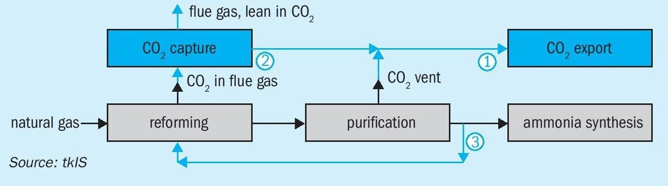
In both concepts there are two CO2 emission points:
- The first emission point is in the reforming section, consisting of the reformer flue gas or the flue gas from fired heater. These streams usually contain only a small fraction of CO2 , the rest is mostly nitrogen, residual oxygen, water vapour, and other impurities.
- The second emission point is in the purification section of the process, where the CO2 is separated from the process gas. This stream is much larger, usually with a CO2 purity of more than 99%. It is this stream, therefore, that is often used for urea production.
At both emission points the CO2 is available at low pressure.
The CO2 emission can be reduced by capturing the CO2 and sending it to a sink. If the CO2 emission is largely reduced, the ammonia is called “blue ammonia”, but there is no unique definition of this term. In principle, two options exist:
- Carbon capture and utilisation, CCU: Using CO2 for downstream applications by production of other sustainable products and thus permanently avoiding its emission into the atmosphere. Unfortunately, not many possibilities exist.
- Carbon capture and sequestration, CCS: Compressing the CO2 and storing it permanently underground in a suitable geological formation.
The overall emission for SMR and ATR is similar (around 1.7 t CO2 per t NH3 for a typical modern plant), but the split of the CO2 emissions between the reforming section and the process differs.
When avoiding CO2 emissions one can define three cases with different degrees of emission reduction, as illustrated in Fig. 1:
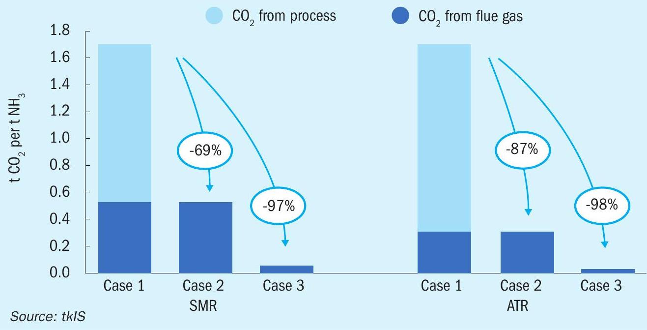
- Case 1/base case: No reduction of emission, two emission points as listed above.
- Case 2: Carbon capture and export (either CCU or CCS) of the CO2 from the purification section of the process. CO2 removal is already provided as part of the standard ammonia process. Therefore, the export of CO2 can be accomplished with low effort by providing an additional export blower or compressor for downstream use. In this way, in the SMR case, the CO2 emission can be reduced by almost 70%, and even more in the ATR version.
- Case 3: Case 2 plus CCU or CCS of the CO2 from flue gas. For this option more effort is required because first a unit for removal of CO2 from the flue gas has to be provided in order to be able to send the CO2 to the export compressor or blower as in Case 2. Technologies for CO2 removal from flue gas are available from thyssenkrupp Uhde and others. 90% removal of the CO2 from flue gas is reported as a typical figure, giving a total CO2 emission reduction of 98%, however, this figure can be increased if desired.
For ATR, Uhde offers an alternative and more cost-effective process to reduce the CO2 emission further than the figures shown for Case 2. The fired heater is provided with hydrogen-rich fuel gas which is diverted from the process (pre combustion solution). This increases the size of the front end but avoids the installation of an additional flue gas scrubbing unit (post combustion solution).
In any case, for the application of ammonia as an energy carrier the demand will be so high that only large ammonia plants will make sense, and for those there is a cost advantage for an ATR plant over a steam reformer plant.
Retrofits of existing plants
Existing plants can be retrofitted to lower their CO2 emission. As shown in Fig. 2 they also possess the same two CO2 emission points as described above.
Many of the existing plants in the fertilizer industry use the process CO2 for urea production. That means, Case 2 (as defined above) is not an option for them. Urea production for fertilizer does not qualify as CCU because the CO2 is only temporarily bound in the urea molecule. It is released to the atmosphere as soon as urea is applied to the field and decomposes.
Case 3 is an option. A CO2 recovery unit can be retrofitted if a destination for the CO2 can be found. Only certain types of geology permit the permanent storage of CO2. Further, it has to be considered that the cost of CO2 sequestration infrastructure is far higher than the that of the equipment for capturing and exporting the CO2.
Summary
There is an emerging additional market for ammonia as an energy and hydrogen carrier. Blue ammonia will play an important role in the transition phase. The ammonia process has two CO2 emission points: While capture from the process gas is standard, capture from flue gas is relatively new, but technologies are available.
For new blue ammonia plants, Uhde offers an optimised and cost-effective process, making use of autothermal reforming (ATR) allowing for more than 90% emission reduction without the need for an additional flue gas CO2 removal unit.
Existing ammonia plants can be retrofitted with a unit to recover CO2 from flue gas in order to lower the CO2 emission and to lower the CO2 footprint of its products which can lead to a competitive advantage.
——————————————————————————————————————————————PROTON VENTURES
Providing engineering solutions for the ammonia economy

Proton Ventures is an engineering solutions provider in the (green) ammonia industry. The company was founded in 2001 by former CEO Hans Vrijenhoef, who had previously been the plant manager of a now defunct ammonia plant in Rozenburg, The Netherlands. Even in the early days, Hans already had the vision to use ammonia as a zero-carbon fuel and hydrogen carrier. About 20 years later, this vision is taking shape with weekly announcements of green ammonia production plants.
Proton Ventures has its fair share of projects in this emerging landscape. These range from scoping studies, feasibility studies, FEEDs (front end engineering designs), and EPC (engineering, procurement, and construction) projects. One of the distinguishing strengths of Proton Ventures is its technology agnostic approach as system integrator, which allows Proton Ventures to select the most suitable licensors and original equipment suppliers (OEMs) for the specific project.
Green ammonia production
Green ammonia production has been a key focus throughout the two decades of Proton Ventures’ existence. Instead of focusing on world-scale ammonia plants producing up to one million tonnes per annum, Proton Ventures has historically focused on modular ammonia plants with a production capacity in the range 3-60 t/d of ammonia. This allows ammonia plants to be located next to modular electrolysers combined with solar PV and wind capacity. The modular approach allows for improved flexibility of the overall ammonia plant.
Recently, Proton Ventures was selected as the EPC contractor for a 4 t/d green ammonia pilot plant (GAPP), to be built at the OCP Group chemical complex in Jorf Lasfar, Morocco. This pilot facility will consist of both an alkaline electrolyser and a PEM electrolyser for hydrogen production, compressed hydrogen storage, nitrogen purification with a PSA system, and a Haber-Bosch ammonia synthesis loop. Another key aspect of the project is the emulator that can simulate electricity profiles from anywhere around the world. This facility is an important step towards scaling up to large-scale green ammonia facilities. The facility will be operated by the Mohammed VI Polytechnic University, thus producing future engineers who have already had experience and training in the green ammonia industry as part of their formal studies.
In addition, Proton Ventures is active within the TransHydrogen Alliance, which aims to produce ammonia in areas with abundant solar and wind resources, such as Brazil and Morocco, with subsequent transport and cracking of ammonia to hydrogen in Rotterdam, the Netherlands. Here the aim is to produce ammonia at a larger scale, e.g., up to 1 million tonnes per annum. The benefit of the TransHydrogen Alliance is that production and utilisation are coupled, ensuring supply while keeping the system cost as low as possible.
The above projects are mainly based on available technology. However, Proton Ventures also works on innovative solutions for ammonia synthesis, such as novel electrolyser technologies and improves ammonia synthesis technologies. Improving hydrogen production via electrolysis is key, as hydrogen production typically accounts for at least 90% of the energy input for ammonia production. Proton Ventures recently performed a feasibility study with Supercritical and Scottish Power for integrating more energy efficient and high-pressure electrolysers with a Haber-Bosch ammonia synthesis loop. Furthermore, Proton Ventures has aided the development of the Battolyser from a university laboratory to a standalone company. The Battolyser is a combination of an iron-nickel battery and an alkaline type electrolyser. Within the EU project ARENHA, Proton Ventures has also patented a low-pressure ammonia synthesis technology that can significantly improve the single pass conversion.
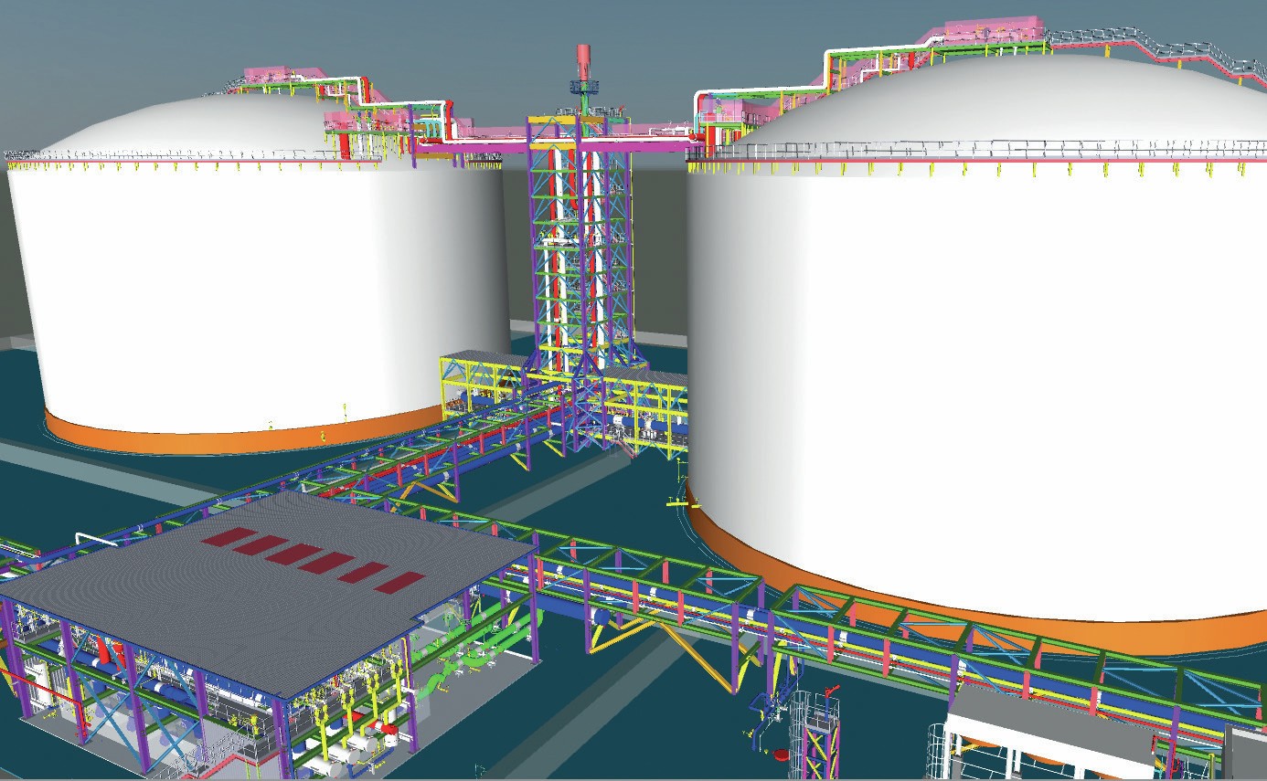
Ammonia storage and handling
Some of the largest projects executed by Proton Ventures are its refrigerated storage tanks in Estonia (BCT) and Bulgaria (Agropolychim), which are among the largest operating ammonia storage tanks in Europe. For example, the two tanks in Estonia each have a capacity for 30 kilotonnes of refrigerated ammonia at -33°C. The tanks are double containment storage tanks complying with modern safety standards. The facilities in Estonia also consist of railcar loading and unloading systems, a marine loading arm facility, and four UAN tanks of 20 kilotonnes each.
The global trade of ammonia is set to expand over the coming decade, as the use of ammonia as a shipping fuel, stationary fuel, and as a hydrogen carrier is taking off. In light of these developments, Proton Ventures has been selected as the EPC contractor for new ammonia storage capacity.
Proton Ventures complies with state-ofthe-art requirements for new ammonia storage tanks, even when these are located in desert areas where temperatures sometimes exceed 50°C. Recently, a FEED+ engineering package was completed for a new ammonia export terminal in the United Arab Emirates. An example is a special main discharge bottom valve for inherent safety. Intermittent flaring and an interconnecting bridge between the two storage tanks with a combined staircase optimise the capital investment, spatial utilisation and simplicity. Furthermore, the refrigeration system design is optimised for hot climate operations and a low operational cost.
Nitrogen oxide emissions
When ammonia is utilised as a fuel or for nitric acid production, nitrogen oxide emissions must be mitigated. NOx emissions are mainly a local issue, causing eutrophication. On the other hand, nitrous oxide (N2 O) emissions cause global warming, with a GWP (global warming potential) equivalent to 298 times that of carbon dioxide.
Nitrogen oxide emissions can be mitigated by reacting nitrogen oxides with ammonia in an SCR (selective catalytic reduction) system, resulting in the production of unharmful atmospheric dinitrogen and water. Within the EU, most nitric acid plants are equipped with such SCR systems, nearly eliminating N2 O emissions from these plants. Around the rest of the world, this is not yet standard practice, implying it is low hanging fruit in the global effort to decarbonise.
Proton Ventures was contracted as EPC contractor by Kavala Fertilizers in Greece for DeNOx and N2 O reduction with an SCR system at a nitric acid plant. This DeNOx system saves about twenty thousand tonnes of carbon dioxide equivalent emissions annually, while meeting the most stringent nitrogen oxide emission standards. The SCR system has also eliminated the yellow plume from the nitric acid plant.
Such SCR systems can also be used for ammonia conversion for energy applications, such as gas turbines and maritime engines. In fact, various gas turbines that are currently fed with hydrocarbons, such as natural gas, have already installed an SCR system, thus already handling ammonia onsite.
Hydrogen production
As ammonia will become more abundant as an energy vector, its use as a hydrogen carrier is set to increase. Ammonia cracker facilities for hydrogen production are currently being considered in various northern European ports, such as Rotterdam and Wilhelmshaven. Proton Ventures has performed various studies on ammonia cracking for clients and remains active within various research consortia. Centralised ammonia cracker solutions for pure hydrogen production are functionally very similar to natural gas processing plants for hydrogen production. Alternatively, decentralised ammonia cracker solutions are currently being developed, which do not always require full conversion and purification of the hydrogen, thereby improving the energy efficiency of the system and the cost.
To consolidate the solution for ammonia cracking, Proton Ventures is currently building its high-pressure ammonia cracking testing facility at the high-pressure laboratory at the University of Twente, the Netherlands. This is critical to validate the operational performance under industrially relevant conditions, while also allowing to test novel cracker concepts. The next aim is to build a commercial pilot for ammonia cracking, before moving to world-scale hydrogen production facilities. This is necessary, as performance in terms of ammonia feedstock utilisation is key for the cost of produced hydrogen. The ammonia feedstock cost can account for over 90% of the total levelised cost of hydrogen from ammonia cracking. Thus, ensuring minimal ammonia feedstock utilisation is paramount.
Leading by example
The ammonia economy will likely become a reality soon. Various decarbonisation projects for existing ammonia plants have already been realised, with newbuilt green ammonia plants under construction. Various consortia are commercialising ammonia energy solutions.
Proton Ventures has been at the forefront of these discussions with the initiation of the NH3 Event in 2017, which was the first European conference focused on low carbon ammonia production, as well as its utilisation as low carbon fertilizer, zero-carbon fuel, and hydrogen carrier. The conference boasts a strong industrial presence, as well as various excellent academic speakers. On the 8th and 9th of June 2023, the NH3 event will be held for the sixth time, returning to its iconic venue: Diergaarde Blijdorp in Rotterdam, the Netherlands.
Twenty years ago, even five years ago, few believed in ammonia as an energy carrier. Throughout its two decades of existence, Proton Ventures has established itself as an engineering solutions expert in the green ammonia landscape. With the same passion, the team continues to serve its customers with ammonia solutions.
——————————————————————————————————————————————-TOYO ENGINEERING CORPORATION (TOYO)
TOYO expands into clean and renewable energy
Toyo Engineering Corporation (TOYO) is a leading international engineering contractor and is expanding its business field to clean and renewable energy towards the realisation of a carbon-free society. In the 1960s, TOYO had its own ammonia process and had licenced it to customers. However, in 1968, based on detailed investigations of a large-scale ammonia plant design, TOYO decided to have a general license agreement with KBR, the global leading ammonia process licensor. In 1969, TOYO built and commissioned its first 1,000 t/d ammonia plant by integrating its own experience and knowhow in designing ammonia plants with the KBR process. To date, TOYO’s experience in ammonia plant projects, including plants based on its own and KBR processes, amounts to 86 projects.
Conventionally, ammonia has been produced from fossil fuels such as natural gas, and most of it has been used for the purpose of chemical fertilizers. In response to the global trend toward carbon neutrality, in recent years ammonia, which burns CO2 -free, has been attracting attention as a new fuel that supports energy security. In addition to expanding the use of ammonia as a low-emission fuel, there is a demand to develop a low-carbon ammonia process.
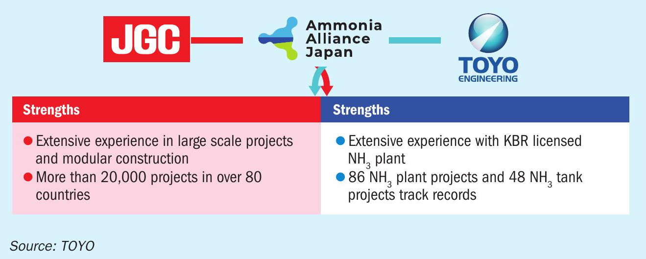
Responding to this movement, JGC Holdings Corporation (JGC), a global engineering company headquartered in Yokohama, Japan, and TOYO signed an alliance agreement on 26th April 2022 with the aim of speedily demonstrating to ammonia fuel business operators enhanced proposal capabilities and competitiveness by combining the JGC’s extensive record of constructing process plants in regions such as Australia and the Middle East with the TOYO’s extensive track record and technical expertise in ammonia production plants. This agreement covers all activities from integrating efforts from the conceptual stage to EPC. Through the expanded use of ammonia fuel, the two groups will contribute to the realisation of a decarbonised society.
Ammonia Alliance Japan
As mentioned above, JGC and TOYO formed an alliance named Ammonia Alliance Japan (AAJ) in April 2022 to realise a zero-carbon society by utilising ammonia as a fuel (Fig. 1).
In October 2020, the Japanese government declared its goal of realising carbon neutrality by 2050. Ammonia fuel shows promise as a decarbonised fuel for power generation, marine transportation, etc. The government has therefore set expanded implementation targets of 3 million tonnes per year as of 2030 and 30 million tonnes per year as of 2050. Accordingly, various companies and organisations both in Japan and overseas have launched initiatives aimed at the manufacturing, transport and use of ammonia fuel.
An alignment of the Japanese government and companies is expected to play a key role in the ammonia fuel business in the future. JGC and TOYO will jointly pursue business operations and project execution related to the evaluation, planning, engineering, procurement and construction of ammonia fuel manufacturing-related facilities around the world, including for overseas companies, and contribute to the future of ammonia fuel.
With the aim to establish a supply chain for ammonia, AAJ, as a global leading engineering contractor, is offering the following solutions with the goal of achieving a decarbonised society:
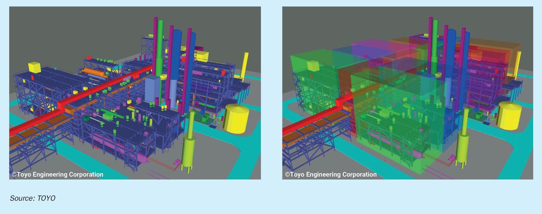
- Reduce construction risk by modularisation
- A 3,000 t/d 3D model and construction basis of proven design has been developed
- Ready to deliver based on deep experience and study
- Benefit from economies of scale by enlarging plant capacity
- Offering a design of 6,000 t/d ammonia production plant with single equipment throughout the flowsheet
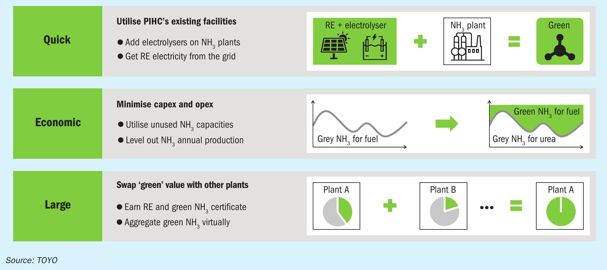
- Ready for front-end engineering design (FEED) l Maximise quality, control and delivery (QCD) level by leveraging the existing facility
- Connect electrolyser and utilise unused production capacity
- Earn “Renewable Energy (RE) & Green Ammonia Certificate” and swap with other plants
Low-carbon ammonia
Conventional ammonia produced from fossil fuels such as natural gas is called “grey ammonia”, while low-carbon ammonia, in which CO2 emissions are reduced in the production process are often referred to as “blue ammonia” and “green ammonia”, depending on the production process and the degree of reduction in CO2 emissions. In this article, blue ammonia is defined as ammonia produced from fossil fuels where the CO2 emissions generated in the production process are sequestered by carbon capture and storage (CCS), carbon capture and utilisation (CCU), or enhanced oil recovery (EOR). Green ammonia is defined as the ammonia synthesised from hydrogen produced by water electrolysis using renewable energy, such as solar, wind, hydro, geothermal, and biomass power.
Fig. 2 shows a simplified process flow diagram and chart showing the production forecast for grey, blue and green ammonia up to 2050.
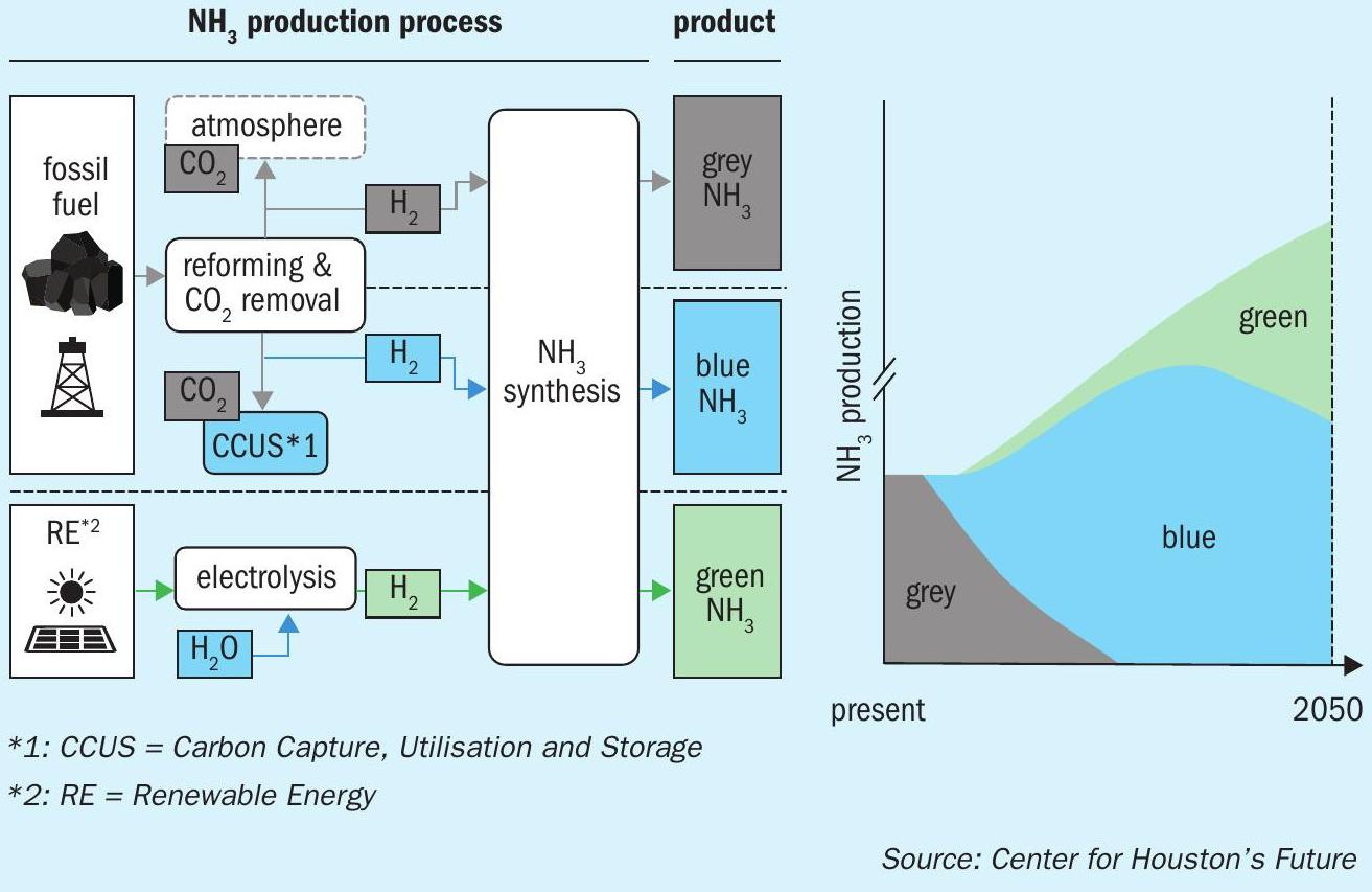
As mentioned before, blue ammonia is a kind of derivative of grey ammonia, still using the conventional steam reforming process but with added CCS or CCU. The hydrogen production for green ammonia, on the other hand, replaces the conventional steam reforming process with electrolysis using renewable electricity, which has a relatively high cost to split water into hydrogen and oxygen. In addition, green ammonia still has several other issues that need to be resolved, for example:
- the energy efficiency of electrolysis is only 70 to 80%; and
- renewable power sources such as solar and wind fluctuate which adds to ammonia production costs.
Blue ammonia is able to cost-effectively supply the large volumes of low-carbon ammonia required to fulfil the new demand for clean fuel in the short term, and it is expected that the large-scale value chain from the Middle East and/or North America to Asia will be built. For green ammonia, on the other hand, local small-scale value chains will be built first in regions such as Europe. After 2030, green ammonia production, for instance in the Middle East, will be increased, where solar generated power is low, and green ammonia will be exported.
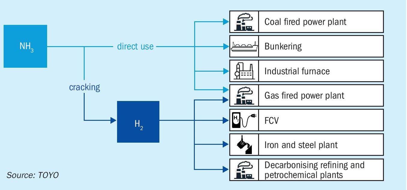
Ammonia can be used in many sectors and for many different purposes. To date, it has mainly been utilised in the field of nitrogen fertilizer. However, there is current interest in ammonia being utilised as a fuel directly for coal-fired power plants, bunkering, industry furnace or gas-fired power plants, or used indirectly as a hydrogen resource, which is produced by ammonia cracking technology, for gas fired power plants, fuel cell vehicles (FCV) or iron and steel plants (see Fig. 3).
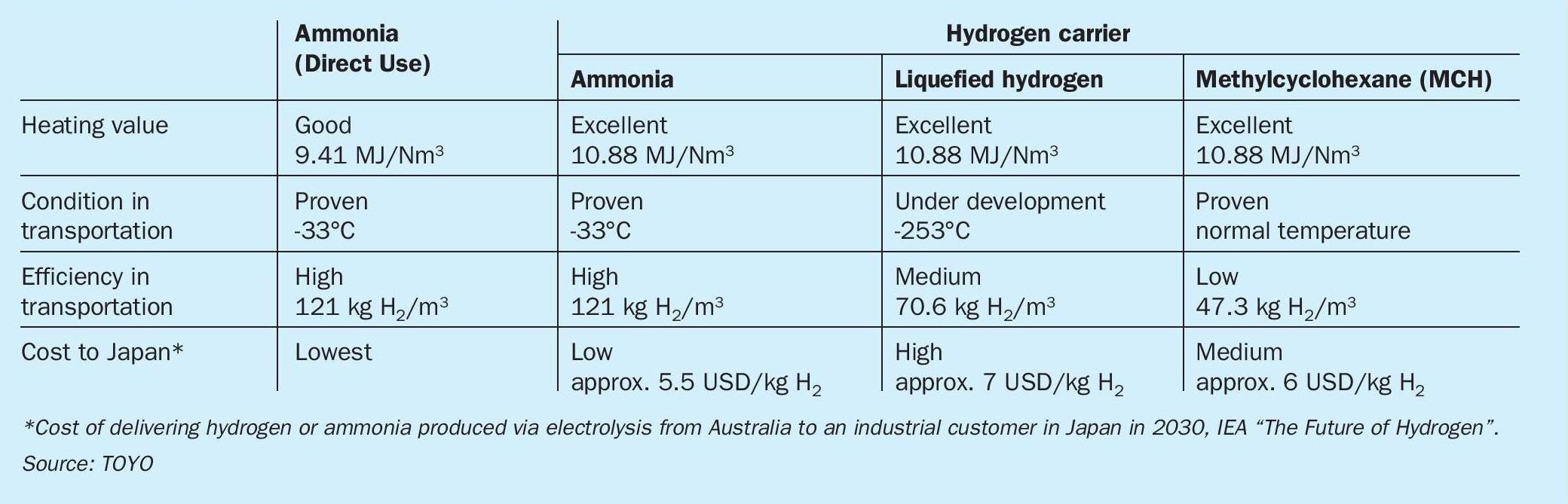
The infrastructure for ammonia transportation, such as marine transportation, land transportation and storage, already exists and is in commercial operation. In contrast, liquefied hydrogen is extremely expensive to produce and transport as it requires cooling to a very low cryogenic temperature, is challenging to contain and lacks the required transport infrastructure. In the case of methylcyclohexane (MCH), which is a hydrogen carrier composed of liquid made by the chemical reaction of hydrogen to toluene, it can be used in the existing petroleum infrastructure because of the liquid phase with petroleum-like characteristics. However, its costs are higher than ammonia since much larger volumes of material need to be transported per unit of hydrogen delivered. This is summarised in Table 1.
Blue ammonia process
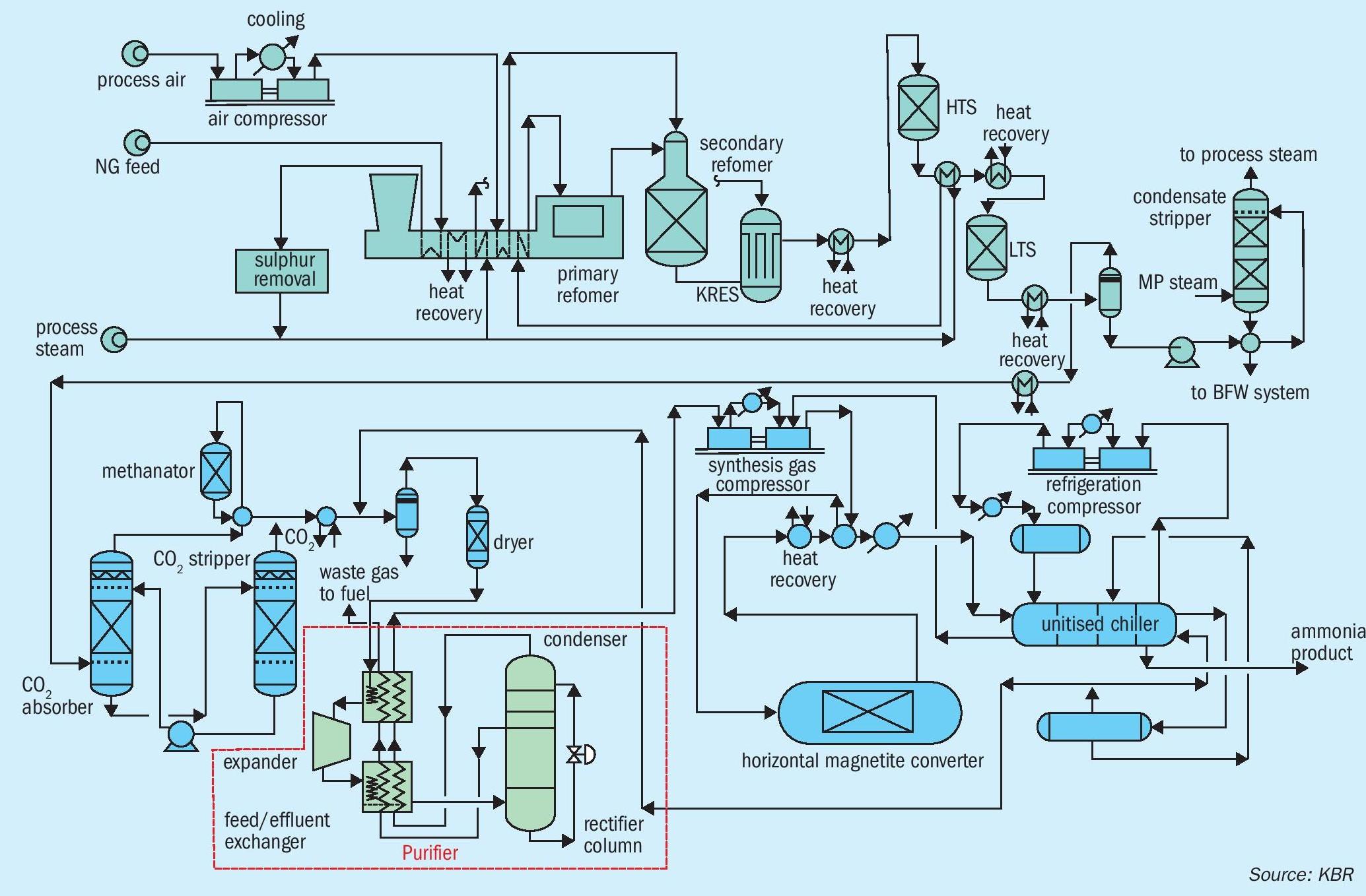
The blue ammonia process consists of the conventional ammonia production facilities and the additional system for CCS or CCU. Although it is more costly than a conventional ammonia process due to the extra facilities, the unit production cost of ammonia can be reduced to a reasonable level by increasing the capacity, due to economies of scale. Currently the largest ammonia plant licensed by KBR with a single converter (and all other equipment) is operating at 3,000 t/d; KBR has already completed the design for 6,000 t/d in a single train, named AMMONIA 6000® and has verified all major equipment with vendors. Fig. 4 shows the process flow diagram of the KBR PurifierPlus™ Blue Ammonia process.
Globally, there is currently no common definition for blue ammonia or hydrogen for example the definitions stipulated by several organisations in different regions currently refer to the amount of CO2 emission. KBR has an extensive line-up of ammonia processes to meet the CO2 emissions requirements stipulated by any of these definitions. Fig. 5 compares CO2 emission rates for KBR’s ammonia processes: (I) conventional steam methane reformer (SMR) and auto thermal reformer (ATR); (II) KBR Purifier™ ; (III) KBR PurifierPlus™ ; (IV) PurifierPlus™ + H2 recycle; (V) PurifierPlus™ + CO2 removal; and (VI) O2 ATR.
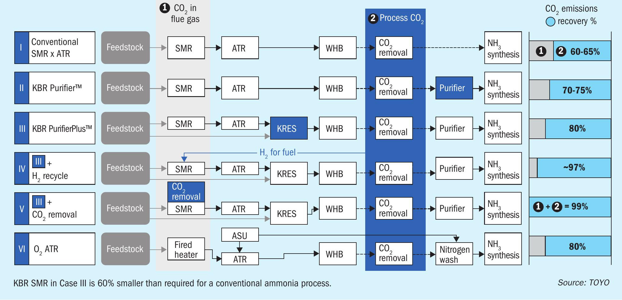
If a CO2 recovery rate of more than 80% is required in line with the latest regulation or a definition at that time, PurifierPlus™ with hydrogen recycling (IV) should be applied. In this process, hydrogen produced in the reforming section is utilised as fuel for the SMR, therefore, the amount of CO2 contained in the flue gas decreases accordingly. The recovery rate will increase up to 97% in this case. A 99% CO2 recovery rate can be achieved by deploying PurifierPlus™ with a small CO2 post combustion carbon capture unit (V). Finally, for the O2 ATR case (VI), the CO2 recovery rate is not 100% because of the associated fired heater that is required. In addition, CO2 emissions from the air separation unit (ASU) should also be considered if renewable energy is not used for the ASU. The CO2 recovery rate for this process is 80%, which is lower than the process using PurifierPlus™ with hydrogen recycling (IV).
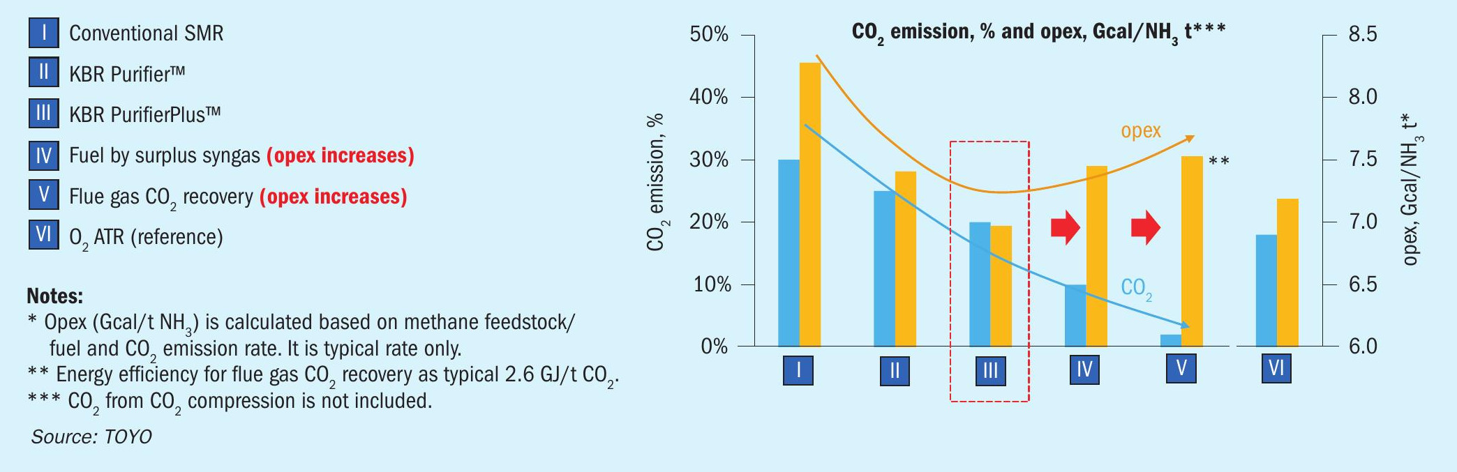
In AAJ’s opinion, blindly chasing CO2 recovery rate is meaningless because the opex to achieve the high recovery rate increases, therefore, it is crucial to consider the balance between opex and a suitable recovery rate. AAJ regards the KBR PurifierPlus™ process (III) as the optimum process option when considering the best balance. In this case, even if the recovery rate needs to increase in the future by due to new regulations, it can be easily achieved by using the hydrogen recycling concept (IV). The balance between CO2 recovery rate and opex is shown in Fig. 6.
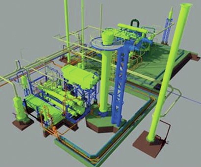
Modularisation
Aiming for ammonia production cost reduction, the modularisation of an ammonia production plant with a capacity of 3,000 t/d has been evaluated (Fig. 7). Modularisation can be a cost-effective approach, especially in regions with high labour costs, such as North America or Australia. In addition, the design of 6,000 MTPD ammonia plant, which might require the modularisation concept, has already been completed and is ready for FEED.
Using a modular assembly enables AAJ to be flexible for the design and provides an engineering solution that facilitates the successful management of EPC, regardless of the project size, scope or location. By fabricating key components in a controlled environment, it is possible to minimise risk, improve quality and stabilise field construction costs, which are typically high and variable. Modularisation also facilitates plant start-up because piecemeal checkouts can be made in a controlled environment. Since modularisation requires careful planning before moving forward and many facets should be considered to make project execution effective, sufficient time should be allocated to assess the various options and to bring all the elements of modularisation together.
AAJ can provide cost certainty to its clients by integrating planning, modularisation know-how, and tightly managing project execution.
Feasibility study for green ammonia
A green ammonia process consists of an ammonia synthesis process with electrolyser facilities, such as water electrolysis, hydrogen gas holders, and storage.
TOYO received an award from the Ministry of Economy, Trade and Industry (METI), Government of Japan and started a feasibility study for green ammonia production in Indonesia, in collaboration with Pupuk Indonesia Holding Company (PIHC), a government enterprise in Indonesia, and Pupuk Iskandar Muda (PIM), a subsidiary company under PIHC.
During the feasibility study, TOYO studied the feasibility of green ammonia production in Indonesia at the existing fertilizer plants owned and operated by PIM, and established a plan for their optimal development, taking into consideration the selection of an appropriate renewable energy power source, effective measures to deal with the fluctuation of renewable energy power supply, etc. TOYO constructed the fertilizer plant for PIM in the 2000s. Utilising its experience and knowledge, TOYO developed a competitive green ammonia production facility by minimising modifications to the existing plant in the most optimum way. In addition, the future decarbonisation of other fertilizer plants under PIHC by applying a similar scheme is also included in the feasibility study (see Fig. 8).
Ammonia is an essential global commodity mainly used for nitrogen fertilizers, and also emerging as a zero-carbon fuel and as a hydrogen carrier for international trade of carbon-free energy. As a technology-orientated contractor, TOYO and JGC have always endeavoured to improve plant efficiency and to reduce plant life cycle costs and will contribute to a carbon-free energy future through the expanded use of blue and green ammonia.
——————————————————————————————————————————————STAMICARBON
Powering ammonia synthesis with renewable energy sources
Climate change can only be beaten if society stops emitting greenhouse gases. To do this, we need to cut emissions from as many sectors as possible and generate the electricity we need using renewable energy sources. As wind and solar energy have inherent fluctuations in availability, integrating renewable energy sources into our grid is a big challenge. Water electrolysis, a patented and proven technology for producing green hydrogen, is the best way to solve this problem by utilising the electrical energy from renewable plants. As hydrogen has a very low energy density, it needs to be stored at high pressures and, on its own, cannot solve many of the world’s challenges.
Ammonia has a higher energy density than even liquid hydrogen. This makes ammonia a good source of bunker/shipping fuel and perfect for green chemicals on an industrial scale, especially with the necessary infrastructure to carry ammonia already in place. With its use in fertilizers, green ammonia is a prime candidate for any country to produce local fertilizers and industrial green chemicals using renewable power and substitute the import.
Stami Green Ammonia in fertilizer production
The Stami Green Ammonia technology differs in the synthesis gas pressure (approximately 300 bar) compared to other conventional ammonia technologies. According to the principle of chemical equilibrium, the synthesis of ammonia is favoured at low temperatures and high pressure due to an exothermic reaction and reduction in the number of moles. The high-pressure ammonia synloop at the heart of the technology has been customised to make the most efficient plant design at a small scale, especially with green feedstock. This setup is more favourable, due to the high purity of the feedstock of the synthesis gas feedstock that has a higher partial pressure of reactants. In addition, there are hardly any inerts present within the process, which means that the conversion per pass of the reactor is higher. This results in a high concentration of ammonia at the outlet of the converter. As a result, purging is also minimised. Due to the phase property of ammonia at high pressure, this design choice allows the majority of ammonia that is synthesised to be condensed with the cooling water, eliminating the need for a multistage refrigerating compressor or multistage chiller where a single-stage refrigeration cycle is sufficient. As a result, the plant operates with a single proven and reliable electric-driven multiservice reciprocating compressor. The minimal equipment needed for plant operations leads to substantial capex savings – an important consideration for small-scale applications. Furthermore, due to the high pressure, ammonia synthesis requires a very small catalyst volume.
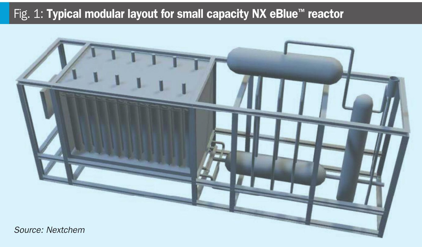
The Stami Green Ammonia technology configuration (Fig. 1), characterised by a modularised approach and thus perfect for small-scale facilities, is the first of its kind, based on proven technology.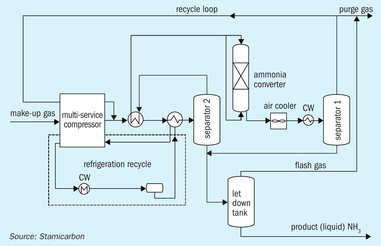
Stamicarbon’s technology package offers a competitive solution for local production on a small scale. It can be applied in combination with its existing (mono-pressure and dual-pressure) nitric acid and urea technologies, moving from grey ammonia to green ammonia-based fertilizers to produce green nitrate fertilizers. In combination with the use of recycled or recovered CO2 , it reduces the carbon intensity of urea fertilizer production.
The technology has four recently commissioned operating references based on natural gas. This is the strongest technology reference in a small-scale range that makes a sound basis for further development of the future small-scale ammonia plant concept.
The technology includes the following key features:
- high capex efficiency;
- strongest reference base with five small-scale plants in operation;
- lean, compact and modularised design;
- high plant reliability thanks to a multiservice reciprocating compressor;
- compliance with the highest environmental standards;
- dedicated operator training simulator available;
- access to digital solutions, such as a process monitoring tool;
- agnostic to upstream water electrolysers and can be integrated with stamicarbon’s nitric acid and urea technologies.
Green ammonia for a greener future
By 2050 the world’s population will grow to nearly 10 billion people. Also, by 2050 hundreds of countries will have to achieve their targets of net-zero emissions aligned with the Paris Agreement. Ammonia acts as a building block for nitrogen fertilizers and plays an important role in providing optimal plant nutrition, yet it is responsible for 1% of the world’s greenhouse gas emissions. Powering ammonia synthesis with renewable energy sources thus becomes a significant step towards more sustainable fertilizer production. The Stami Green Ammonia technology aims to serve as a gateway to carbon-free and futureproof ammonia production and a solution for the production of smart, sustainable, renewable feedstock for nitrogen-based fertilizers.
——————————————————————————————————————————————-BD ENERGY SYSTEMS
New low carbon methanol production approach
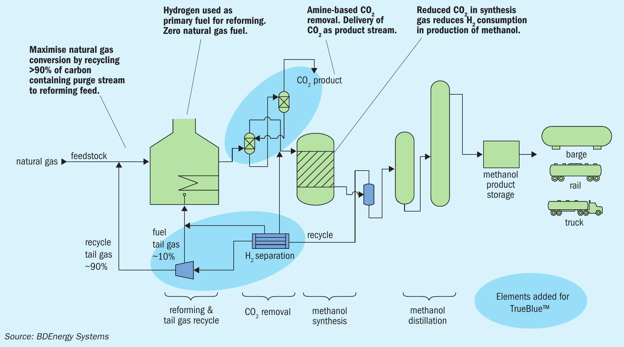
BD Energy Systems LLC introduces TrueBlue Methanol™ , an innovative low carbon emission steam methane reformer (SMR) based methanol production process to the industry. This process utilises proven techniques to achieve greater than 90% reduction in the emission of CO2 from the stack of the SMR furnace while producing methanol with an overall energy consumption that is favourably competitive with even the newest operating SMR-based methanol plants. The TrueBlue™ process can be implemented not only on grassroot and relocated methanol plants but as an upgrade to many existing methanol plants for any natural gas fed process configuration.
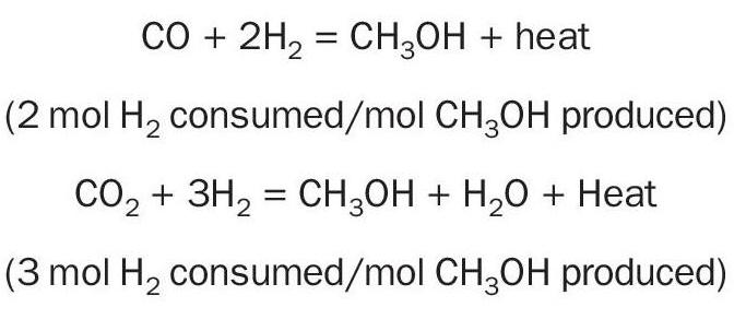
This process delivers a product CO2 stream using an amine-based CO2 removal system placed upstream of the methanol synthesis reactor. Doing so reduces the consumption of hydrogen in the methanol synthesis process, resulting in greater hydrogen availability for SMR fuel. Removal of hydrogen from the synthesis loop purge stream recovers hydrogen for use as SMR fuel, and recompression of the carbon containing tail gas allows recycle of most of the tail gas to the SMR feed. This recycle results in more complete conversion of incoming natural gas feed to synthesis gas and use of hydrogen as the primary fuel effectively reduces SMR stack gas CO2 emissions to a very low level.
This article presents key flowsheet elements of the TrueBlue™ process and an overall performance contrast of the BDE process with conventional natural gas fed SMR-based methanol plants.
Worldwide methanol production1 is largely based on the use of natural gas feed with ~65% of total methanol production based on natural gas, ~35% based on coal, and less than 1% currently based on renewables. Achieving significant reductions in atmospheric CO2 emissions from natural gas-based methanol production is made possible with the approach outlined here.
Conventional SMR-based methanol production
For the purposes of comparison, the “conventional” SMR-based methanol plant is defined in general terms as one having a modern high efficiency SMR, an “isothermal” methanol synthesis reactor, and combustion of the synthesis loop purge gas in the SMR. Overall energy consumption of a conventional SMR-based methanol plant is in the range of 27.0-28.0 million Btu of total energy (LHV basis) per short ton of high purity methanol product. Total energy here is based on total natural gas, feed plus fuel, as well as net electric power import for the methanol plant and associated utility units.
Use of natural gas (96-97% methane) as feed results in the production of more hydrogen than required for methanol synthesis. This excess hydrogen is typically purged from the methanol synthesis loop and burned as fuel in the SMR. This reduces the make-up natural gas fuel required for the SMR; however, required natural gas fuel makeup remains in the 7-8% range in terms of total required heat release. Further, the hydrogen containing purge gas from the methanol synthesis loop also contains methane, carbon monoxide and carbon dioxide. Considering only the SMR fuel, not including fuel to a gas fired boiler or a gas turbine, the emission of CO2 to atmosphere is in the range of 0.35-0.36 weight CO2 /weight methanol product. So, for a 2,000 t/d conventional methanol plant, the SMR stack gas CO2 emissions would be in the range of 700720 t/d (255,500 to 262,800 t/a).
BDE TrueBlue Methanol™ production
The BDE TrueBlue Methanol™ plant design is also SMR-based with several significant additions when compared with the conventional plant. First, the SMR front end includes the use of pre-reforming and convection section reheat of pre-reformer effluent to effectively shift a portion of the required reforming reaction duty from the radiant section to the convection section.
Second, an amine-based CO2 removal system is added immediately upstream of the synthesis gas compressor to reduce the proportion of CO2 feeding to the methanol synthesis reactor. This effectively reduces the quantity of hydrogen consumed in the production of methanol, reducing the amount of reaction water produced, which enables recovery of that hydrogen for use as SMR fuel.
Third, purge gas from the methanol synthesis loop is routed to a pressure swing adsorption (PSA) unit to separate out a major portion of the hydrogen remaining in that stream for use as fuel. The tail gas from the PSA unit, containing CH4 , CO2 , CO, inert components, and unrecovered H2 , is recompressed to allow recycle of approximately 90% of the tail gas back to the SMR feed stream. Approximately 10% of the PSA tail gas is routed to SMR fuel to limit the accumulation of inerts in the synthesis gas. The recovery of hydrogen as described, along with the small PSA tail gas flow are enough to supply all the fuel required for the SMR, reducing the natural gas firing of the SMR to zero. The recycle of approximately 90% of the carbon containing components of the purge achieves more complete conversion of incoming natural gas feed to synthesis gas.
These added elements extract CO2 from the plant as a product stream while reducing the SMR stack gas emissions of CO2 by 90-93% when compared with a conventional plant.
Overall energy consumption of the BDE TrueBlue™ methanol plant remains in the range of 27.0-28.0 million Btu of total energy (LHV basis) per short ton of high purity methanol product. Total energy here is based on total natural gas feed with zero natural gas fuel, as well as net electric power import for the methanol plant and associated utility units.
With the use of hydrogen as the primary fuel and make-up fuel being a portion of the PSA tail gas, there is no need for natural gas fuel firing.
Compared to conventional SMR-based plants, considering only the SMR fuel, not including fuel to a gas fired boiler or a gas turbine, the emission of CO2 to atmosphere is in the range of 0.032-0.035 weight CO2 /weight methanol product. So, for a 2,000 t/d conventional methanol plant, the SMR stack gas CO2 emissions would be in the range of 64-70 t/d (23,400 to 25,600 t/a), and the CO2 product stream is in the range of 636-650 t/d.
The TrueBlue™ process effectively converts the stack CO2 emissions of a conventional plant to a CO2 product stream.
Comparison with alternative carbon capture methods
The BDE TrueBlue Methanol™ production process achieves 90+% reduction in SMR stack CO2 emissions by reducing carbon containing components in the fuel gas through use of “pre-combustion” CO2 removal and recycle of a high percentage of the carbon containing tail gas to the feed. There are other processes that utilise a combination of pre-combustion and post-combustion CO2 capture that can achieve a comparable overall level of CO2 capture. However, the post-combustion capture techniques for low pressure flue gas can be troublesome with respect to degradation of the absorbent solution, the corrosive nature of those solvents, and reduced efficiency of absorption in a low-pressure application.
The elements added for the TrueBlue™ process are well proven, while the SMR design must be designed specifically to accommodate firing of 98% hydrogen fuel, and a higher extent of pre-reforming compared to a conventional SMR-based plant.
Reference
—————————————————————————————————————————————KBR
KBR clean ammonia technologies
The world is facing a massive challenge in the race for decarbonation to combat climate changes and to limit global warming to 1.5°C as per the Paris Agreement. This journey towards net zero in 2050 requires double digit trillion dollars investment in technologies and infrastructure for low carbon fuels and electrification.
Ammonia is predicted to play a major role in this journey, as a clean fuel on its own or as a carrier of hydrogen. The ammonia demand is therefore expected to increase significantly, with CAGR around 4% up to 2050. The majority of this ammonia is expected to be produced via renewable power and electrolysis, often designated green ammonia, but a significant share will be produced via reforming of fossil fuels and carbon capture, often designated blue ammonia.
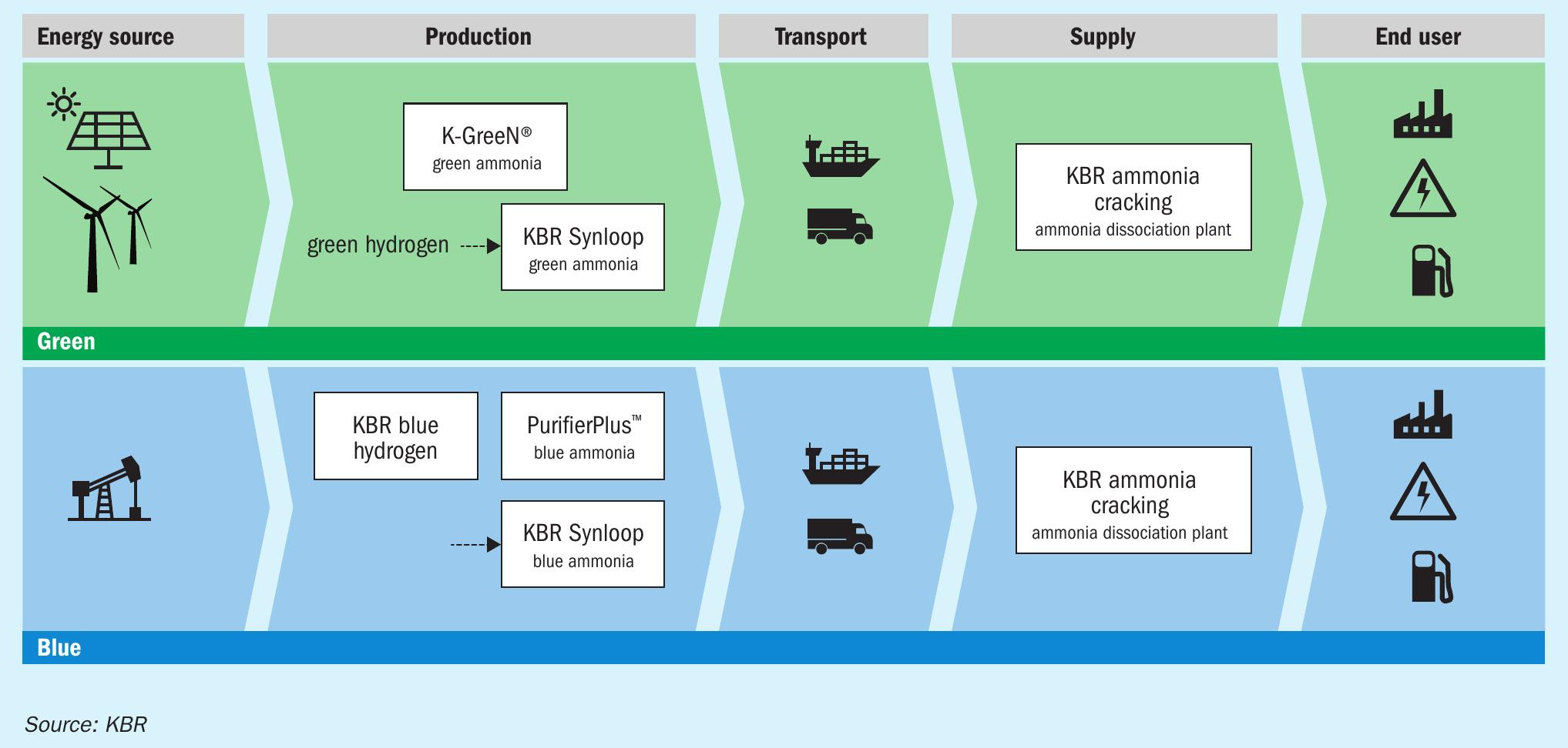
As a technology provider for ammonia technology for more than 75 years, KBR has actively and continuously enhanced the technical features of its ammonia technology. These technical innovations and improvements have enabled owners of KBR-designed ammonia plants to obtain consistently safe, reliable and cost-effective operation. Today, that same proven technology is being applied to deliver the most efficient solutions for blue and green ammonia, hydrogen as well as ammonia cracking (see Fig. 1).
Blue ammonia
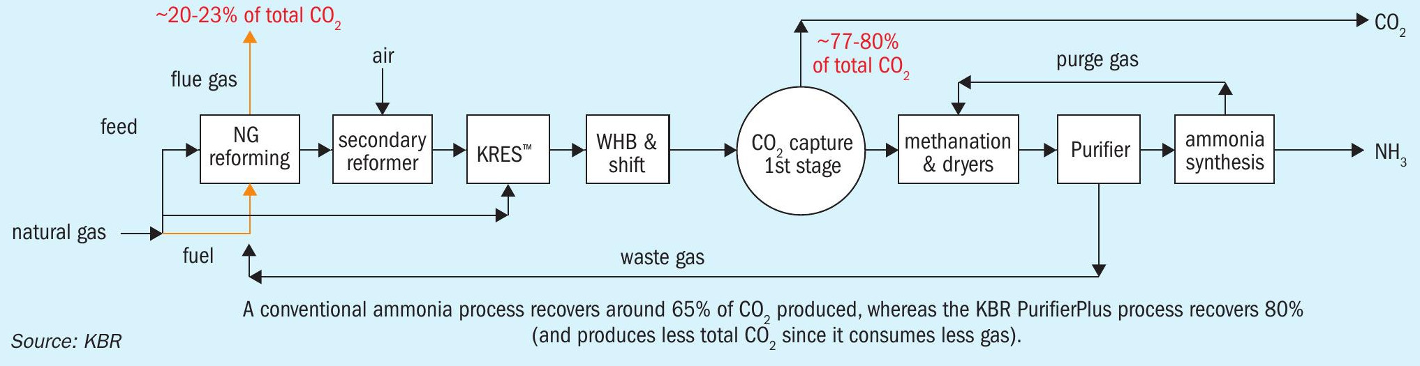
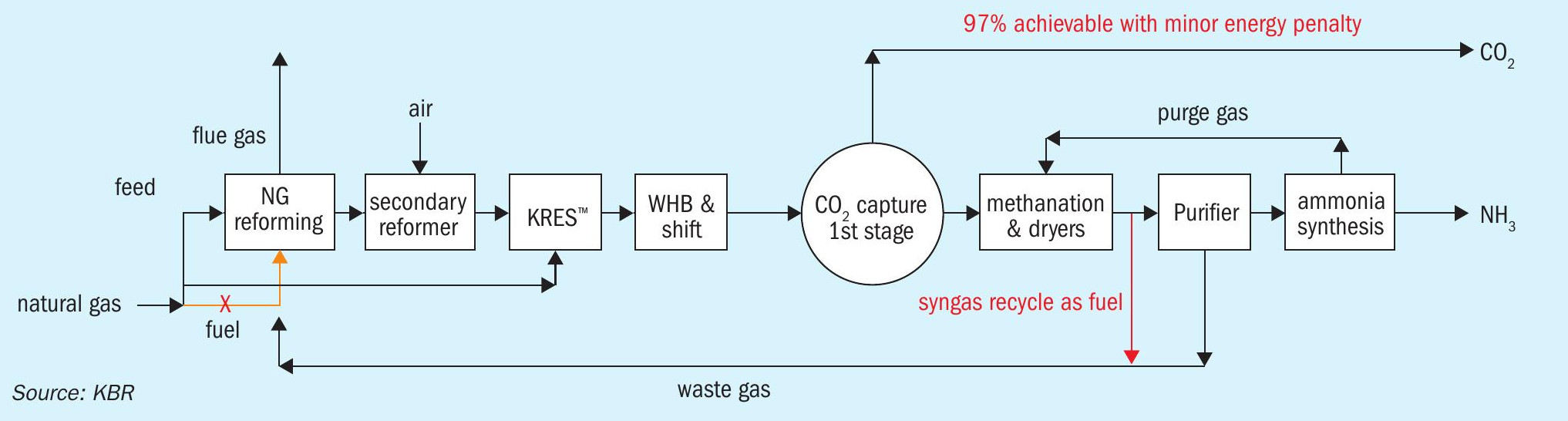
KBR’s blue ammonia process is based on its PurifierPlus™ technology which incorporates KBR’s proven Purifier™ and KRES™ (KBR Reforming Exchanger) technologies to generate ammonia with high energy efficiency, high reliability, low capex, and low opex, all while capturing up to 99% of the unit’s overall CO2 output.
The sources of CO2 in the ammonia unit are from the primary reformer fuel combustion, and from the conversion of natural gas into hydrogen in the process system. To reduce the overall generation of CO2 , the KBR Purifier™ technology allows for mild primary reforming, through the use of excess air in the secondary reformer, which is associated with a reformer radiant duty reduction of 30% in comparison with conventional schemes. When combined with a KRES™ , there is a further reduction in radiant duty of 20-30%, for a total reformer duty reduction of 50-60% versus conventional designs. This radiant duty reduction leads to much lower CO2 generation in the ammonia unit, as well as significantly lower generation of CO2 in the furnace fuel system.
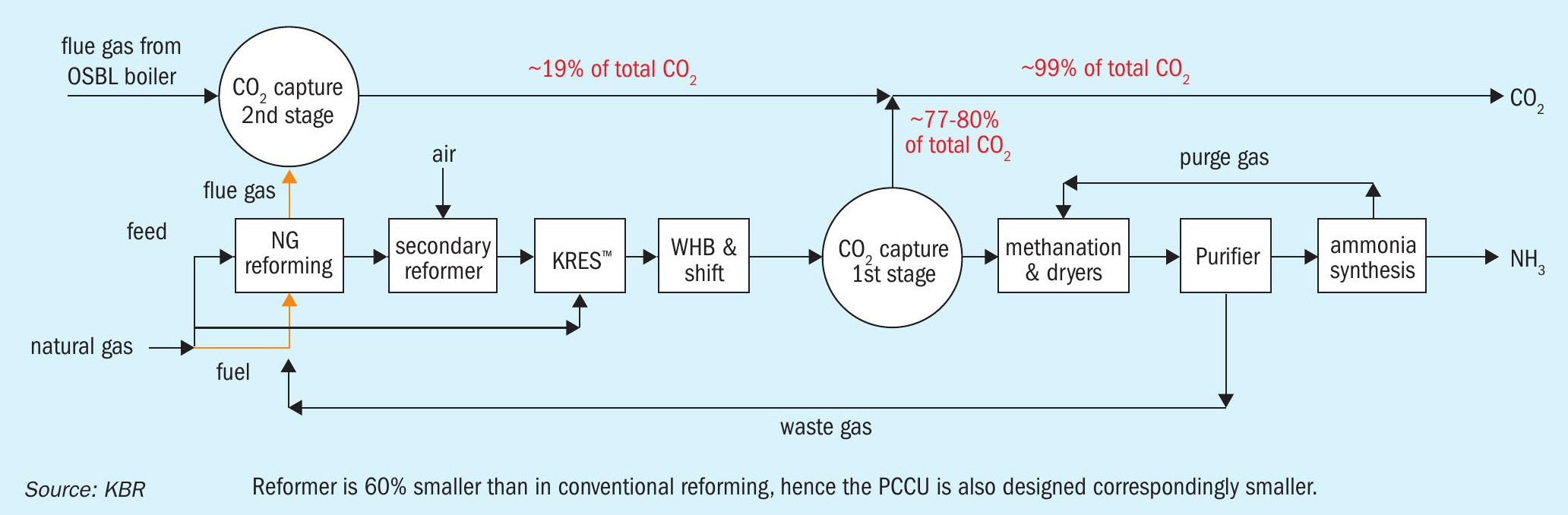
These unique features of the Purifier-Plus™ technology, will allow the recovery of up to 80% of the generated CO2 without any modifications to the PurifierPlus™ process, and this proven technology is therefore an excellent platform for a staged investment that by subsequently applying a syngas recycle as reformer fuel or adding a Post Combustion Capture Unit (PCCU) will be able to increase the CO2 capture up to 97% and 99% respectively.
The basic PurifierPlus™ technology and the two options for either syngas recycle or a PCCU are shown in Figs 2-4.
In all three process schemes, the inherently better chemistry of a SMR-based process vs. that of an oxygen-based process, described via the R number (R number is used to describe the composition of the syngas produced R = H2 -CO2 /CO+CO2 ) leads to the lowest generation of CO2 per tonne of NH3 produced.
In the KBR PurifierPlus™ process, R = ~2.2 whereas in ATR processes R = ~1.85.
The lower the R number, the more CO2 and CO the process will produce which is not advantageous when the desired product is NH3 with no carbon content.
Consequently, the natural gas consumption in the KBR PurifierPlus™ process is lower and coupled with a limited need for OSBL support units, this further reduces the overall CO2 emission when considering the total emission combining scope 1, 2 and 3 of CO2 emissions.
Green ammonia
A global shift from grey ammonia in the direction of green requires a technological response to maintain safe and stable operation of the plants as well as to maximise the ammonia production and to increase revenue for the plant operator. Intermittency and fluctuations of renewable energy generation sources delineate increase of responsiveness and flexibility of both electrolysis systems as well as the ammonia synthesis loop itself.
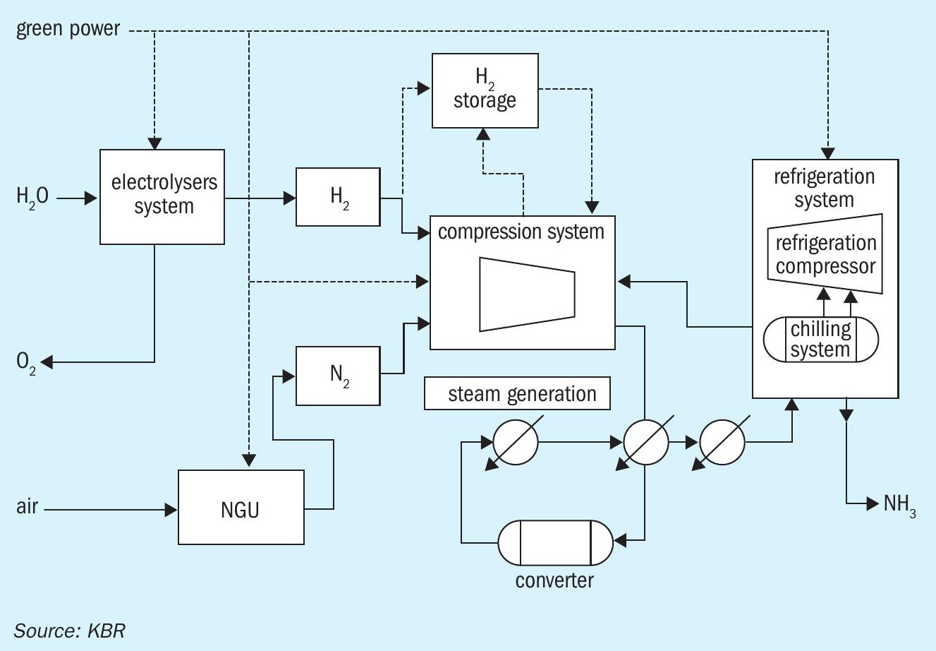
KBR have developed K-GreeN® , a complete solution from renewable energy to green ammonia (Fig. 5). Part of the development comprises technological advantages in the ammonia synthesis loop that allow the plant to be turned down to lower capacities as well as having greater flexibility to ramp it up and down.
Additionally, KBR has developed an advanced process control system for green ammonia that minimises the fluctuations of the process conditions and allows the utilisation of available renewable energy to be maximised. It combines current, forecasted as well as historic weather data with proper management of hydrogen and electricity storage levels. Moreover, it includes electrical grid cooperation and optimises electrical energy sourcing by dynamically responding to variable pricing (e.g., own behind the meter sources, PPA, spot price, etc.). Use of the advanced process control system further stabilises plant operation, minimises mechanical wear of auxiliary equipment, smooths out ramp-up and ramp-down curves and prevents plant outages. This, combined with the most efficient and reliable ammonia technology of KBR, maximises the product output and income for plant operators.
Fig. 6 shows an optimisation case study of the advanced process control system.
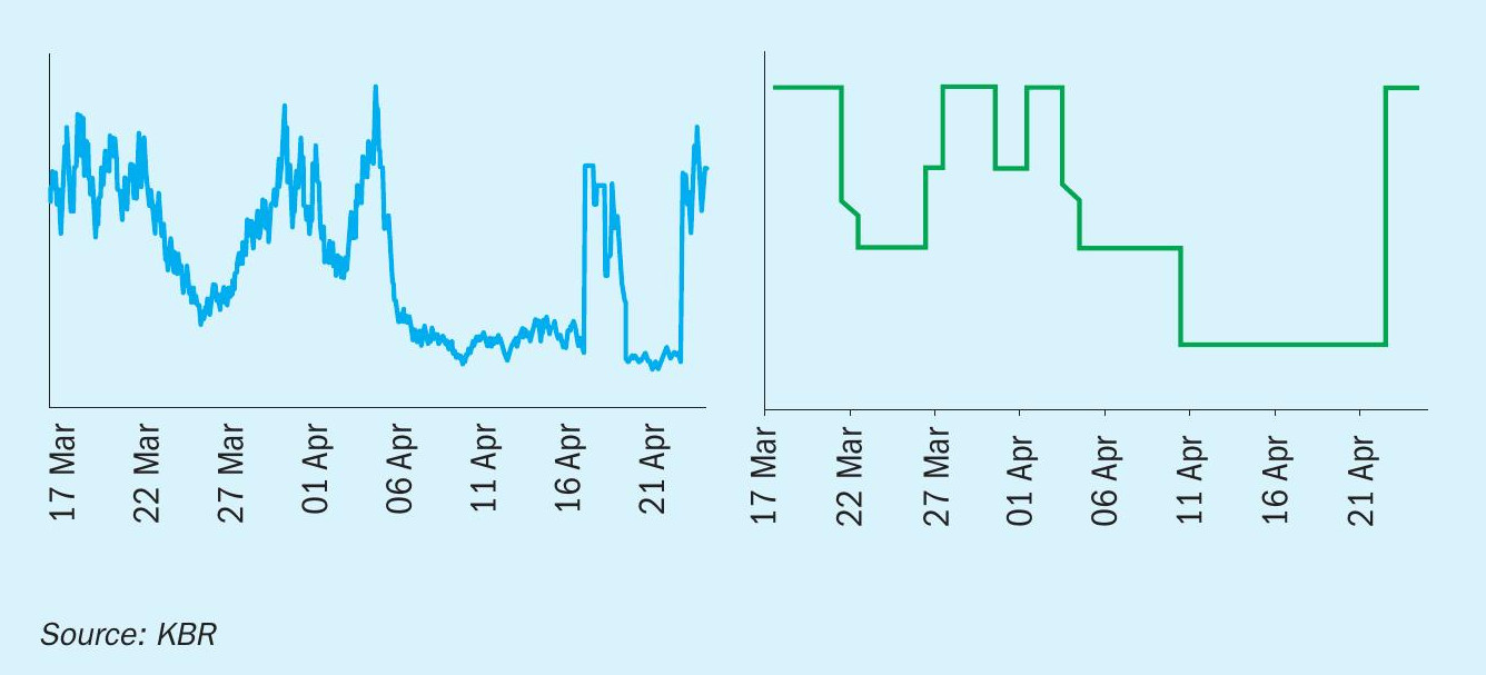
In the left figure a fluctuating energy feed is presented. This is a typical energy profile that can be expected from a renewable energy source. Usually, even if a grid connection is present, it is not enough (or not cost-effective) to maintain the same level of green ammonia production. Furthermore, if grid power is not generated from renewable energy sources, then the ammonia produced is not from a low-carbon source. Some developments are also planned as off-grid plants, where maintaining stable operation would be required without the capability of receiving external support in terms of grid power. KBR advanced process control systems allow the plant to be optimised from the first concept phase making sure that the equipment is properly sized for the specific project and allows the plant to maintain its stable operation throughout the whole period of operation.
Ammonia cracking
Low carbon hydrogen is earmarked as the sustainable fuel of the future while green/ blue ammonia offers a flexible, high energy density solution for storage and distribution, utilising existing and reliable infrastructure. The advent of ammonia cracking technology, dissociating green/blue ammonia back into low carbon hydrogen, completes the missing link in the roadmap to sustainability, enabling the production of low carbon ammonia where the renewable energy or natural gas resources are abundant with the ability to supply low carbon hydrogen in locations with high demand but low availability of natural resources to produce it.
Leveraging on decades of ammonia technology experience, KBR is continuing its pioneering journey with KBR Ammonia Cracking technology, to address customer demand and complete the green ammonia value chain offering. KBR has successfully developed a competitive ammonia cracking technology, high efficiency and able to meet stringent environmental requirements on carbon emissions (whether from blue or green ammonia feedstock), targeting moderate to very large-scale capacity green hydrogen production.
Today, this technology is available in the market serving a different purpose. The installed units are fully electricity driven, very small capacity and operate at equilibrium-favoured conditions (low pressure, high temperature). Whilst these units serve the installed purpose, they are not suitable for what the market is looking for in the energy transition.
As a technology powerhouse with decades of know-how in process design and extensive experience in equipment design, coupled with market proven capability to scale-up and commercialise new technology, KBR can offer different routes for technology scale-up and commercialisation.
Fig. 7 shows a typical simplified block flow diagram for the KBR ammonia cracking unit.
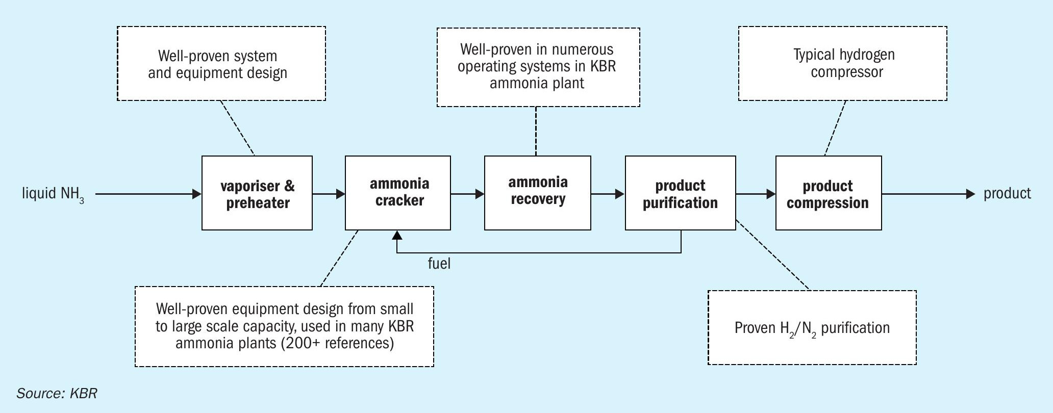
KBR is focusing its developments on the following areas:
- Catalyst: Partner with world-leading catalyst suppliers and consider both conventional proven and novel catalysts.
- Reactor: Use well-proven reactor design using decades of reactor design know-how from successful operation now applied to ammonia cracking application.
- Flow scheme: Fully developed flow-scheme with high energy efficiency and hydrogen yield. The flow scheme is optimised and tailored to client and project specific requirements to minimise the levelised cost of cracked hydrogen production.
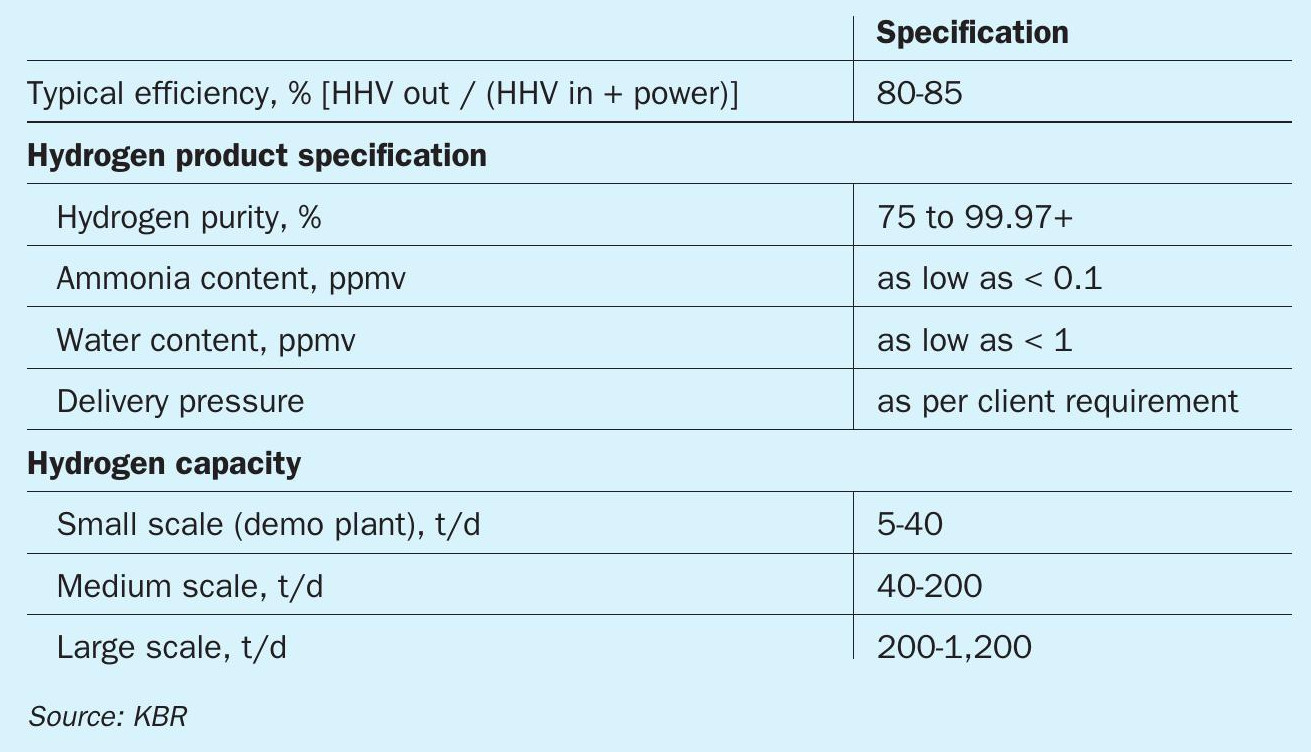
Table 1 outlines the typical performance of the unit.
Flexibility and scale
The first KBR Purifer™ plant was started up in 1966, and since then more than 40 Purifier™ /PurifierPlus™ ammonia plants have been built worldwide, providing a highly optimised and proven platform for blue ammonia projects, with lowest energy consumption (below 6.30 Gcal/t) and highest service/online factors, with up to 6,000 t/d ammonia capacity in a single line layout.
This vast experience has been imbedded in the KBR K-GreeN® solution and contributes to the flexibility and scale offered for green ammonia projects as well.
The unique features of the KBR Purifier™ /PurifierPlus™ process alongside continuous equipment optimisations, also result in low capex independently of whether the carbon capture is done via the scheme in Fig. 3 or Fig. 4, as the two schemes result in the same capex.
KBR clean ammonia technologies provide the platform for a highly competitive levelised cost of ammonia (LCOA), with an unmatched large scale option for completing the hydrogen value chain via KBR ammonia cracking technology.
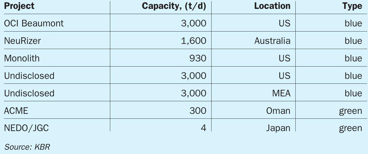
Grassroot clean ammonia projects
KBR is already involved as technology provider for several major blue and green ammonia projects in various stages of project completion. In addition to the list shown in Table 2, KBR is working with multiple clients for earlier stage assessment of both revamp and grass root plants well above the 3,000 t/d capacity.
Revamps
For existing ammonia plants, a significant step towards improved CO2 footprint would naturally require sequestration options or usage of the emitted CO2. Some revamp options could be:
- Existing process CO2 removal unit could be revamped for efficiency and energy improvements.
- A PCCU could be added to the steam reformer.
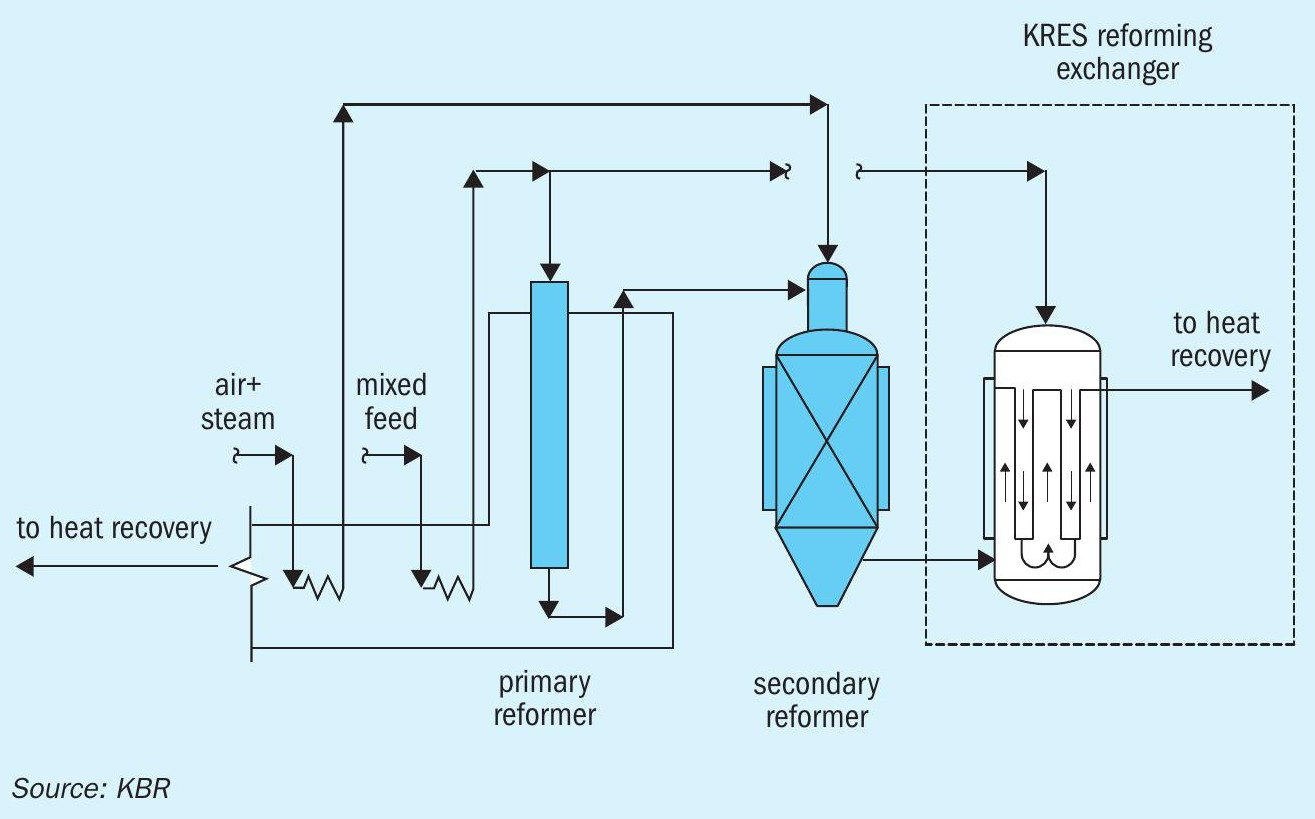
- Natural gas consumption could be lowered by adding a heat exchange reforming unit like KRES™ (Fig. 8) lowering the steam reformer duty with up to 20% and thereby also CO2 emissions from the stack correspondingly.
KBR is working with multiple partners on further advancements in CO2 capture technologies and usage of the CO2 captured. This is vital as advancement in CO2 capture technology and usage thereof, will be the key to lowering the carbon footprint of existing assets that today have no or limited carbon capture.
Commitment to deliver
The motto of KBR is to deliver, and this promise is carried into the space of clean ammonia technologies, delivering already a wide range of solutions through the whole value chain.
KBR is working closely with many partners in the entire value chain leading to a range of low carbon fuels, to ensure that solutions are adapted to meeting the requirements needed, while also strongly committing to providing reliable and efficient new sustainable solutions.