Sulphur 403 Nov-Dec 2022
30 November 2022
Maximising energy efficiency in acid plants
SULPHURIC ACID CATALYSTS
Maximising energy efficiency in acid plants
With energy prices skyrocketing, sulphuric acid plant operators face a heightened challenge to improve plant efficiency. Martin Alvarez from Topsoe discusses how the company’s new high-activity catalyst, VK38+, can help acid plants maximise energy efficiency to secure important economic benefits while simultaneously reducing their carbon footprint.
With geopolitical tensions leading to a sustained increase in electricity prices, improving the energy efficiency of acid plants has become a priority for many sulphuric-acid operators. However, this isn’t a straightforward task since it can require expensive revamps, or the installation of new, advanced heat recovery systems. A cheaper option is to upgrade the catalyst loading using the new potassium-promoted VK38+ catalyst, which was introduced in 2020, to tip the scales in operators’ favour as new operational necessities arise.
Case 1: Increasing steam generation
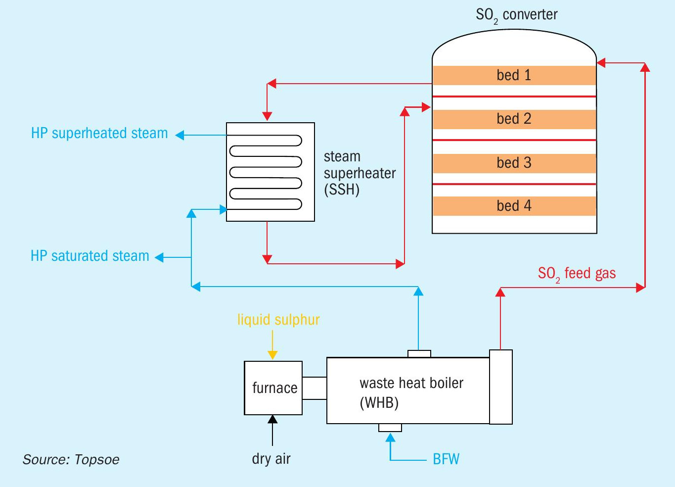
A typical sulphur-burning unit has a steam system designed to recover the heat generated across the various process units; a major portion of the recovered heat originates from the combustion of the molten sulphur into SO2 gas. This SO2 feed gas exits the furnace and is cooled in a waste heat boiler (WHB) to the optimum inlet temperature required for entry into the first bed of the SO2 converter. Once the gas enters the converter, the oxidation of SO2 to SO3 occurs in the different catalyst beds. The conversion process is exothermic, so recovery of as much reaction heat as possible in the interbed coolers, will prove economically attractive. As shown in Fig. 1, the gas exiting bed 1 is typically cooled in a steam superheater, which uses this energy to superheat a portion of the saturated steam produced by the WHB. Since the recovered steam can be used a) to generate electricity in a steam turbine, b) as a heating medium in other parts of the unit, or c) exported to other customers, increasing steam production is often of key importance.
How can VK38+ help to increase steam and acid production?
One of the ways to increase the steam generated in a sulphur-burning plant is by increasing the amount of sulphur that is burnt in the furnace, while maintaining the air flow rate constant. This would be very attractive for most acid producers because it would enable, at the same time, an increase in the production capacity of the unit without increasing the gas volume handled by the plant. However, keeping the airflow unchanged while burning more sulphur will increase the SO2 concentration at the inlet of the SO2 converter. And if the catalyst solution isn’t upgraded, then a stronger gas will inevitably generate higher SO2 emissions. There are two alternatives for utilising stronger feed gas without experiencing such an emission increase. The first is to increase catalyst volume, but free converter space is usually very limited or unavailable altogether. The second alternative is the use of a more active catalyst.
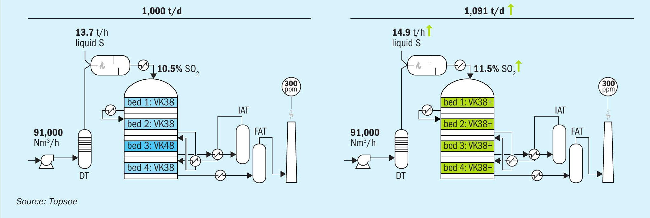
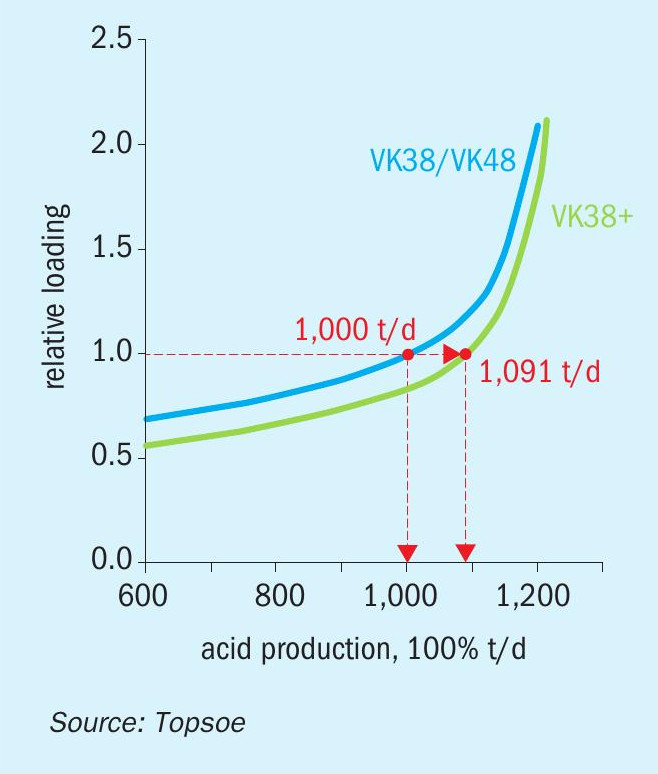
Fig. 2 displays the catalyst volume needed for a sulphur-burning unit to reach a certain level of emissions at different acid production rates. Both curves have been made considering a constant airflow of 91,000 Nm³/h, and the different production capacities have been achieved by increasing the strength of the feed gas. The VK38+ curve remains consistently at the right of the VK38/VK48 curve, showing that a VK38+ solution can, in general, accept stronger gases and higher capacities from the same catalyst volume.
Fig. 3 explains how this concept can be applied to a 1,000 t/d plant operating initially with 10.5% SO2 gas. By switching the catalyst from VK38/VK48 to the same volume of VK38+, the catalytic converter would be able to admit the same feed gas flow at a higher SO2 concentration, keeping the emission level unchanged. The increase in the gas strength from 10.5% to 11.5% will lead to a production increase from the original 1,000 t/d to 1,091 t/d. Using a sulphuric acid price of e117/t, these 91 extra daily tonnes of acid will bring an annual benefit of around e3.50 million.
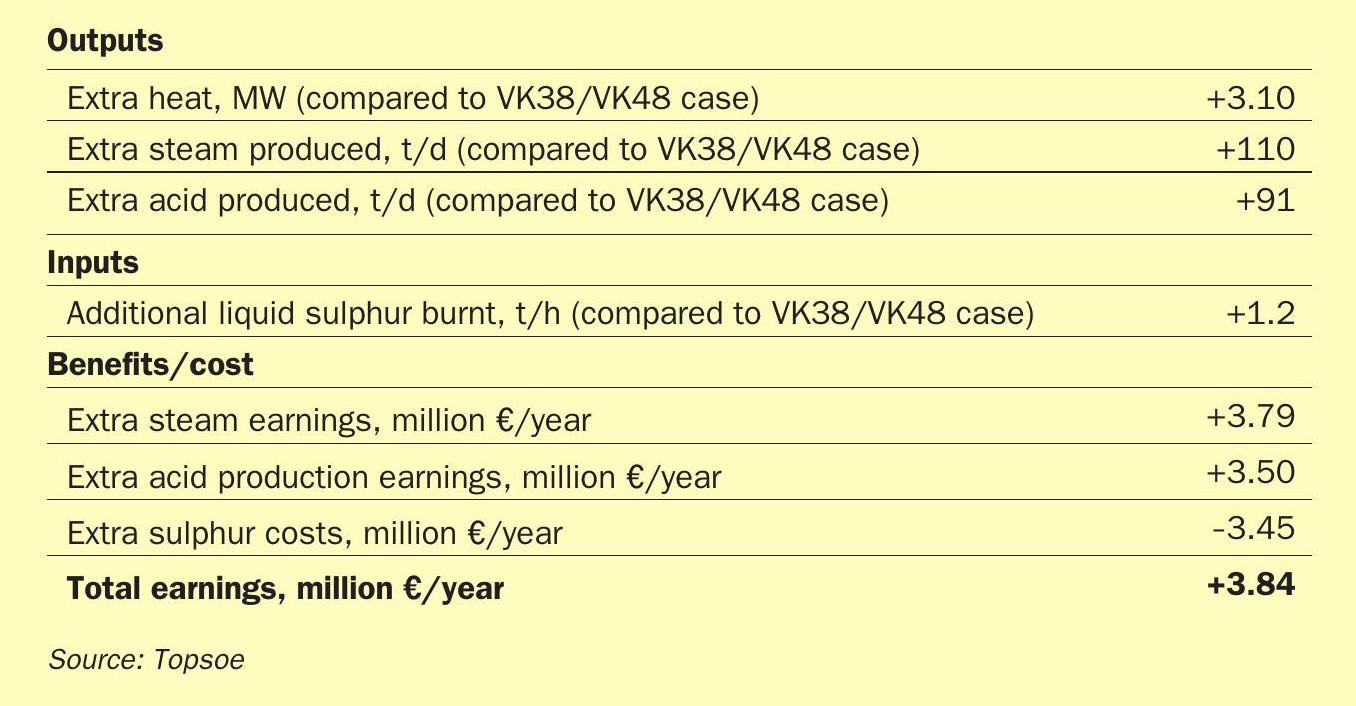
As this increase in the gas strength is achieved by burning more sulphur in the furnace, the sulphur combustion heat increases by around 3.10 MW. Provided that the steam system has thermal capacity available to recover this additional heat, these 3.10 MW are equivalent to an extra HP steam production of approximately +110 t/d. The extra steam production is achieved without increasing the pressure drop of the unit and therefore improving the energy efficiency of the plant.
Using the natural-gas cost of the steam generation, 110 tons of extra steam, delivered daily, would represent around e3.79 million/year, according to the current gas prices at the Dutch TTF (e130/MWh). On the other hand, assuming a liquid sulphur price of e350/t, the additional 1.2 t/h of liquid sulphur that needs to be added to the furnace in order to increase the SO2 strength to 11.5% would have an extra cost of e3.45 million/year.
Overall, after deducting the liquid sulphur costs, the economic benefit of the VK38+ solution would be around e3.84 million/ year. This is summarised in Table 1.
The extra amount of steam generated will result in a carbon emission reduction of approximately 4,500 t/year of CO2 .
Case 2: Reducing the blower’s energy consumption
The power consumption of the blower is another process point to focus on when optimising the energy efficiency of a sulphuric acid plant. There are two ways to reduce the blower’s energy consumption: reducing the feed-gas flow rate or reducing the pressure drop.
How can VK38+ help reduce the gas flowrate without losing production?
Reducing gas flow won’t be a very attractive option, since solely doing so will reduce acid production to the same degree. However, if reduced feed-gas flow is compensated by increased feed-gas strength, acid production can be maintained, even with the plant operating at a lower flow rate.
As discussed in the previous section, in order to avoid an increase in the emission level, an increase in the gas strength needs to be accompanied by an increase in catalyst activity. Fig. 4 displays the catalyst volume needed for a 1,000 t/d sulphur-burning unit that reaches a fixed emission level at various feed gas O2 :SO2 ratios. Similar to the previous case, the VK38+ curve remains consistently below the VK38/VK48 curve, showing that a VK38+ solution can accept lower O2 :SO2 ratios, i.e., stronger gases, for a given catalyst volume.
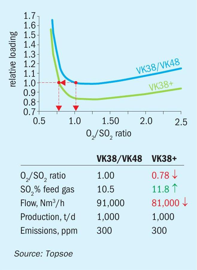
For example, a 3+1 double absorption sulphur-burning plant that originally processes 1,000 t/d with 91,000 Nm³/h of 10.5% SO2 gas requires a certain volume of VK38/VK48 to meet an emission level of 300 ppm. If this plant switches from use of VK38/VK48 to the same volume of high activity VK38+ catalyst, then it will be able to operate with an SO2 strength of 11.8% and a lower gas flow of 81,000 Nm³/h, without experiencing a change in production or emission level.
This flow rate reduction from 91,000 Nm³/h to 81,000 Nm³/h will cause a reduction of 18% in the total converter pressure drop. This will translate to a reduction in the blower’s power consumption of around 215,000 kWh/year, which corresponds to e53,000/year, using current European electricity prices (e0.247/kWh). Additionally, these 215,000 kWh/year will correspond to a CO2 reduction of 150 t/year.
How can VK38+ help reduce the pressure drop?
For some units, the use of a higher SO2 strength might not be possible due to certain equipment design limitations. In such cases, pressure drop can still be reduced by using a smaller volume of a higher activity catalyst to meet the required target. This is illustrated by the following example.
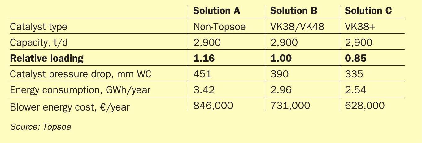
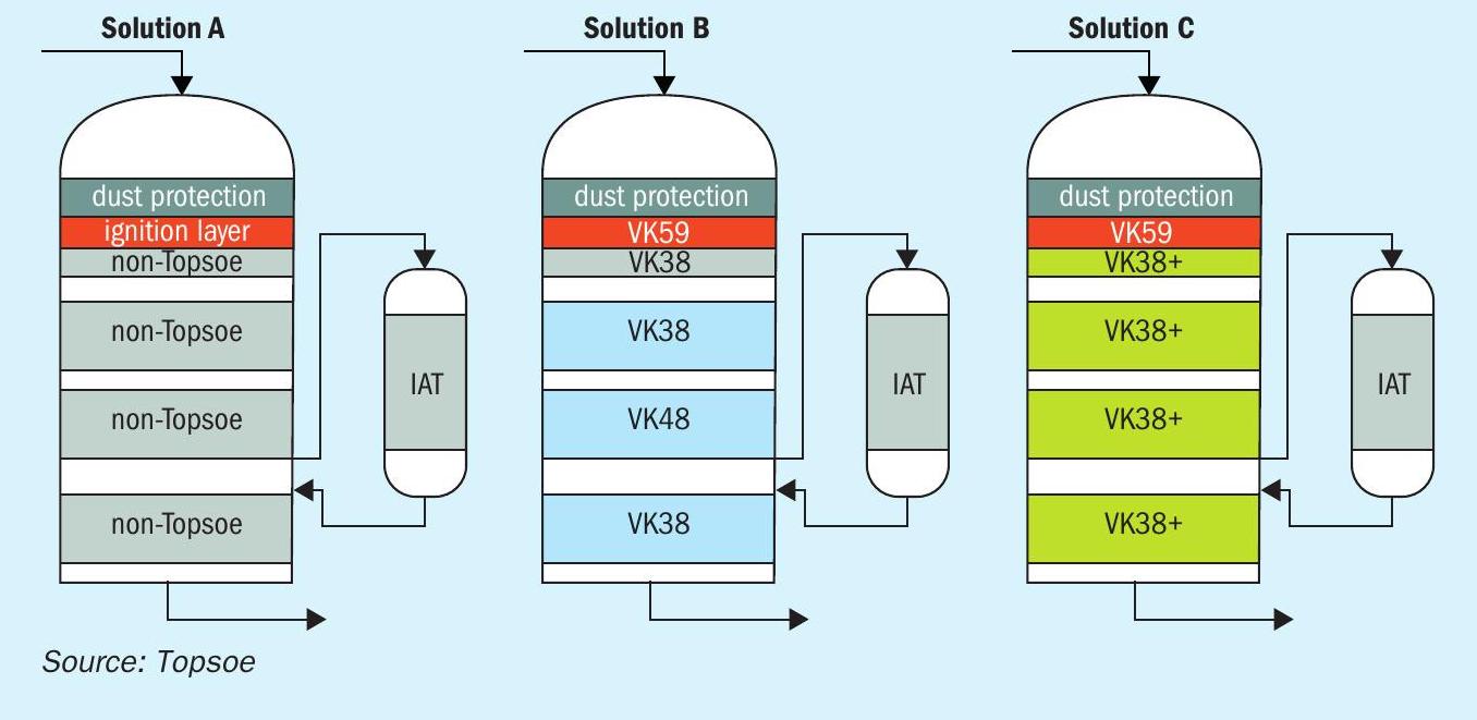
Fig. 5 compares three possible solutions proposed for a project of a new copper smelter unit, operating at 2,900 t/d, across two-year campaigns. Solution A utilises a non-Topsoe catalyst loading, Solution B utilises a VK38/VK48 catalyst design, and Solution C utilises a VK38+ catalyst solution. Each case assumes the same feed gas flow rate and composition, the same converter diameter, and the same SO2 emission level.
Estimated pressure drop and energy consumption for each scenario is shown in Table 2.
As shown in Table 2, the VK38+ solution could provide energy savings of up to 0.88 GWh per year. Across a two-year campaign, the same energy savings could be as high as e436,000 compared to Solution A and as high as e206,000 compared to Solution B.
These power consumption savings will also have a positive impact on carbon footprint: the VK38+ solution can reduce CO2 emissions by 1,200 t more per campaign, than the non-Topsoe solution, or around 600 t more than the VK38/VK48 solution.
Finally, it should be noted that reducing catalyst volume reduces screening work, which will most likely translate to shorter shutdown durations and more days spent producing acid. Reduced catalyst volume will also decrease associated catalyst disposal costs. These savings aren’t considered in the numbers shown in Table 2.
Conclusions
Switching from a standard design (VK38/ VK48) to a VK38+ setup provides the possibility of operating with stronger gases. This, in turn, gives operators the flexibility needed to reduce flow while maintaining production levels, which saves blower energy, or maintain flow in exchange for considerable acid and steam production increases. In cases where an increase in the strength is not possible, energy efficiency can be improved by reducing the catalyst volume and taking advantage of the higher activity of VK38+.
Whether the goal is to maximise acid and steam production or to reduce the blower’s power consumption, optimising the energy efficiency of the plant with VK38+, will not only rapidly compensate for the additional costs of a higher activity catalyst, but will also deliver important long-term financial and environmental benefits.