Fertilizer International 516 Sept-Oct 2023

30 September 2023
Nitrogen technology showcase
PRODUCTION TECHNOLOGY
Nitrogen technology showcase
Ballestra, Nitricity, Solex Thermal Science and Stamicarbon showcase their state-ofthe-art equipment and technologies.
STAMICARBON
Stamicarbon’s Ultra-Low Energy plant – first operational experience
Stamicarbon is the nitrogen technology licensor of Maire Group. The company’s latest process technology, the Launch Melt™ Ultra-Low Energy design, is proving a success with customers in East Asia and elsewhere.
The first two plants to apply this technology were the Jinjiang Xinlianxin and Hubei Sanning plants in China with a urea production capacity of 2,334 t/d each. They successfully went into operation in 2021. Two further installations, the Gemlik plant in Turkey and the Henan Xinlianxin plant in China, are under construction currently, while two other plants in China are at the design phase.
Additionally, Stamicarbon recently signed a contract for a new Ultra-Low Energy urea plant in Jiangxi province, China. This will be the seventh plant based on this innovative design and, with a capacity of 3,850 t/d, is also the largest to date (Fertilizer International 514, p10).
Ultra-Low Energy design is the next generation of Stamicarbon’s pool condenser and pool reactor technology. It incorporates proven proprietary advances and benefits from a much lower steam consumption.
Heat integration breakthrough
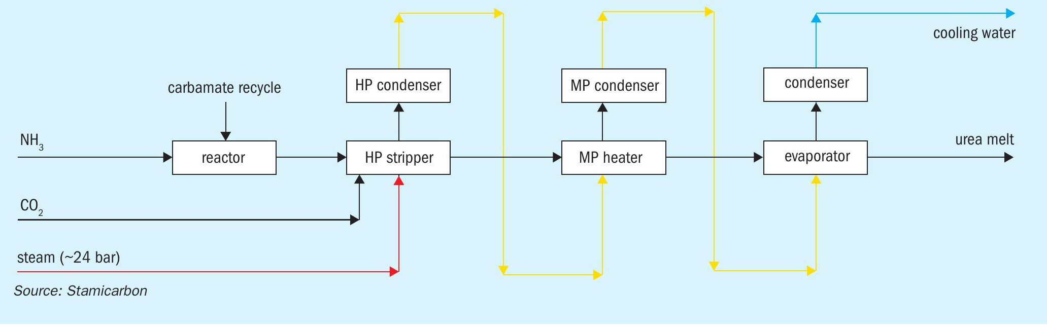
Traditional urea processes are based on the ‘N=2’ heat integration concept, so-called because the heat supplied to the urea plant, in the form of high-pressure steam (typically 23 bar and 330 °C), is used twice. Stamicarbon’s Ultra-Low Energy design is a breakthrough process that goes one step further by adopting N=3 heat integration –– enabling the heat supplied to be used three times instead of two (Figure 1). As a result, the urea plant’s overall steam consumption can be reduced by up to 40 percent and its cooling water consumption by about 16 percent, compared to traditional CO2 stripping processes.
In N=3 heat integration, steam is firstly used as a heating agent to obtain high stripping efficiencies in the high-pressure stripper. Subsequently, the heat is recovered by condensing the strip gas within the synthesis section in the high-pressure carbamate condenser, pool condenser or pool reactor. This is then used to generate low-pressure steam for use in downstream sections of the plant.
Process description
Ultra-Low Energy technology retains all the features of Stamicarbon’s previous pool condenser and pool reactor designs, such as reliability, operability, and the use of proprietary Safurex® stainless steels. At the same time, it substantially cuts operational expenditure (opex) by significantly reducing steam consumption.
The centrepiece of this technology, the Ultra-Low Energy pool reactor, does have major design differences. This reactor has two U-tube bundles, for example, handling two different fluid mediums. One bundle, the ‘steam bundle’, generates low-pressure steam, while the second ‘carbamate bundle’ is used for heat integration within the medium-pressure recirculation section.
Heat integration in the pool reactor is achieved as follows:
- The heat released by condensation of strip gas on the shell side of the carbamate bundle – at a pressure of about 144 bar and a temperature of 175°C – is used to decompose carbamate into ammonia and carbon dioxide on the tube side.
- The tube side of the carbamate bundle, in contrast, functions as a medium pressure heater.
- Essentially, this design configuration integrates the shell side and tube side functions of the U-tube bundle by taking full advantage of the available temperature difference between both process sides.
- It does this without a heat transfer medium.
- Importantly, the high heat transfer coefficient achieved allows the size of the carbamate bundle to be kept relatively small.
The amount of low-pressure steam generated by this pool reactor design is enough to satisfy urea process requirements.
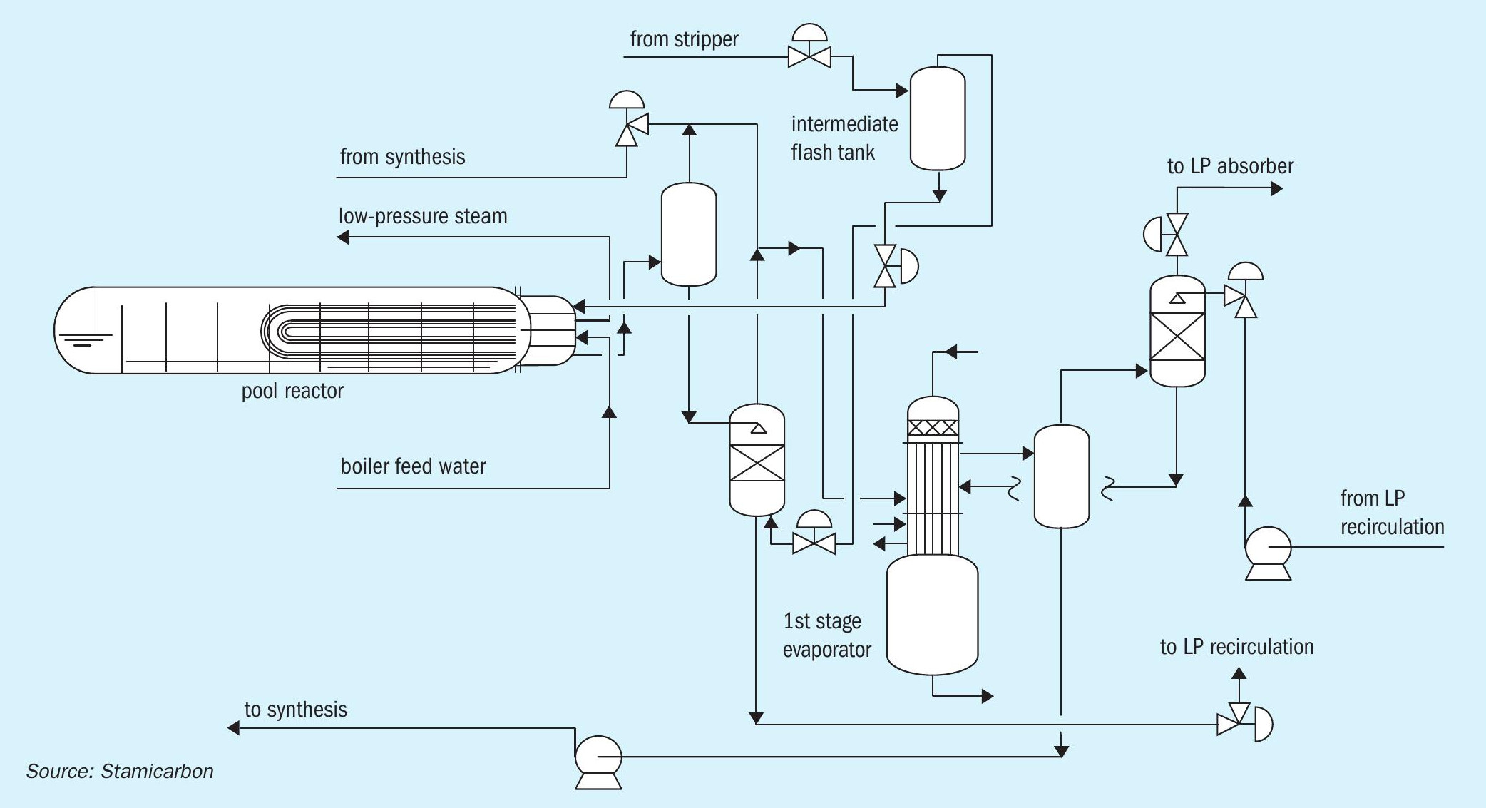
Stamicarbon’s Ultra-Low Energy design includes two high-pressure pieces of equipment: a high-pressure stripper and a high-pressure pool reactor (Figure 2). It optimises urea plant capital expenditure (capex) by avoiding the need for a high-pressure scrubber.
The absence of a high-pressure scrubber also lowers the height of the structure. Instead, the total height of the high-pressure equipment is limited to around 20 metres, this being determined by the elevation of the pool reactor, the urea plant’s heaviest piece of equipment. The high-pressure stripper, in contrast, is located close to ground level. Another vessel, the intermediate flash tank occupies the highest elevation at the plant.
First start-up experience
The Jinjiang Xinlianxin Ultra-Low Energy plant in China was the very first plant to operate with this innovative technology. This 2,334 t/d capacity plant successfully started up in February 2021 and produces prilled urea.
The plant’s staff were thoroughly trained by Stamicarbon on the company’s Operator Training Simulator prior to startup. This provided a good understanding of the expected behaviour of the overall plant and its reactor.
The plant’s start-up went very smoothly without any issues at the very first attempt. The plant was operated below full capacity initially until the feedstocks were assured. Production was then increased to above 100 percent of rated capacity during the first week of operation.
The energy consumption of the Ultra-Low Energy plant has set a new benchmark for urea production performance worldwide. Also, the presence of the medium-pressure recirculation section dampens disturbances that occur in traditional CO2 stripping plants due to the direct discharge of liquid from the stripper operation into the low-pressure section.
Actual plant performance parameters from the operation of the Jinjiang Xinlianxin plant are shown in Table 1. These results demonstrate the major advances in urea process technology achieved by the Ultra-Low Energy concept at an average plant operating capacity of 102 percent.
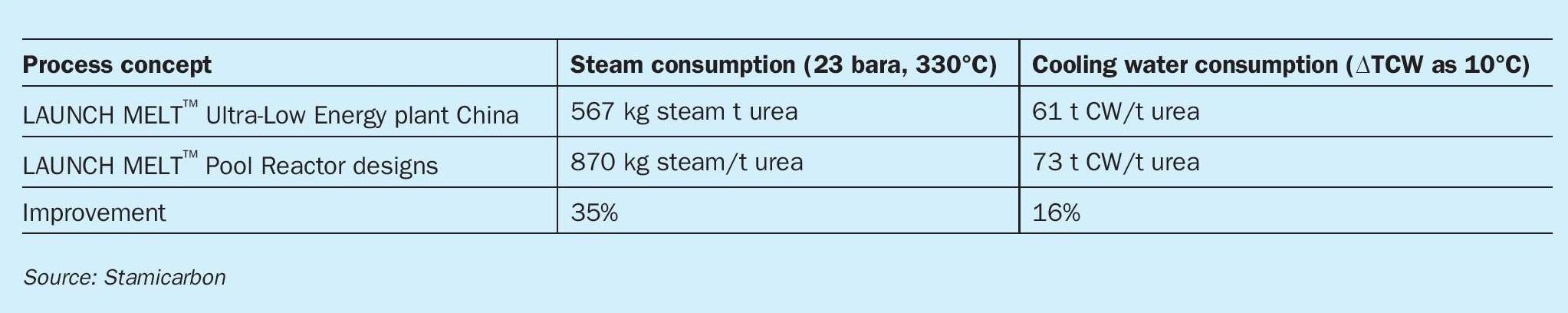
The plan’s actual high-pressure (23 bar, 330°C) steam consumption (567 kg/t urea) is even lower than the value predicted during the design stage. Optimisation of process conditions – i.e., the ammonia feed temperature to the synthesis section – is expected to reduce steam consumption by a further 20-25 kg/t urea.
Overall, the plant’s innovative design reduces steam consumption by about 35 percent and reduces cooling water consumption by about 16 percent, compared to the traditional pool condenser and pool reactor designs. This is achieved without extra investment cost as the capex of an Ultra-Low Energy plant is comparable to previous traditional designs.
The successful commissioning and stable operation of the Jinjiang Xinlianxin plant also validated the mechanical design and construction materials used in the Ultra-Low Energy pool reactor. The design fully employs Safurex® Infinity∞ steel and therefore benefits from the superior resistance to corrosion this provides.
Plant maintenance is also straightforward. The opening of internal covers, which are fully accessible through the manway, enables unrestricted and non-destructive testing inspections of the tube bundles and the internals of the distribution box without the dismantling of heavy parts.
Ease of operation is another important benefit of Ultra-Low Energy plants compared to those based on traditional urea technology. This key advantage convinced the same Chinese customer to commission a second Ultra-Low Energy plant from Stamicarbon, which is currently under construction, and a third Ultra-Low Energy plant, which is currently under design.
Ultra-Low Energy technology is also-suitable for revamping, irrespective of the original technology or capacity. Valuably, its use in plant revamps can increase urea production capacity, by replacing the existing outdated reactor, while simultaneously reducing plant energy consumption. n
BALLESTRA
Moving methylene-urea production to the fertilizer industry
What if the means of delivering a step change in nutrient use efficiency was a product, methylene-urea, already available to the fertilizer industry?
Currently, the production of this compound is limited by the small size of the resin industry that supplies it. Ballestra is therefore working to scale-up methylene-urea manufacturing technology to allow the large-scale production of this slow-release fertilizer within the fertilizer industry.
Methylene-urea chain compounds
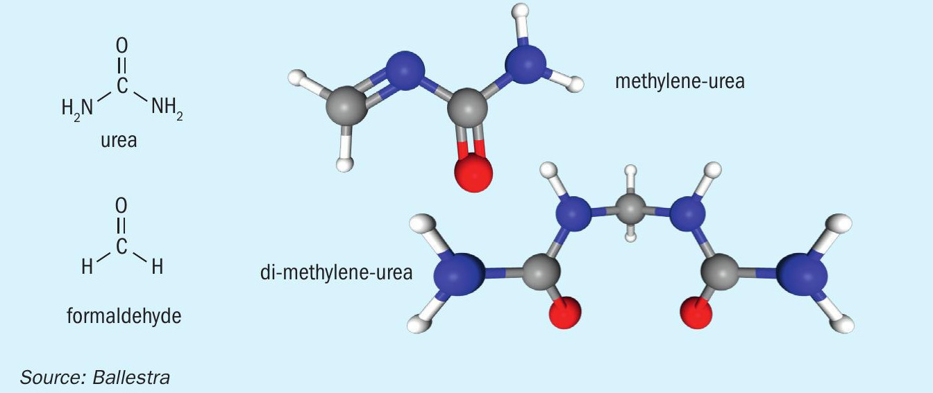
Methylene-urea (Me-urea) is obtained by condensing together one molecule of urea with one formaldehyde molecule. If condensation continues, more molecules join together to form di-methylene-urea (Figure 1). Proceeding further with polymerisation increases the chain length and a compound known as ureaform is then formed. The ultimate end product of this polymerisation process is a urea-formaldehyde (UF) resin made up of long reticulated molecular chains.
These types of compounds are already well-known within the nitrogen industry. Urea-formaldehyde concentrate (UFC), for example, is an essential additive used to impart mechanical resistance and hardness to urea granules. There is also good awareness of formaldehyde as it occurs as a product of the partial oxidation of methanol, a major basic chemical and close relatives of ammonia.
Valuable slow-release properties
Urea is very soluble in water while UF resins are completely insoluble. The various methylene-urea chain compounds – Me-urea, di-methylene urea and ureaform – sit somewhere in between these two extremes and are partly soluble. Generally, these compounds become more insoluble as their polymer chain length increases.
Urea, Me-urea, di-methylene urea, urea-form and UF resins are all excellent nitrogen carriers and can therefore be used as fertilizers. The slow-release properties of methylene-urea chains can be precisely engineered to dissolve and make nitrogen available within days, weeks, or months, according to the requirements of a particular crop. These compounds will resist water leaching depending on their polymer chain length, starting from urea (very soluble) and arriving at UF resins (insoluble).
Me-urea and longer chain ureaform fertilizers are available in both liquid and granular form and are considered safe for both humans and the environment. These slow-release nitrogen fertilizers, when applied as a foliar liquid, have been shown to be 4-5 times more efficient than conventional nitrogen fertilization, i.e. 4-5 kg of urea are needed to deliver the same yield effects as 1 kg of Me-urea. Granular Me-urea offers similar efficiency advantages and is widely applied in turf (e.g., golf courses) and ornamental markets as well as in agriculture. Both liquid and granular products do not result in crop burn as they have a low salinity and no nitrate content.
Low volumes, high prices
The valuable fertilization properties of Me-urea compounds are said to have been discovered when grass surrounding a urea-form tank grew greener and taller because of a leak. In reality, Me-urea is a well-studied and well-known product that has been sold and used for decades. It is a proven slow-release fertilizer that is attractive in the wider world market and can therefore command premium prices.
Currently, Me-urea is manufactured by the UF resin industry, a much smaller industrial sector compared to the fertilizer industry, with installed capacity limited to a few hundred thousand tonnes per year.
Interestingly, though, this compound is made from chemicals already found in fertilizer production processes. That opens up the possibility that the fertilizer industry itself could begin to produce Me-urea, rather than sourcing this externally. This would allow fertilizer producers themselves to deliver the necessary step change in nutrient use efficiency – without sharing added value and margins with third parties. Indeed, in this article, we explain how Me-urea manufacturing can be moved from the UF resin sector to the fertilizer industry where it belongs.
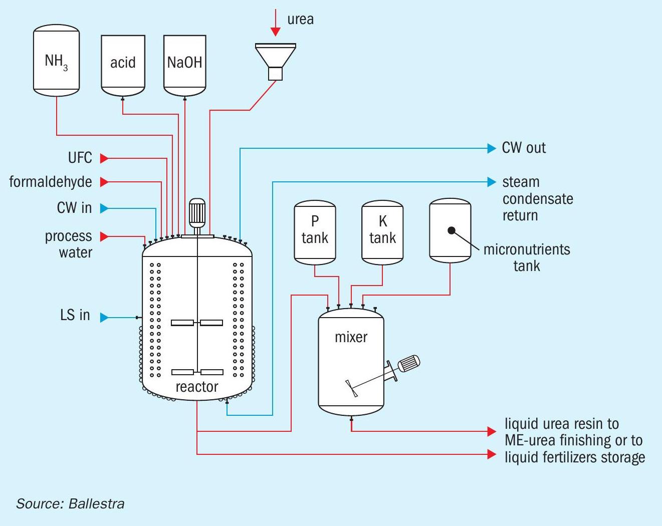
Methylene-urea production
Ballestra’s Me-urea production system (Figure 2) closely follows the approach already taken by the UF resin industry. The process design guarantees a fully automated, safe and durable production system, with no volatile organic compound emissions. Operators, by adding the recipe to the control system, are ready to go.
The core know-how behind Me-urea production is the process recipe. The use of a batch reactor allows this to be changed easily to deliver different product grades. UFC or formaldehyde are loaded with solid urea or urea solution into the reactor. Polymerisation via acid or basic catalysis is performed in closely controlled cycles with the conditions varied to obtain a specific polymer length (or mix of polymer lengths).
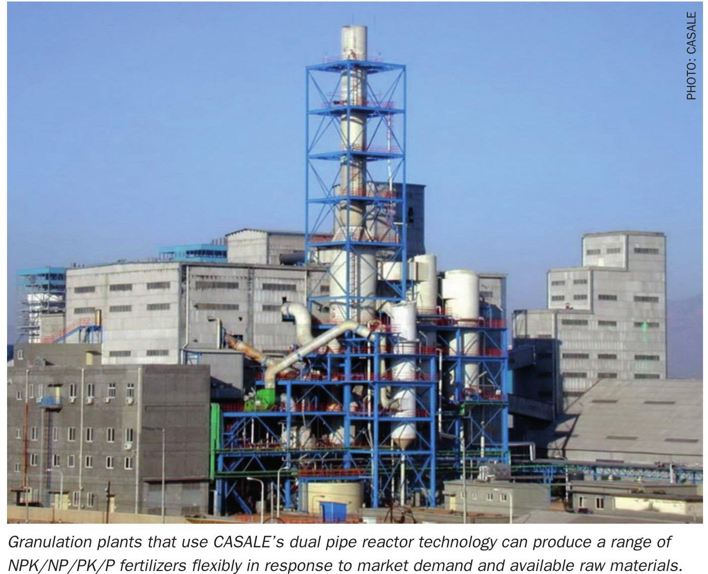
The product obtained can be stored as a liquid nitrogen fertilizer or mixed with other nutrients and micronutrients to obtain a precisely formulated liquid NPK fertilizer. Both of these product types can also be sent for further finishing in a drum granulator.
Although Me-urea production technology is well established, the finishing stage is where most existing plants fall short. This is also the reason why the production capacity of a single Me-urea line is generally limited.
Me-urea is actually a family of different products, not a single product based on a well-defined commercial specification. Because of this, each individual process recipe will require a specific set of finishing parameters for the Me-urea product obtained. However, most available granulation technologies do not have the flexibility to cope with the full range of Me-urea product grades.
This is where Ballestra’s fluid drum granulator excels. Essentially, this is comprised of a rotating drum with a fixed table inside made of a perforated metal sheet (Figure 3). The rotation of the drum lifts the granules onto the table, where they are kept in fluid bed conditions by air flowing through holes in the metal sheet. The perforated table is slightly inclined to one side.
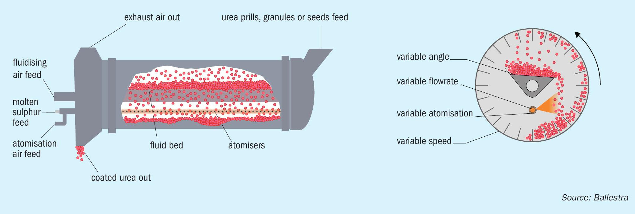
This allows dry granules from the fluid bed to fall back to the lower part of the rotating drum. While doing so, they pass through an incoming spray of fresh Me-urea, which creates a further layer of material.
Everything in the design is about flexibility. The following parameters can all be carefully regulated:
- The drum’s rotation speed
- The inclination of the fluid bed table
- The temperature and flow of the fluidising air
- The temperature of the freshly sprayed liquid.
Once the proper parameters for each recipe are defined, the result is granules with a solid, onion-like, layered structure and a hardness and mechanical resistance far greater than those of standard urea granules. A notable feature of Ballestra’s fluid drum granulator is that the fresh solution is sprayed into an area away from the fluidising air flow. This limits droplet entrainment, compared to a standard urea granulation process, and therefore reduces the duty on the downstream air cleaning section.
Setting aside these differences, the overall finishing scheme for Me-urea (Figure 4) resembles a simplified urea fluid bed granulation process.
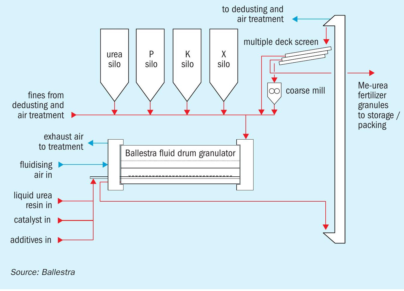
More products from the same plant
The finishing process described here is not limited to just Me-urea and ureaform production. Its flexibility also enables the production of other, more complex types of slow-release fertilizers.
Prior to finishing, Me-urea and urea-form, because they are basically UF resins with shorter polymer chains, behave like a glue. Other nutrients can therefore be added as feed particles to the Ballestra fluid drum granulator and become evenly embedded within the solid and hard matrix of Me-urea granules. The resulting NPK and multi-nutrient granules have the same slow-release properties as standard Me-urea granules. This holds true even when the granule is broken as the added nutrients are still firmly fixed within the Me-urea matrix.
The fluid drum granulator can also be used as a quick and economical way of modifying the physical behaviour of urea granules and prills – by, for example, improving their slow-release properties, surface resistance and bulk flowability. This is achieved by coated or fattening urea prills and granules fed to the Ballestra fluid drum granulator with a layer of Me-urea.
The resulting granules have a core of pure urea surrounded by an Me-urea coating. The release of the urea core to the soil can be carefully timed by regulating the thickness of the outer Me-urea coating.
Applying Me-Urea coated urea granules to soils alongside seeds, for example, could provide a fertilization boost exactly when growing crops need it. Furthermore, supplying mixed granules with coatings of different thicknesses can provide a series of fertilization boosts at specific times. The end result is precision engineered fertilizer granules designed to deliver nutrients at specific times to closely match crop requirements.
Partners on a common journey
Ballestra invites partners to help us shift methylene-urea production away from the UF resin and laminates industry and embed production within the fertilizer industry instead where it belongs. We believe this will make a significant contribution to fertilizer industry sustainability and improve nutrient use efficiency.
As a company, Ballestra offers robust and scalable process and finishing technologies, as well as agronomic, marketing and regulatory support, plus the expertise to deliver new fertilizer product recipes. By combining these strengths with industry partners who have the necessary feedstock availability, marketing push and innovative spirit, methylene-urea technology could be scaled up to meet actual market demand.
New products, intellectual property (IP) and applications could also be jointly developed. Achieving reductions in natural gas consumption during fertilizer production would be another worthwhile objective.
NITRICITY
Bridging renewable electricity and food production
Challenges and opportunities
Nitrogen fertilizers are the foundation of modern agriculture and play a central role in global food security. Indeed, it is estimated that around 50 percent of the global population depends on the food produced by these synthetic crop nutrient products.
Today, nitrogen fertilizers are manufactured on a large scale at highly centralised production sites using coal or natural gas as the main feedstock, in combination with water and air. These plants use the traditional Haber-Bosch process to fix molecular nitrogen (N2 ) from the atmosphere into ammonia (NH3 ).
The ammonia generated in this way can be used directly as fertilizer, when injected into the soil (as is typical in the US Midwest), or instead used as a raw material to produce other nitrogen fertilizers, such as urea and urea ammonium nitrate (UAN).
The Haber-Bosch process revolutionised how nitrogen fertilizers are made and has undoubtedly helped to feed an expanding global population. Haber-Bosch’s use of fossil fuels as the main feedstock in nitrogen fertilizer production has, however, becoming a growing concern. For every kilogram of fixed nitrogen obtained, the process generates around 2-4 kilograms of carbon dioxide (CO2 ) emissions – the exact amount depending on the type of hydrocarbon feedstock consumed and the individual production process.
Additionally, when nitrogen fertilizers are applied to cropland, they decompose to provide plant-available forms of nitrogen [nitrate (NO3 -) and ammonium (NH4 +)] and nitrous oxide (N2 O), a greenhouse gas (GHG) 300 times more potent than CO2 . Overall, the global production, distribution, and application of nitrogen fertilizers results in 2.88 gigatons of CO2 -equivalent emissions annually, an amount that represents more than six percent of world GHG emissions.
NH3 produced by the traditional Haber-Bosch process is referred to as ‘grey’ ammonia. Currently, there are two main ammonia production routes available to reduce CO2 emissions. The first, the ‘blue’ ammonia route, still uses natural gas as a feedstock and cuts CO2 emission via carbon capture and storage (CCS) or other mechanisms. The other route produces ‘green’ ammonia from hydrogen (H2 ) generated by water electrolysis using renewable electricity, instead of sourcing this from natural gas. While both are valid solutions, they each have significant drawbacks. Green ammonia production requires high capital expenditure, for example, and blue ammonia still consumes natural gas and only partially eliminates CO2 emissions.
The new geopolitical landscape that has emerged since the start of the Russia-Ukraine conflict presents the industry with another challenge. The conflict has triggered an energy crisis in Europe and a global nitrogen fertilizer price rally due to the limited supply of Russian natural gas.
As a result of the conflict, natural gas prices in Europe increased from around $25/MMBtu in January 2022 to a peak of $70/MMBtu in March 2022. Although natural gas prices have receded since then, the global outlook for the interconnected fertilizer, food and energy markets over the next couple of years remains volatile and uncertain due to increased tensions between Russia and Western nations.
In Europe, the impact of the conflict has been unprecedented, with ammonia production curtailments and plant shutdowns across the continent resulting in periods of high nitrogen fertilizer prices across the globe. A major concern is how this will impact food security in the coming years, with many growers across the world reducing their fertilizer application rates in response to high prices.
In a market encountering increasing complexities, from fertilizer production to logistics bottlenecks to climate change, concerted efforts by different players will be necessary to ensure nitrogen fertilizer production remains sustainable and resilient moving forward. In particular, while current systems and technologies have worked well, innovation is now necessary if the fertilizer industry is to adapt to changing circumstances. Global food security depends on it.
Nitricity – part of the solution
Nitricity offers a wholly different approach to fertilizer production. The company’s technology produces water-soluble fertilizers such as calcium nitrate from relatively small production hubs using only air, water, and renewable electricity. Taking the long-term view, this will bring nitrogen fertilizer production closer to the end user while boosting domestic production and reducing reliance on natural gas.
The company was founded in 2018 with the mission to electrify and distribute the production of nitrogen fertilizer. By avoiding the use of fossil fuels (natural gas and coal), Nitricity’s technology has the potential to produce cost-effective, climate-smart nitrogen fertilizer for farmers and other stakeholders, while minimising the environmental impacts of fertilizer production, distribution, and application. The company’s co-founders are former Stanford PhD and postdoc students with extensive backgrounds in catalysis, chemical engineering, and nitrogen-fixation technologies.
Lightning in a bottle
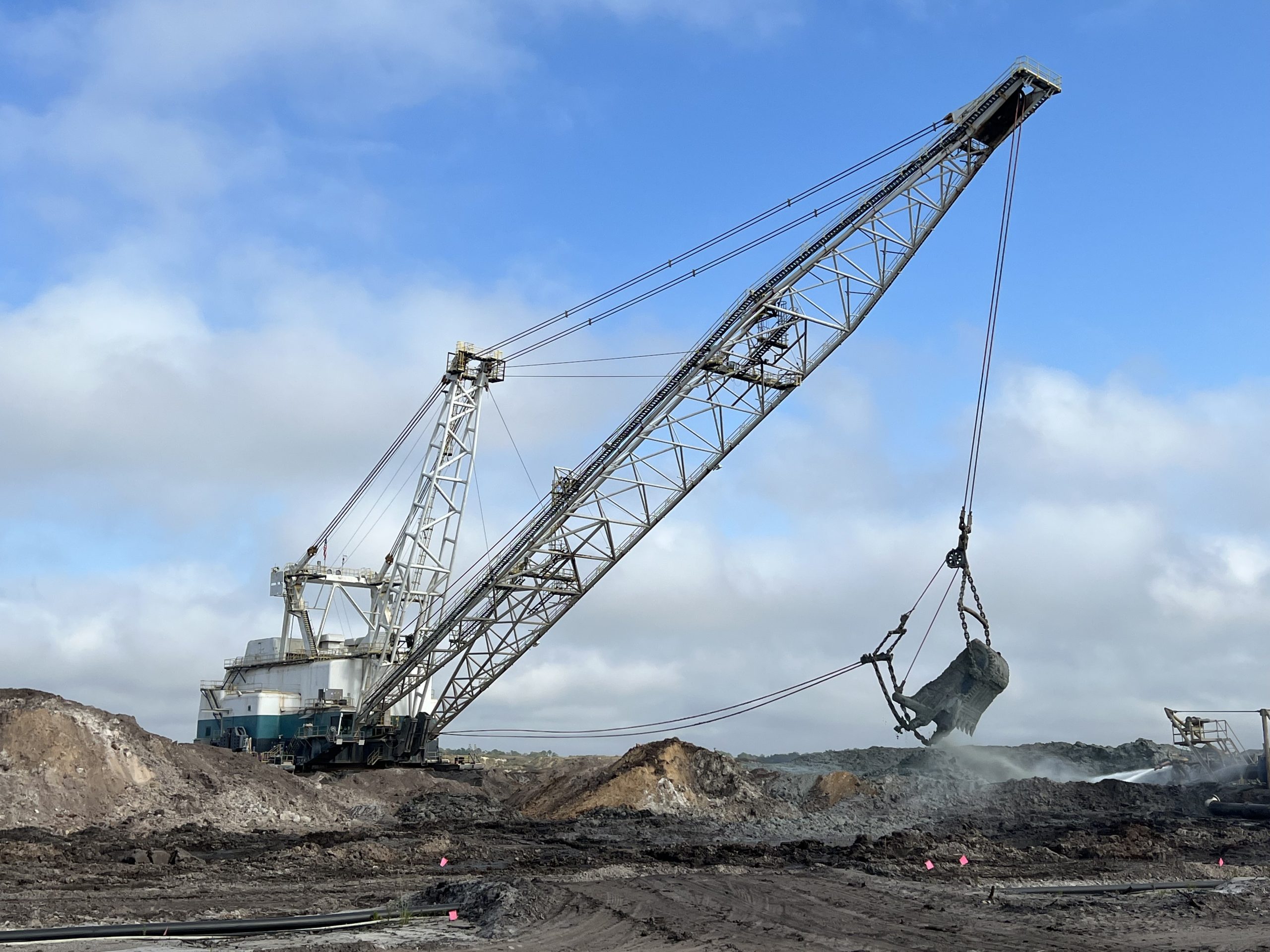
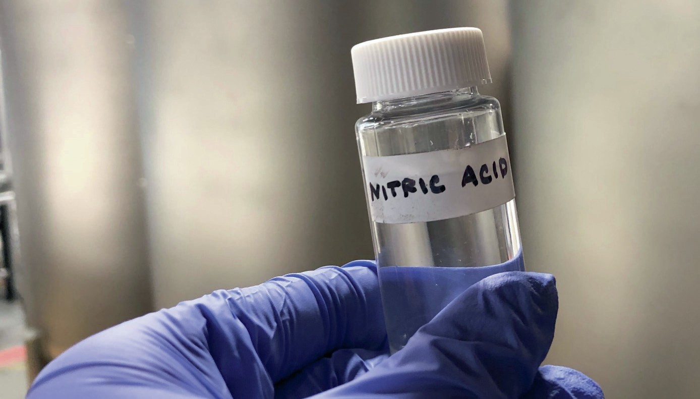
Nitricity’s process mimics the nitrogen fixation that occurs in nature during lightning strikes. It emulates this natural process by using renewable electricity to generate plasma – essentially ‘lightning in a bottle’ – to break down molecular nitrogen (N2 ) in the air. Once N2 is cracked, it reacts with oxygen in the air to form NO and NO2 inside a plasma reactor. A series of absorption columns efficiently capture and dissolve these species in water to produce nitric acid (HNO3 ).
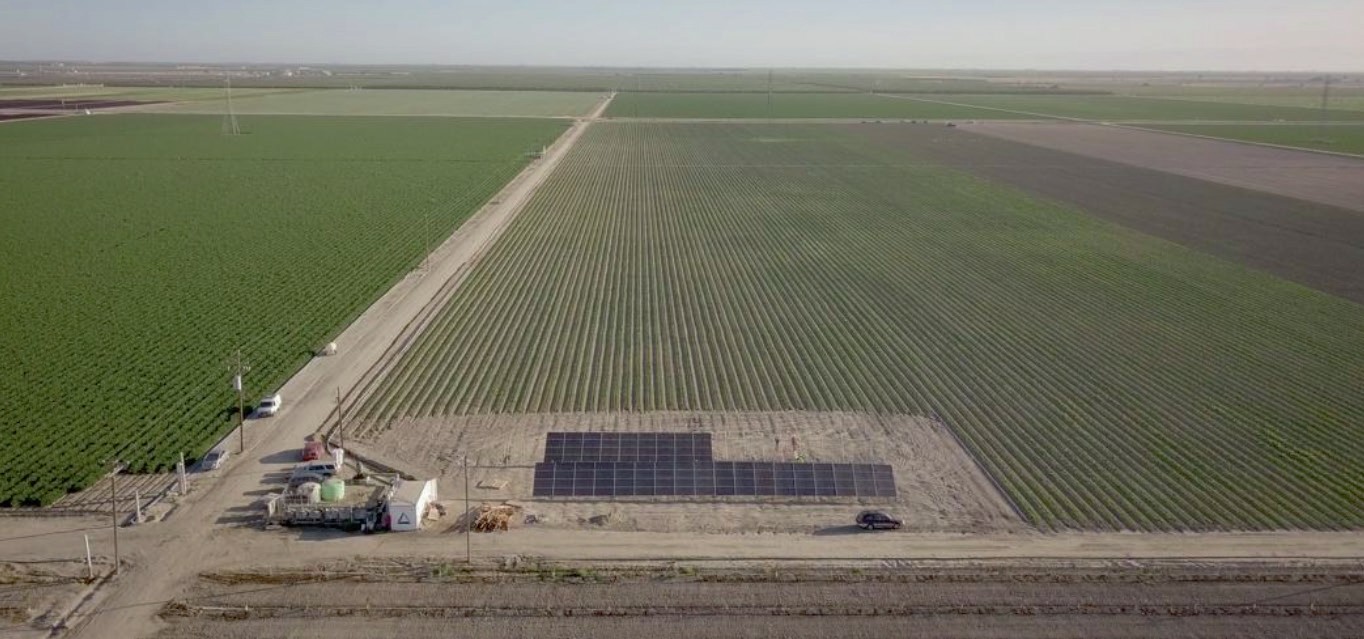
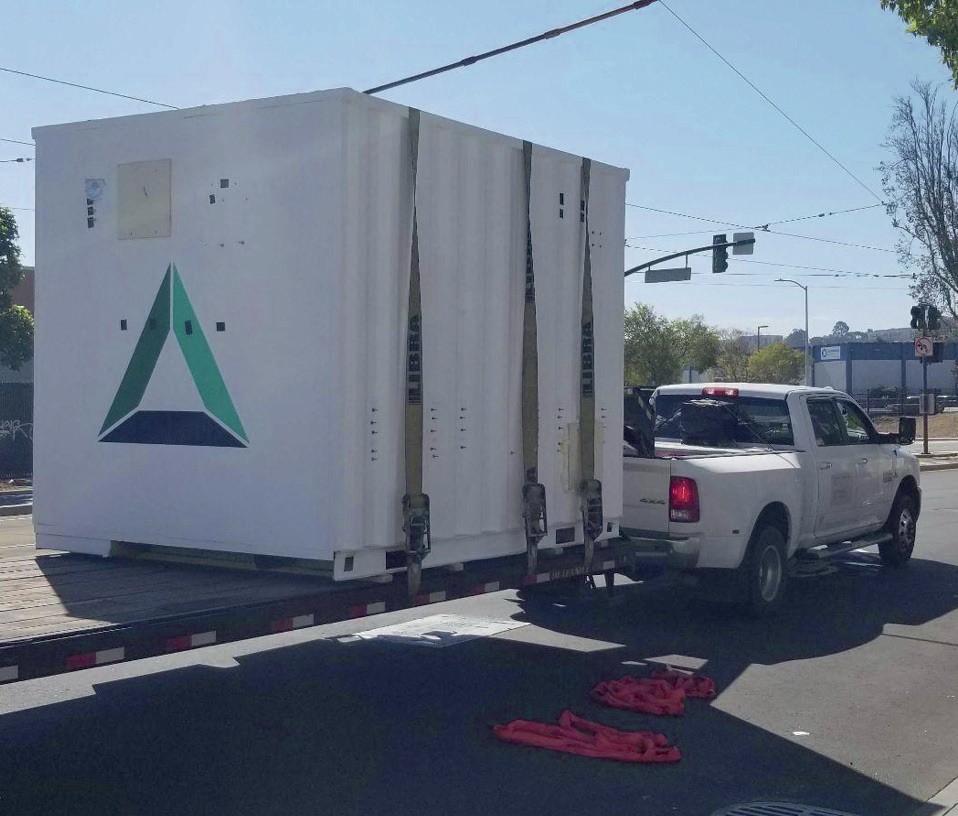
The ‘green’ nitric acid obtained can be used to make high-value nitrate-based fertilizers by reacting it with materials such as calcium carbonate, potash, and phosphate rock. Nitricity’s production setup, which includes solar PV equipment, advanced plasma reactors and absorption columns, was successfully demonstrated at a solar-fertilizer project in Fresno County, California (see main photo).
In its scale-up journey, Nitricity is currently working to develop bigger and more efficient plasma reactors at its new headquarters in Fremont, California. This new system will be used to deliver Nitricity’s fertilizer production hubs. These are expected to arrive on the market and be commercially available within two years.
The major benefits of Nitricity’s technology that underpin its go-to-market strategy are:
- Non-fossil fuel process. Nitricity’s technology will make ‘green’ fertilizers with low GHG emissions. It also makes the value chain more resilient since it does not rely on the volatile natural gas market.
- Distributed fertilizer production. Nitricity’s vision for the future is to build distributed production systems able to serve a wide range of acres.
- Local production. Nitricity’s technology allows the local production of nitrogen fertilizer – something that has not been possible until now in a market dominated by large production plants that depend on natural gas.
- Increased competition. The fertilizer industry is heavily concentrated with a few large players controlling the majority of nitrogen fertilizer production.
- More efficient fertilizer. Nitricity will make nitrate-based fertilizers which, from an agronomic perspective, tend to be more efficient than ammonium-based fertilizer (e.g., urea) and also generate less nitrous oxide (N2 O) when applied in the field.
The importance of partnerships
Nitricity has been fortunate to have several partners that share its vision to electrify and distribute nitrogen fertilizer production.
Nitricity closed its Series A fundraising round in August 2022. This raised $20 million and was led by Khosla Ventures and Fine Structure Ventures with the participation of Energy Impact Partners, Lowercarbon Capital, and MCJ Collective.
Nitricity was also selected by Elemental Excelerator to be part of their 11th cohort of investments – this comprising 17 companies focused on climate technology and decarbonisation. The investment from and guidance of Elemental Excelerator will bolster Nitricity’s plans for growth, particularly the ambition to operate its renewable fertilizer technology at scale in agricultural applications.
In research initiatives, Nitricity is partnering with the prestigious and globally renowned International Fertilizer Development Center (IFDC) in Muscle Shoals, Alabama (see photo). This collaboration is revealing Nitricity’s current GHG emissions profile and identifying opportunities for further reductions. More recently, Nitricity has partnered with Frontier and IFDC to accelerate the integration of carbon removal alongside fertilizer production from air, water, and renewable energy.
SOLEX THERMAL SCIENCE
New face to waste heat recovery
A recent acquisition by Solex Thermal Science is expected to help the thermal energy and bulk materials specialist company grow its waste heat recovery business within the fertilizer industry.
Canadian-headquartered Solex announced the purchase of Econotherm, a leader in waste heat recovery technology, in June this year. Econotherm manufactures heat pipe heat exchangers that capture difficult-to-recover heat from industrial sources including hot and/or dirty exhausts. The UK-based company was established in 2007 and currently operates in the automotive, metals, construction, food, mining, oil and gas, power generation and pharmaceutical industries.
Better together
The Econotherm acquisition was a natural progression for Solex, according to CEO Lowy Gunnewiek, as both companies share a passion for working with customers to best address their operational needs.
“Our global client base in industries such as fertilizer has been asking for an even deeper suite of best-in-class, sustainable solutions that align with their operating needs and respective environmental, social and governance strategies,” says Gunnewiek. “By combining Econotherm’s deep expertise in waste heat recovery with our established heat exchanger solutions, we now have much deeper capabilities to help customers produce a better product at less expense to them and the environment.”
Solex is a global market leader and developer of high-efficiency, indirect heat exchange technology for the heating, cooling and drying of free-flowing granular materials such as solid granules, pellets, beans, seeds and particles.
Over the past 30 years, the company has installed some moving bed heat exchangers (MBHEs) in more than 50 countries worldwide. Originally serving the Canadian fertilizer industry, Solex has since expanded into other industries such as oilseeds, sugar and industrial materials such as minerals/sands, chemicals and polymers.
Delivering the energy transition
Solex’s acquisition of Econotherm comes at a time when the company’s heat exchangers are being widely installed within the energy transition sector – with a particular focus on industrial waste heat recovery.
Igor Makarenko, Solex’s Global Director, Fertilizer, believes there is great potential to build on the existing success of the company’s plate-based technology by ‘upcycling’ more energy from hot working fluids during cooling processes.
“In most cases, the hot fluid that comes out of our moving bed heat exchangers, when cooling fertilizer, is sent to a cooling tower where all the energy within it is rejected to the ambient air,” observes Makarenko. “However, this energy can be used in other locations of the plant as useful thermal energy.”
The recovered heat can be used, for example, to pre-heat air for combustion systems upstream in the production process – generating the heat needed by equipment such as fluid beds or rotary drum dryers. Alternatively, the recovered heat can be used to pre-heat air to ‘trim dry’ the fertilizer in MBHEs.
“We are also looking at combining our MBHEs with industrial heat pumps to upcycle the energy from waste to a heat source,” says Makarenko. “Heat pumps, being electrically driven, do not create any additional CO2 emissions either.”
Complementary technologies
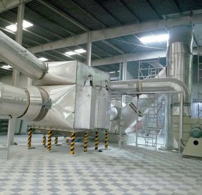
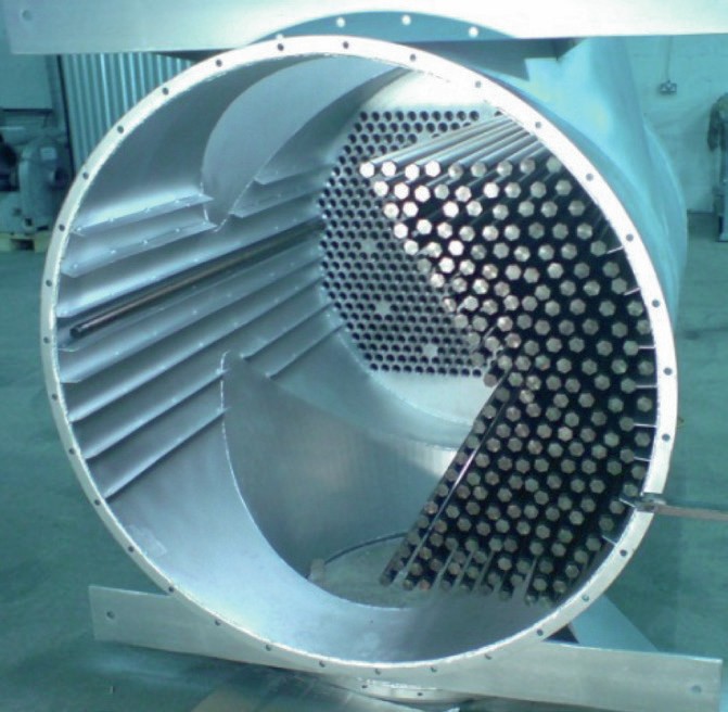
Econotherm’s heat pipe heat exchangers (see photo) will complement Solex’s existing technology during drying and other process stages, according to Mark Boocock, the company’s Managing Director, as well as providing new opportunities for heat recovery and re-use in other areas of the fertilizer production process.
Econotherm’s patented superconductor heat pipe heat exchangers can extract heat from ‘one-pass air’ and then use this to pre-heat ambient air that goes back into the dryer. In Boocock’s view, Econotherm’s technology has clear and obvious potential for recovering energy from the particle-laden air generated as exhaust during fertilizer drying processes.
“With heat pipe heat exchangers, fertilizer producers can reduce the natural gas consumption needed for drying fertilizer, while also reducing the temperature of the air that’s being sent to the scrubbers” says Boocock. “To reduce scrubbing cacpacity, our heat exchangers will also remove some of the particulate load in the air stream.”
Upstream fertilizer applications
Ammonia and nitrate production – manufacturing steps further upstream in nitrogen fertilizer plants – are other process areas where heat pipe heat exchangers can be productively used to capture otherwise wasted heat, predicts Boocock.
Ammonia production, for example, employs large gas-fired heaters that supply heat to steam reformers. Solex and Econotherm will therefore be jointly exploring opportunities to recover heat from the exhaust gas coming out of these gas-fired heaters. This has the potential to reduce the amount of primary energy needed in steam production by reintroducing recovered heat back into the heater.
The installation of Econotherm’s technology in fired heaters in the oil and gas industry is, says Boocock, already saving its customers “millions of dollars each month” in reduced fuel costs and is cutting greenhouse gas emissions. The use of heat pipe heat exchangers in this sector is long established and has been highly successful.
“It’s making a profound difference,” says Boocock. “Our solutions, many of which are first-of-its-kind installations, have achieved successful energy savings in applications otherwise considered unsuitable for conventional heat exchanger equipment.”
The turbines and condensers in nitric acid production, meanwhile, act as large heat sinks, notes Boocock. In his view, the significant exhaust streams coming out of these front-end turbines provide ideal opportunities for waste heat recovery.
Eliminating catastrophic failures
Additionally, the shell-and-tube heat exchangers normally used to remove heat from tail gas/nitrous gas downstream of boilers can be difficult to manage, suggests Boocock. Typical problems include thermal stress cracking caused by differential expansion between surfaces and casings, and the condensation induced by cold spots leading to corrosion. The traditional thin metal surfaces of shell-and-tube heat exchangers are also vulnerable to erosion and corrosion.
Econotherm’s technology, in comparison, is much less prone to these operational issues. In heat pipe heat exchangers, pipes can expand and contract freely without applying stress to casings, for example, while their isothermal operation eliminates cold spots and condensation. Because heat transfer is not affected by wall thickness, thicker walls are also used with this technology – typically 2.5-3.5 millimetres – providing higher erosion allowances.
Heat pipe heat exchangers also eliminate the catastrophic failures associated with other types of heat exchanger. This is because of built-in multiple redundancy, an intrinsic feature of the technology. Each heat pipe within Econotherm’s equipment functions independently and autonomously.
“As a result, in general, the consequence of failure is minimised and manageable,” says Boocock, whose company is at the forefront of heat pipe research and development.
“There is a lot of waste heat coming out of a fertilizer plant that’s not being recovered. What we are offering is a type of heat exchanger that moves the risk and return on investment indicators in a positive direction – allowing fertilizer producers to look closer at their existing processes,” sums up Boocock.