Nitrogen+Syngas 386 Nov-Dec 2023
30 November 2023
Reducing the carbon footprint of ammonia plants
AMMONIA SYNTHESIS CATALYST
Reducing the carbon footprint of ammonia plants
With the current focus on decarbonising ammonia production, Tom Davison of Johnson Matthey explains the important role of high activity ammonia synthesis catalyst in the production of green ammonia.
In the transition to a low carbon economy there is an ever increasing need to develop technology to decarbonise the chemicals, fuel and energy sectors. Along with decarbonising ammonia production for the existing markets of fertilizer and speciality chemical production, ammonia is also seen as a key part of the future energy strategy as an effective hydrogen transport vector. In countries with emissions trading schemes there is an extra incentive to reduce a plant’s carbon footprint, especially in Europe where carbon prices have risen considerably in early 2022. The volatile and high gas prices being seen in a lot of regions over the last couple of years are also an effective driver to increase plant efficiency in order to drive down opex costs. For new plant designs the focus on green and blue ammonia flowsheets as an effective way of addressing these issues and these technologies are key to achieving GHG reduction targets, whereas for existing conventional plants the transition is more difficult and will be more gradual, with revamps or replacement over time to low carbon alternatives.
Away from the established markets for ammonia in fertilizers and chemical production, which will continue to grow, there is also projected to be a large emerging market for ammonia as a hydrogen transport vector. A lot of developmental focus was initially going into green hydrogen production as a source of fuel or energy vector/storage medium, but hydrogen itself is not the best choice, having a low energy density and being difficult to store and transport. Looking at other potential choices, ammonia is currently considered a front-runner as a hydrogen transport vector due to a high hydrogen density (120 kg H2 per m3 at -33°C, 1 atm)1 and existing infrastructure for storage and transportation associated with the mature fertilizer and chemicals industry. Ammonia can also be used as a fuel itself, either as pure ammonia or partially decomposed ammonia along with the option to fully decompose to hydrogen for use in fuel cells or energy generation. Whilst ammonia does not contain carbon, so there isn’t the potential issue of CO2 generation at point of use or decomposition, care does need to be taken in the design of ammonia crackers or when using ammonia as a fuel to minimise/abate NOx emissions and N2 O, which is in itself a potent greenhouse gas. Plants to service this market will be blue or green ammonia designs and are projected to make up the majority of the new ammonia plants being built in the mid to long term.
Clean ammonia production
Blue ammonia
Blue ammonia will be a key technology in the drive to low carbon ammonia and energy, whilst carbon dioxide is still produced by the process, it is produced in a form which can be captured and sequestered. This technology is closer to a conventional “grey” ammonia plant and as such in the short term is more viable for the bulk of the large-scale new ammonia plants, whereas green ammonia technology at this scale will likely become more prominent in the mid to long term. The major differences between existing “grey” ammonia plants and blue ammonia flowsheets are around the reforming section, with auto-thermal reforming (ATR) technologies such as Low Carbon Hydrogen LCH™ being used to generate hydrogen as this means that up to 99% of CO2 can be captured within the process. The conditions within the synthesis loop will be within the bounds of currently operating plants. Both KATALCO™ 35 series and the high activity KATALCO 74 series catalysts have proven strong performance at these conditions – in particular the KATALCO 74 series catalysts can be used to maximise activity within the ammonia synthesis reactor and optimise loop performance.
Green ammonia
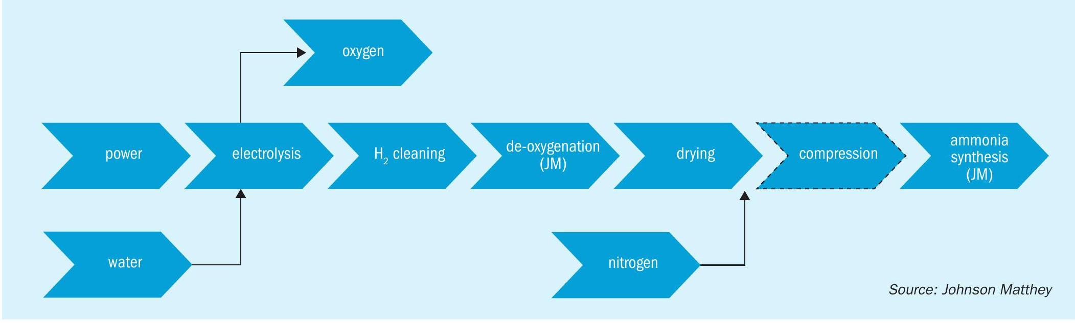
In the longer term, and particularly for ammonia production for the energy market, green ammonia production is in the best position to become the dominant technology. Reductions in renewable energy costs, improvements in electrolyser technology, higher natural gas prices recently in much of the world and the drive to reduce carbon emissions mean that green ammonia is looking increasingly favourable as a viable alternative to traditional ammonia production technologies. The majority of projects in development are based on updated AWE (alkaline water electrolysis) or PEM (proton exchange membrane) type electrolysers, with a flowsheet similar to that shown in Fig. 1, a process schematic showing the building blocks of a typical green ammonia process.
One of the big considerations for these plants is how best to match the input power to the desired ammonia production rates. To effectively decarbonise the system the power generated must come from renewable or decarbonised energy production, but most renewable energy production methods have large fluctuations in output, for example wind and solar energy both fluctuate greatly depending on the weather. There are various methods in development to mitigate these effects, but despite this there will be more fluctuation in the flow of syngas to the synthesis loop compared to a conventional “grey” ammonia plant, so this will need to be factored into the design of the equipment in the loop to ensure that it is robust and adaptable to these conditions.
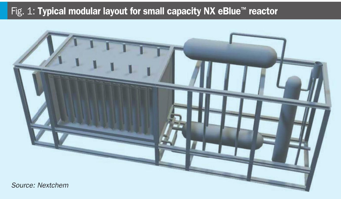
The green ammonia technologies in development fall into two major categories – designs with high pressure synthesis loops and those that have low pressure ammonia synthesis at the electrolyser operating pressure. The low-pressure plants tend to be at a smaller scale or modular in design, with multiple modules to achieve the desired capacity. The high-pressure plants may also have a modular approach in terms of the electrolysis section, with the potential to add more capacity over time but they have a large ammonia synthesis loop operating at high pressures (from 130 to over 300 barg). Some of the projects focussing on the smaller/modular plants are designing for ammonia production at the operating pressure of the PEM electrolyser to reduce the need for compression. These projects are looking at ammonia synthesis at significantly lower pressures than existing large scale ammonia production, from some as low as 20 barg to around 45 barg, with relatively low conversion per pass of ammonia in the synthesis reactor due to the less favourable equilibrium conditions.
A study carried out by the University of Cambridge looked into the potential for using integrated reaction and absorption in a single vessel for green ammonia synthesis production and separation, with the absorbent to remove product ammonia and reduce the impact of equilibrium on the ammonia production rate2 . As part of this work, various catalysts were tested at low temperatures and pressures (220-400°C, 20 barg) to look at the operating conditions that may be seen on small scale green ammonia units. At these conditions it was found that, on a volumetric basis, KATALCO 74-1 showed comparable reaction rates to the ruthenium-based catalyst they were testing and actually exceeded the ruthenium catalyst at lower temperatures.
For the high synthesis pressure type designs the conditions within the loop are similar to conventional ammonia plants or with even higher pressures so the reaction equilibrium is relatively good and conventional catalysts are suitable for this duty, with KATALCO 74-1 GREEN a superior choice to deliver high performance in the centralised synthesis loops.
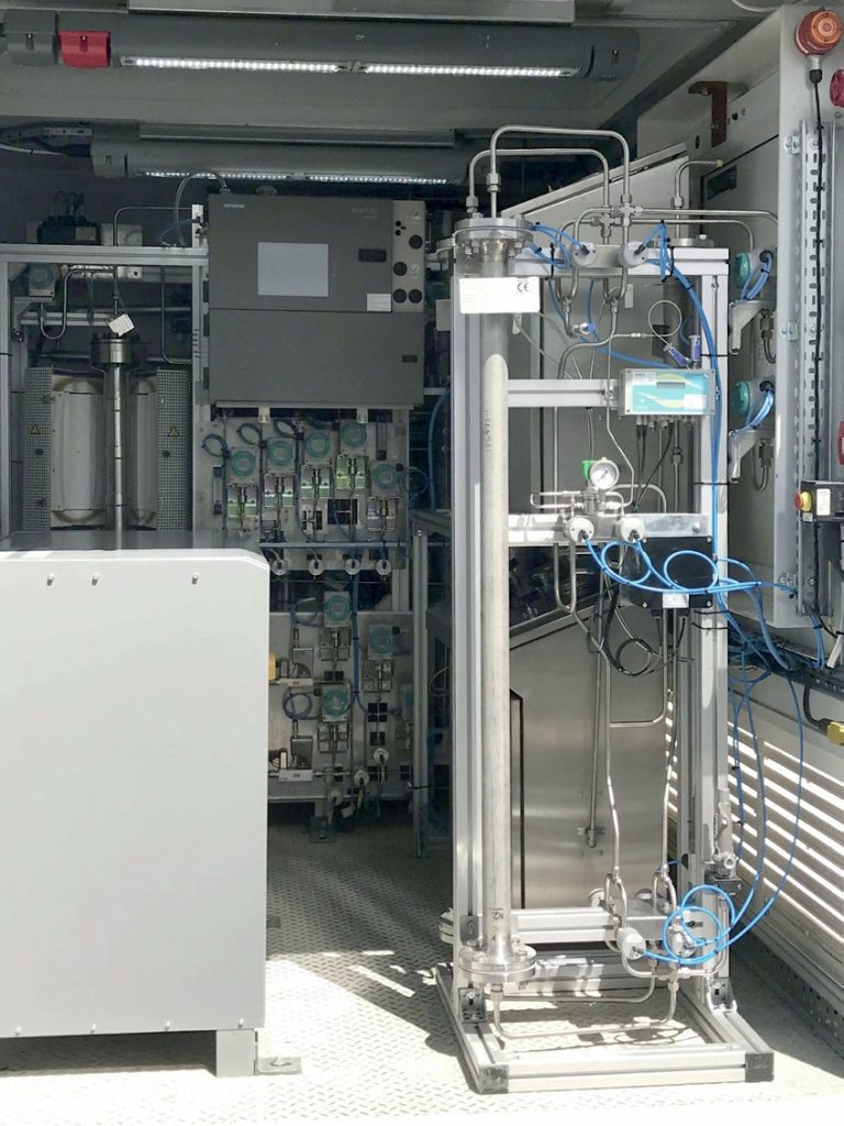
In the UK as part of National Net-Zero Project a Green Ammonia Demonstrator was designed, built and commissioned at the Science & Technology Facilities Council (STFC) Rutherford Appleton Laboratory in Oxfordshire in 2018. This unit was loaded with JM’s high activity KATALCO 74-1 GREEN ammonia synthesis catalyst. The aim of the project was to be a small-scale demonstrator for the world’s first roundtrip application of green ammonia for energy storage (power-to-ammonia-to-power). The project was part of the Siemens-led Decoupled Green Energy project and is now entirely operated by STFC.
ASPIRE, a UK government funded project headed by STFC in collaboration with The University of Bath, Johnson Matthey and Frazer Nash Consultancy, is a project to build a 150 kW green ammonia demonstration plant (also to be located at the Rutherford Appleton Laboratory), powered by a combination of solar PV panels and a wind turbine. Due to the nature of the renewable energy generation the power input to the plant will vary considerably with changing wind and sun conditions and it is being designed for flexible generation. The unit comprises a PEM electrolyser and PSA nitrogen generator feeding into an ammonia synthesis loop with a three-bed, quench-cooled reactor, installed with KATALCO 74-1 GREEN catalyst. There is a Smart battery in the flowsheet, but it is relatively modest in scale and the plant is being designed for high turn down rates and transient operation such that the ammonia generation tracks the intermittent renewable power. Unlike many of the other smaller scale plants the ammonia synthesis reactor within this unit is designed to operate at more conventional operating pressures of approximately 100 bar.

To assess the viability of ammonia synthesis at the low pressures associated with many of the small, modular green ammonia units in development, testing of KATALCO 74-1 GREEN catalyst was undertaken down to pressures of 25 barg. This testing and associated modelling confirmed that KATALCO 74-1 GREEN still shows high activity at these low pressures and Johnson Matthey’s in house models provide a good measure of the reaction dynamics even in this operating envelope. Due to the low pressures the equilibrium conversion is significantly lower than in conventional ammonia synthesis reactors so the outlet ammonia concentration from the reactor is lower (likely <10 mol-% NH3 ) and a higher recycle rate would be necessary compared to the higher pressure loops.
High activity KATALCO 74-1 catalyst
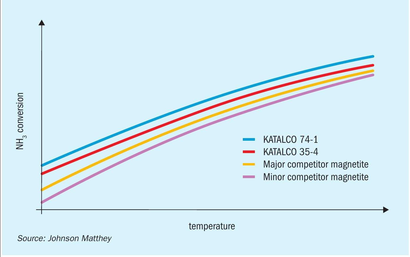
KATALCO 74 series high activity catalysts were initially developed for used in the AMV and LCA processes, as the low pressure (80 bar) synthesis benefitted from a more active catalyst. As this increased activity compared to conventional magnetite catalysts is applicable over the whole range of ammonia synthesis converter pressures however, more recently it has been adopted for high pressure synthesis loops along with the lower pressure applications. This increase in activity, illustrated in Fig. 3, and an increased ease of reduction are achieved by incorporation of cobalt oxide as a promoter and differing re-optimised levels of the other structural and electronic promoters compared to standard magnetite catalysts. The cobalt has the effect of increasing the rates of nitrogen adsorption and ammonia desorption from the surface of the catalyst, hence increasing the rate of the overall synthesis reaction.
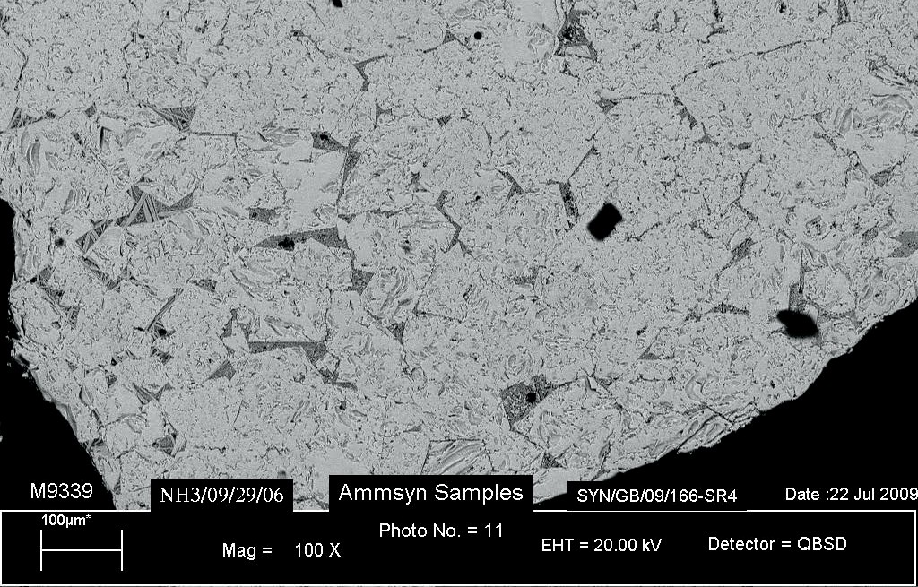
A number of studies3-6 into the location of cobalt in ammonia synthesis catalysts have looked at the reasons for the positive effect on catalyst reduction and activity. In these studies, cobalt oxide is found as a solid solution dissolved in the magnetite phase. The incorporation of cobalt into the iron lattice distorts the structure of the fused iron catalyst, generating layers of cobalt spinels which typically produce smaller iron crystallites on reduction, as shown in Fig. 4, benefitting the catalyst activity.

This catalyst is robust and stable, with the high activities relative to conventional magnetite catalysts sustained over long catalyst lifetimes. Johnson Matthey has a long list of references for these KATALCO 74 series catalysts, all showing high activities maintained for long lifetimes with a number of plants operating for over 20 years on the same charge. LCA plants were designed to have a more flexible loop than conventional ammonia plants, so whilst not as variable as some of the new green ammonia plants are designed to be the catalyst within these LCA plants has coped with more transient operation in terms of temperatures and pressures than in more conventional loop designs and proved stable.
Revamps of existing plants
The scope for low carbon solutions via revamps is dependent on the final product manufactured on the site – if the ammonia is fed to a urea plant then the majority of the carbon dioxide recovered in the CO2 removal stage will be used as feedstock for urea production. In this case there is potential for carbon capture and storage (CCS) only from the flue gas exit the primary reformer and any surplus CO2 not required for urea production. If the plant is producing merchant ammonia or the site is manufacturing ammonium nitrate, etc. then more of the carbon can be captured and sequestered with potential CCS on both the flue gas from the primary reformer and the CO2 stream from the CO2 removal stage. Concurrently with installing CCS technology many plants will look to make other improvements during a revamp project including debottlenecking and opex reductions, where a high activity ammonia synthesis catalyst such as KATALCO 74-1 can be utilised in conjunction with other upgrades to get the most out of the plant. Some plants have also added additional capacity by installing an electrolyser to feed clean hydrogen into the front end of an ammonia plant, to partially reduce the emissions from the plant and enable the producers to charge more for this proportion of green ammonia. More substantial increases in capacity in this way are likely to require further alterations/uprates to the rest of the plant to enable effective operation.
Summary
Reducing the carbon footprint of ammonia plants is not without its challenges, but the increased focus on the development of green and blue ammonia flowsheets and technology, along with changes in the market and legislation have made these plants increasingly commercially viable. Whilst blue ammonia plants are more viable in the short term for large scale production for fertilizer production the choice of end product can affect the scope for carbon footprint reduction. For green ammonia, whilst the development of this technology has decreased the production cost, the majority of the scope for this cost reduction is around the design and intensification of the electrolysers. However, use of the high activity KATALCO 74-1 GREEN catalyst in these flowsheets can aid in optimisation of the loop and subsequently bring operating costs down. For the green ammonia flowsheets with low pressure loops, KATALCO 74-1 GREEN catalyst has been tested down to 25 bar internally and even lower still in the University of Cambridge study and it still shows reasonable activity even at these low pressures. The ASPIRE project is developing a green ammonia demonstration unit, feeding power from local renewable energy generation to show that generation of ammonia from a variable renewable power source is achievable.
References