Sulphur 409 Nov-Dec 2023

30 November 2023
Sulphur plant revamps to meet future challenges
SRU REVAMPING
Sulphur plant revamps to meet future challenges
M. Rameshni and S. Santo of Rameshni & Associates Technology & Engineering (RATE USA) discuss some of the many solutions available to revamp sulphur plants to meet stricter environmental regulations with regard to SO2 and CO2 emissions. RATE technologies for the ultimate goal of achieving near zero SO2 emissions and World Bank requirements are also illustrated.
The revamp of existing sulphur plants to meet future challenges can be categorised into several scenarios including CO2 removal, SO2 emission reduction, and impacts of IMO with regard to both CO2 and SO2.
CO2 recovery from facilities, including sulphur plants, is one of the hot topics that the oil and gas industry is focussing on to reduce the emission of greenhouse gases such as CO2 from the atmosphere. A number of different separation technologies can be employed for post-combustion capture or pre-combustion capture. They include:
- adsorption;
- physical absorption;
- chemical absorption;
- cryogenics separation
- membranes:
- RATE combination of membrane and CO2 liquefaction.
SO2 emission reduction requirements vary around the world. The United States and Europe are required to meet SO2 emission targets ranging from 250 ppmv to less than 50 ppmv depending on the local regulations. The World Bank has also set an SO2 emission requirement of less than 50 ppmv for funding new investments which translates to a recovery of 99.99%. A three-stage Claus unit can meet a sulphur recovery rate of 95-97%. Some facilities are looking for a robust, simple and reliable solution to increase the sulphur recovery rate with minimum investment, minimum shutdown period, minimum or no training and no pre-investment for recovery beyond 97% or 99.5%. A number of solutions are discussed in this article:
- Changing the typical Claus catalysts to more advanced formulated catalysts could increase the sulphur recovery from 97% up to 99.5% and will meet such regulations with minimum modifications to the existing units. RATE offers two catalysts SMAX-100 and SMAXB-100 for selective oxidation of H2S to sulphur and selective reduction of SO2 to sulphur.
- Adding a tail gas treating unit (TGTU) with an amine section to a two- or three-stage conventional Claus unit can reduce SO2 emissions to between 100 ppmv and 250 ppmv depending on the amine solvent selection.
- Adding RATE’s TG-MAX technology: In the TGTU after the hydrogenation reactor, a hydrolysis reactor is added to maximise the hydrolysis of COS and CS2 and to minimise the SO2 emission. The vent gases from the sulphur pit, degassing and the sulphur storage tank are collected and recycled back to the reaction furnace of the SRU.
- Adding RATE’s SETR process to increase sulphur recovery beyond 99.5% without the need for conventional tail gas treating: SETR is located after the incinerator and before the stack and can be applied after any type of TGTU.
- A caustic scrubber can be added after the thermal incineration and before the stack. This scheme is widely used and is an alternative scheme to SETR.
- Adding a sulphuric acid plant after the sulphur recovery unit will reduce SO2 emissions and produce sulphuric acid which has many uses within a facility.
- Adding RATE’s Catalytic Tail Gas Incineration (CTI) or Catalytic Tail Gas Incineration MAX (CTI-MAX). The SO2 can be treated by using a caustic scrubber, or by using ammonia to produce ammonium sulphate as a useful product.
Meeting IMO regulations using different levels of oxygen enrichment: IMO 2020 mandates a maximum sulphur content of 0.5% in marine fuels globally. The additional sulphur compounds shall be removed from the upstream units before the sulphur recovery unit to meet the new regulations. In addition, for lean acid gas some level of oxygen enrichment could help to improve the sulphur recovery.
CO2 recovery options1
Decarbonisation options including pre-post and post combustion CO2 removal in SRUs were discussed previously in Sulphur no. 404. The required energy for CO2 removal is very important where CO2 is produced to remove the CO2. It is crucial to carefully evaluate the CO2 removal case by case and to select the most economical option.
RATE has filed a patent application with the US Patent Office that covers the combination of CO2 recovery and hydrogen generation in SRUs (not yet published).
Recently, RATE has been working on a project for CO2 recovery and SO2 emission control in Europe. Fig. 1 provides an example showing how CO2 and SO2 emissions can be reduced.
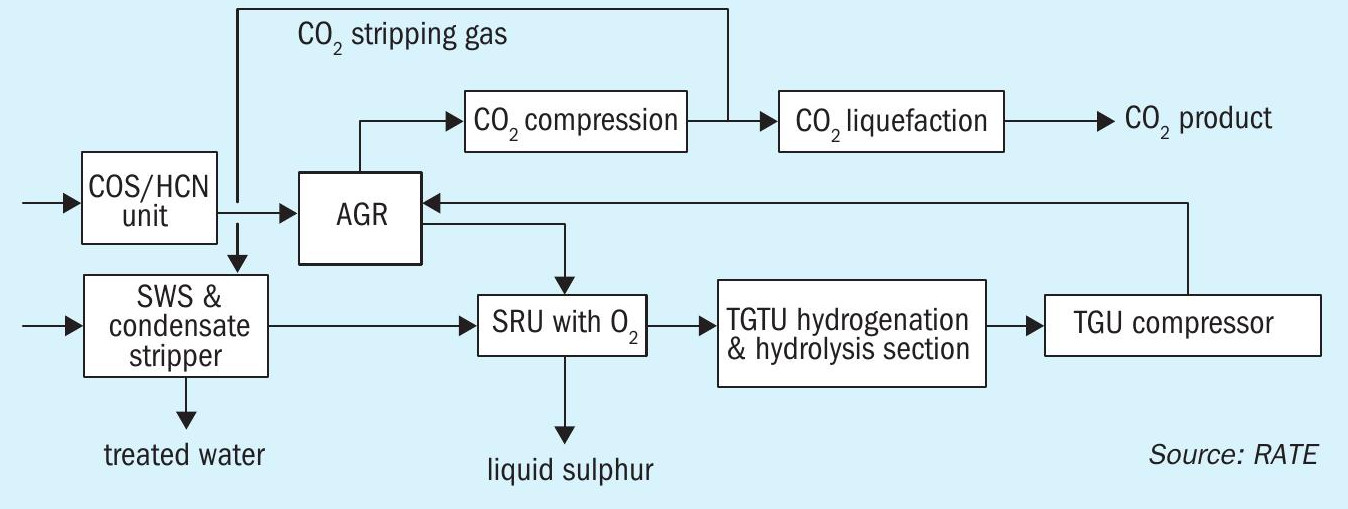
The main RATE technologies employed are as follows:
- CO2 liquefaction unit – using CO2 liquefaction instead of an amine type unit is very economical and the required energy is significantly reduced;
- Two-stage sour water stripper (with H2S absorber);
- COS hydrolysis reactor in the tail gas unit (an additional reactor after hydrogenation reactor);
- SRU oxygen enrichment.
SO2 emission reduction options
Controlling SO2 emissions is one of the critical challenges that many countries are trying to overcome to meet their local environmental regulations. In some cases, reducing emissions requires a higher energy consumption which requires a significant increase of the operating costs.
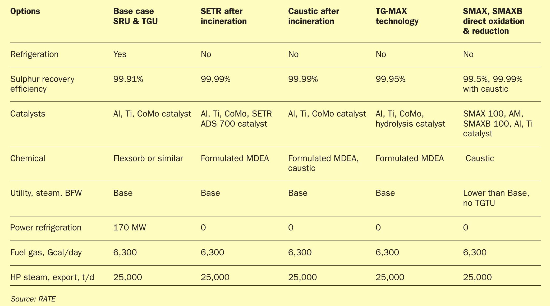
RATE conducted a feasibility study in the Middle East, where they usually operate larger sulphur plants and due to the hot climate, the energy consumption is very high. In this study, the customer had an existing regular Claus unit and was looking for options to reduce SO2 emissions with optimised energy consumption and reasonable operating and capital costs.
One of the biggest concerns was that if they were to use a chiller to cool the quench water and the amine circulation, it would require 170 MW electricity, which would result in an electricity operating cost of several million dollars per month.
As shown in Table 1, the chiller could be eliminated with significant cost savings, while also reducing SO2 emissions and increasing the sulphur recovery efficiency. The customer should be able to select the revamp option based on local regulations and avoid additional unnecessary investment.
ACT (Advanced Clean Technology) SO2 emission summary
Table 2 provides a summary of the typical SO2 emissions for the implementation of different schemes.
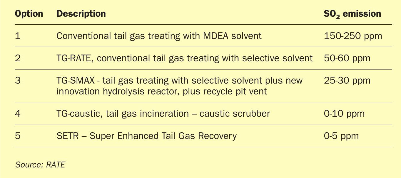
Other sulphur recovery schemes like sub dew point processes were not discussed because the revamp options 2–5 in Table 2 can be applied to any type of sub dew point process to achieve the desired emission according to local environmental regulations. The sub dew point process recovery range is from 98.5% to 99.5%.
There are some basic actions that can be taken to increase the recovery and to improve the operation as follows:
- Use a high intensity SRU burner for better destruction of ammonia, hydrocarbons and impurities.
- Use titanium catalyst at the bottom of the first SRU reactor bed and alumina at the top. The volume of the Ti catalyst could be up to 50% of the total catalyst volume.
- Recycle the vent gas from the sulphur pit and sulphur degassing, which is traditionally routed to the incinerator, to the front of the SRU. It is very important that the recycle gas is routed to the proper location to prevent any cold spots or plugging as well as any impact on the SRU recovery.
- Select formulated amine solvent instead of generic MDEA in the tail gas unit to achieve 10 ppmv of H2S from the absorber overhead.
Increasing sulphur recovery with advanced catalysts2
There are still many countries that do not require very tight SO2 emissions but are nevertheless looking for a sulphur recovery rate of above 98%. RATE SMAX and SMAXB technology is a patented technology (US Patent US 9,023,309 B1), which offers schemes based on advanced catalysts.
Short descriptions of the retrofitting of existing SRU modifications from some current projects are listed below: l Retrofitting existing two-stage Claus to 2+1 SMAX: requires adding a third reactor (with selective oxidation catalyst) to the existing two-stage Claus SRU. Most of the work can be done as add-on, skid-mounted units with no need to shut down, however, tie-in of the third reactor, piping, instruments, utilities, etc. requires approximately two weeks of unit shutdown and will improve the sulphur recovery efficiency from 95% to 99% or 99.1% depending on the H2 S concentration.
- Retrofitting existing two-stage Claus to 3+1 SMAX: requires adding a third reactor (with conventional Claus catalyst) and a fourth reactor (with selective oxidation catalyst) to the existing two-stage Claus SRU. Again, most of the work can be done as add-on, skid-mounted units with no need to shut down, however, tie-in of the third and fourth reactors and associated piping, instruments, utilities, etc. requires two to three weeks of unit shutdown and will improve the sulphur recovery efficiency from 95% to 99%-99.4%.
- Retrofitting existing two-stage Claus to keep 2 + 1 SMAX: requires changing the catalyst in the second existing reactor (with combined conventional Claus + reduction catalyst) and adding a third reactor (with selective oxidation catalyst) to the existing two-stage Claus SRU. Again, most of the work can be done as add-on, skid-mounted units with no need to shut down, however, tie-in of the third reactor and associated piping, instruments, utilities, etc. requires three to four weeks of unit shutdown and will improve the sulphur recovery efficiency from 95% to 99.2%-99.3%.
- Use a high intensity SRU burner for better destruction of ammonia, hydrocarbons and impurities.
- Use titanium catalyst at the bottom of the first SRU reactor bed and alumina at the top. The volume of the Ti catalyst could be up to 50% of the total catalyst volume.
- Recycle the vent gas from the sulphur pit and sulphur degassing, which is traditionally routed to the incinerator, to the front of the SRU. It is very important that the recycle gas is routed to the proper location to prevent any cold spots or plugging as well as any impact on the SRU recovery.
- Select formulated amine solvent instead of generic MDEA in the tail gas unit to achieve 10 ppmv of H2S from the absorber overhead.
Increasing sulphur recovery with advanced catalysts2
There are still many countries that do not require very tight SO2 emissions but are nevertheless looking for a sulphur recovery rate of above 98%. RATE SMAX and SMAXB technology is a patented technology (US Patent US 9,023,309 B1), which offers schemes based on advanced catalysts.
Short descriptions of the retrofitting of existing SRU modifications from some current projects are listed below:
- Retrofitting existing two-stage Claus to 2+1 SMAX: requires adding a third reactor (with selective oxidation catalyst) to the existing two-stage Claus SRU. Most of the work can be done as add-on, skid-mounted units with no need to shut down, however, tie-in of the third reactor, piping, instruments, utilities, etc. requires approximately two weeks of unit shutdown and will improve the sulphur recovery efficiency from 95% to 99% or 99.1% depending on the H2 S concentration.
- Retrofitting existing two-stage Claus to 3+1 SMAX: requires adding a third reactor (with conventional Claus catalyst) and a fourth reactor (with selective oxidation catalyst) to the existing two-stage Claus SRU. Again, most of the work can be done as add-on, skid-mounted units with no need to shut down, however, tie-in of the third and fourth reactors and associated piping, instruments, utilities, etc. requires two to three weeks of unit shutdown and will improve the sulphur recovery efficiency from 95% to 99%-99.4%.
- Retrofitting existing two-stage Claus to keep 2 + 1 SMAX: requires changing the catalyst in the second existing reactor (with combined conventional Claus + reduction catalyst) and adding a third reactor (with selective oxidation catalyst) to the existing two-stage Claus SRU. Again, most of the work can be done as add-on, skid-mounted units with no need to shut down, however, tie-in of the third reactor and associated piping, instruments, utilities, etc. requires three to four weeks of unit shutdown and will improve the sulphur recovery efficiency from 95% to 99.2%-99.3%.
- Retrofitting existing two-stage Claus to 3+1 SMAXB: requires adding a third reactor (with combined conventional Claus + reduction catalyst) and a fourth reactor (with selective oxidation catalyst) to existing 2-stage Claus SRU. Again, most of the work can be done as add-on, skid-mounted units with no need to shut down, however, tie-in of the third and fourth reactors and associated piping, instruments, utilities, etc. requires three to four weeks of unit shutdown and will improve the sulphur recovery efficiency from 95% to 99.2%-99.6%.
- In all four options listed above the H2 S-containing pit vent from the sulphur pit or degassing can be recycled to the front of the SRU instead of the incinerator to increase the sulphur recovery. It requires additional cost to recycle the pit vent stream.
In some cases, the third condenser and the fourth reheater after the SMAXB is eliminated as the SMAXB reactor provides an adequate temperature to the SMAX reactor.
Changing the catalysts and the number of required Claus reactors depends on the target desired sulphur recovery. In some cases three existing reactors may be adequate, in others a fourth reactor may be needed. Sometimes changing to SMAX 100 catalyst only may be adequate in the last Claus reactor but in other cases both SMAX 100 catalyst and SMAXB 100 catalyst may be required. It all depends on the feed stock to the sulphur recovery and the desired new local environmental regulations. It is therefore important to conduct a study before selecting the revamp option.
Conventional tail gas treating unit
The conventional tail gas treating unit includes a low temperature hydrogenation catalyst, quench system and the amine unit which many facilities around the world have already added to their sulphur recovery units. Some SRUs, mostly in the United States, have also added a caustic scrubber after the incinerator to meet the new World Bank SO2 emission requirements.
TG-MAX tail gas treating unit
TG-MAX can be added to the Claus Sulphur recovery unit as a new unit, or the conventional tail gas treating unit can be upgraded to TG-MAX (a RATE patented technology: US Patents US 10,752,502 B2 and US 9,624,106 B2).
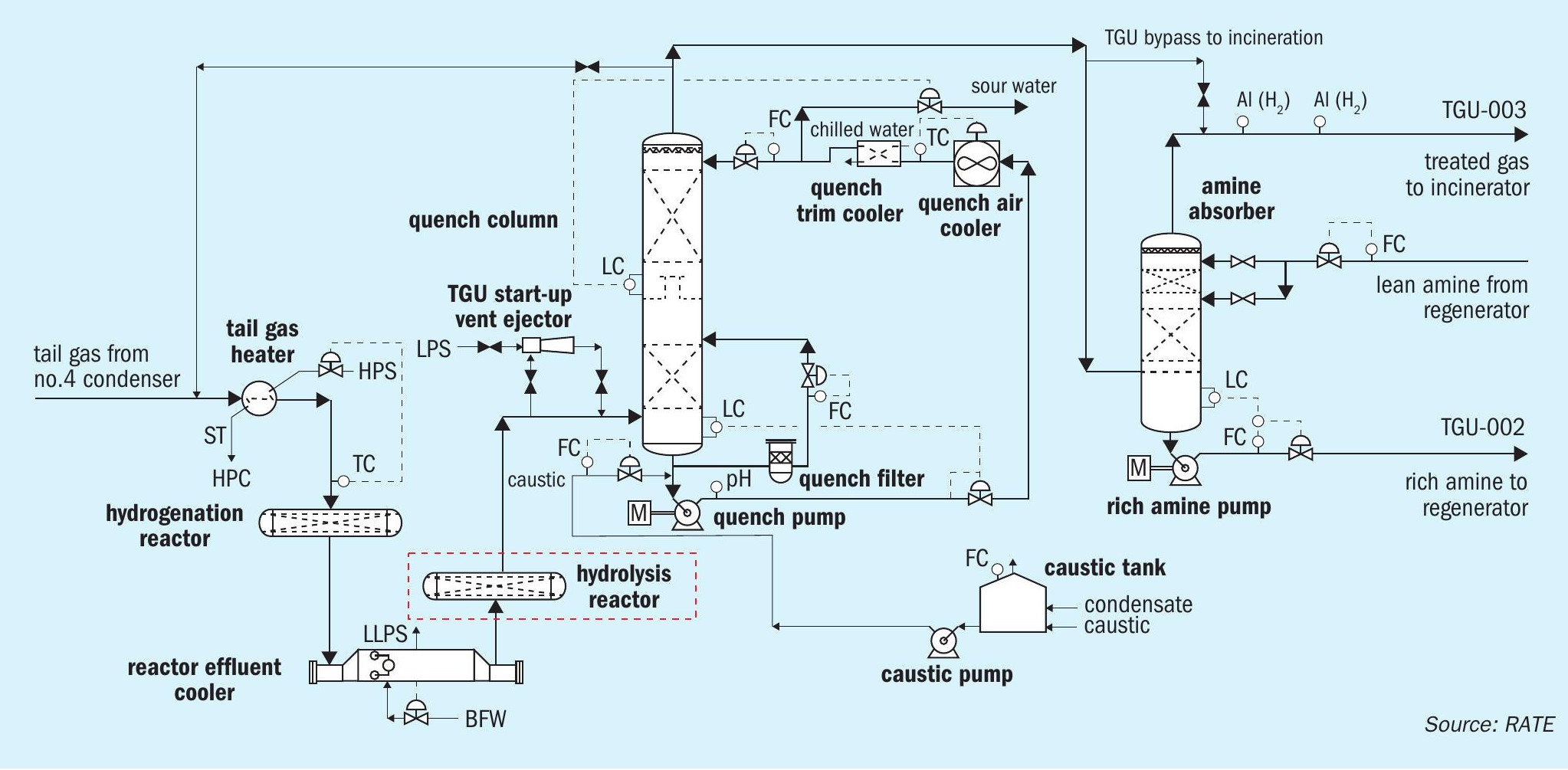
The RATE COS/CS2 hydrolysis reactor in the TGTU, is an additional reactor after the hydrogenation reactor to maximise the hydrolysis of COS and CS2 and to minimise SO2 emissions. It eliminates the caustic scrubber and spent caustic disposal after the incinerator. Fig. 2 represents TG-MAX with the hydrolysis reactor, and with pit vent recycled to the sulphur recovery reaction furnace.
The tail gas unit includes the hydrogenation reactor with low temperature hydrogenation catalyst. As part of the new invention an additional reactor is added, the so-called hydrolysis reactor, with both reactors in one shell to hydrolyse the remaining of COS and CS2 and any sulphur compounds. Based on actual operating data the amount of COS and CS2 is approximately 30 ppmv after the hydrogenation reactor.
As part of a new patented innovation, the remaining COS and CS2 is hydrolysed in the hydrolysis reactor. The gas is cooled and flows to the quench system where additional water is condensed before being processed in the tail gas amine unit using formulated selective solvent where the absorber overhead will have less than 10 ppmv of H2S.
Based on this scheme, the SO2 emission from the stack will be around 25-30 ppmv depending on the acid gas composition to the sulphur plant and how much COS and CS2 are produced and hydrolysed.
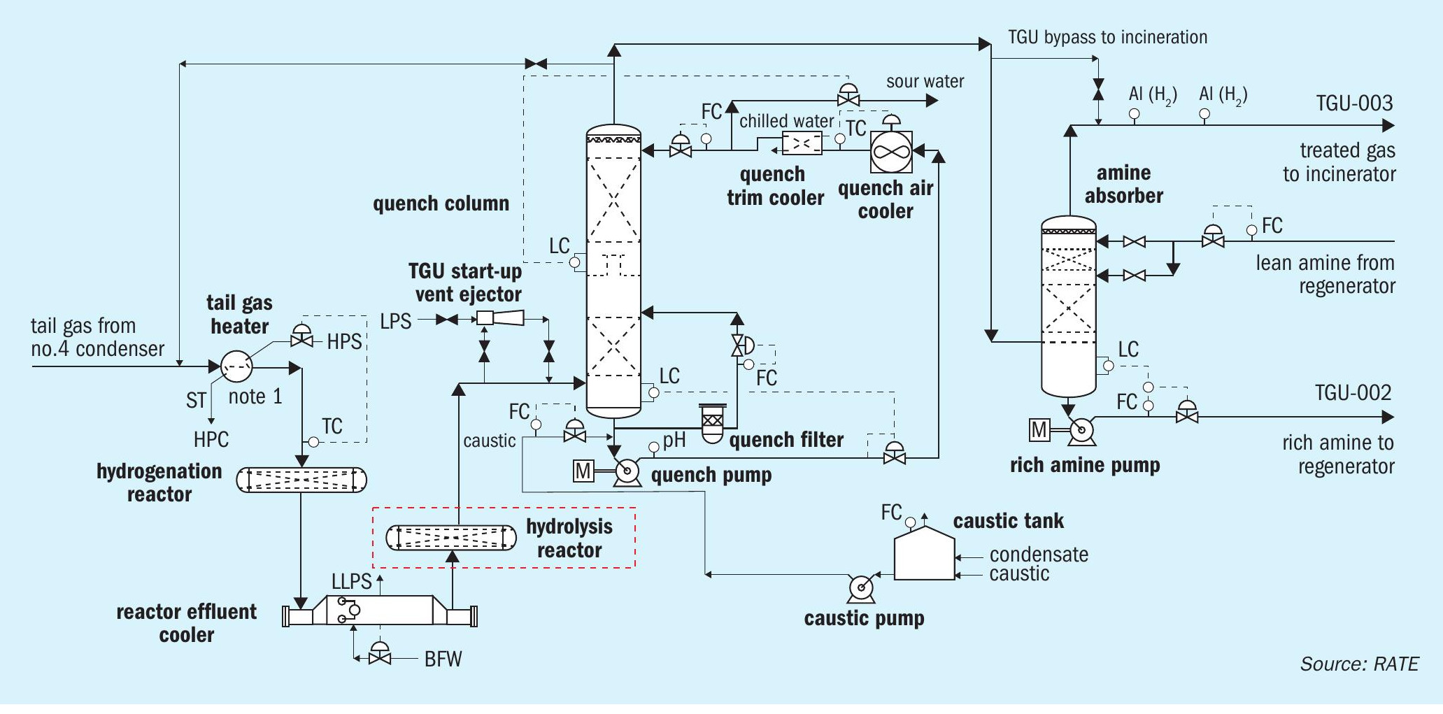
The sulphur pit vent and sulphur degassing vent are collected, the pressure is boosted and then recycled back to the SRU reaction furnace instead of incineration (Fig. 3).
Super Enhanced Tail gas Recovery (SETR) technology
SETR is another patented technology (US patent number US 10,689,254 B1) which is located after incineration and before the stack. It can be applied after any type of a tail gas treating unit to increase the sulphur recovery beyond 99.5%, without the need for conventional tail gas treating. Sulphur is recovered and recycled back to the SRU. In contrast to caustic scrubbing, which generates a waste stream, there is no waste stream from SETR. The SETR scheme will improve recovery efficiency from 99.5% to 99.9%-99.99%.
Retrofitting an existing two-stage Claus to SMAX / SMAXB plus SETR can achieve the ultimate sulphur recovery or zero SO2 emission.
The catalyst used in this process is SETR ADS 700, an activated alumina-based adsorbent with a catalyst life of four to five years, the same as Claus catalysts.
This process consists of the adsorbent and regeneration reactors. The SETR reactors switch between adsorption and regeneration modes. They are located after the tail gas incineration and before the stack replacing any type of the caustic scrubber system. The innovative SETR process is not a sub dew point process where the bed becomes saturated with sulphur, instead, the SETR process has fixed bed reactors that require heat up and cool down for the SO2 adsorption-based Claus tail gas process. The adsorption mode operates at a cold temperature to adsorb the SO2.
The SETR process is a cost competitive solution that converts unrecovered sulphur compounds to sulphur, without the need for chemicals, and without generating any waste streams.
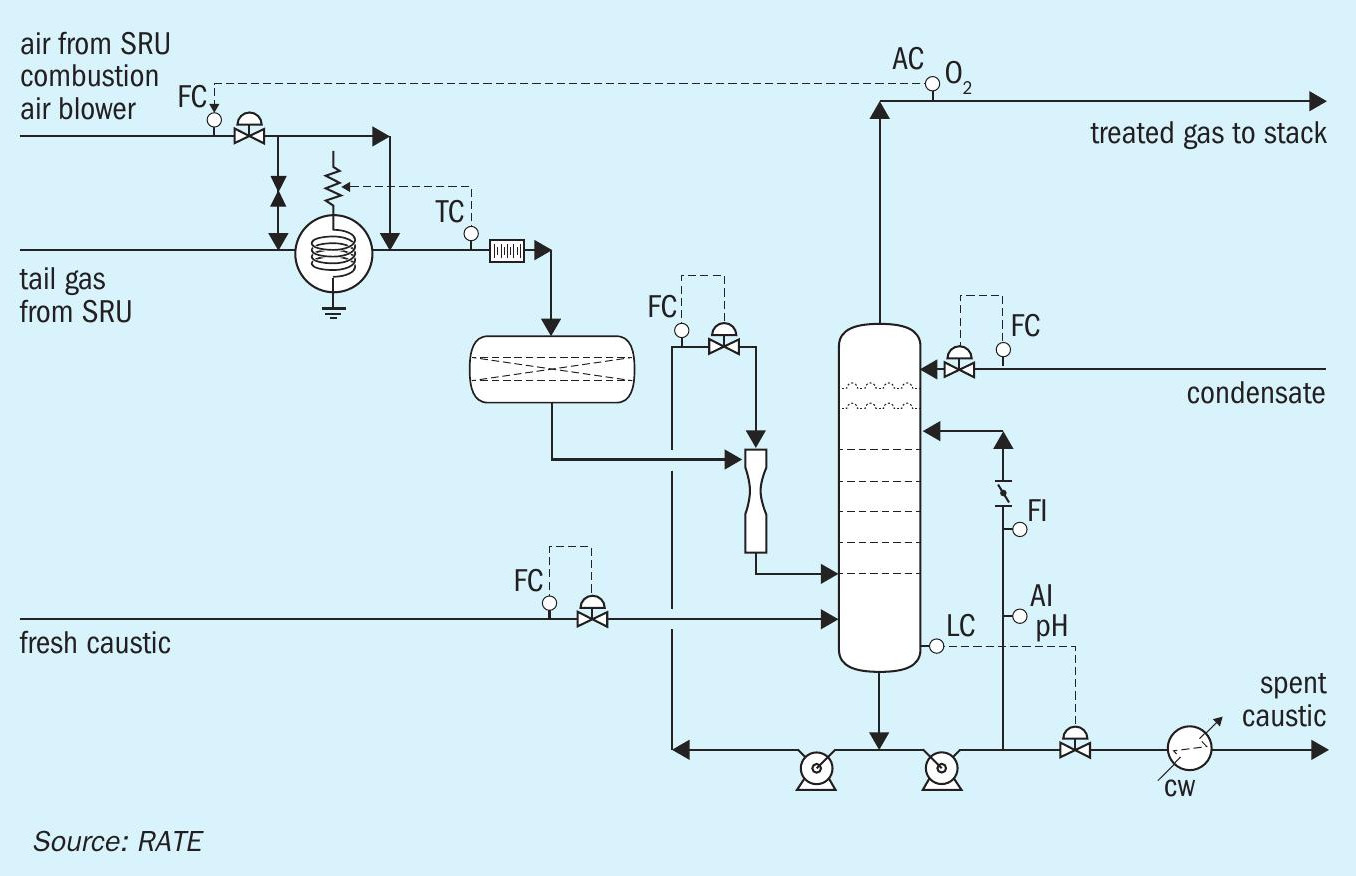
Tail gas thermal incineration with caustic scrubber
RATE is working with US government agencies that are mandating that existing operating SRU and TGUs control their SO2 emissions to meet 10 ppmv of SO2. RATE has been designing additional units for some of these projects and is supporting environmental regulation agencies in the US to control stack emissions in existing facilities. In some cases where the sulphur plant has no back-up tail gas unit, it is requested to install a caustic scrubber after the catalytic incinerator (Fig. 4).
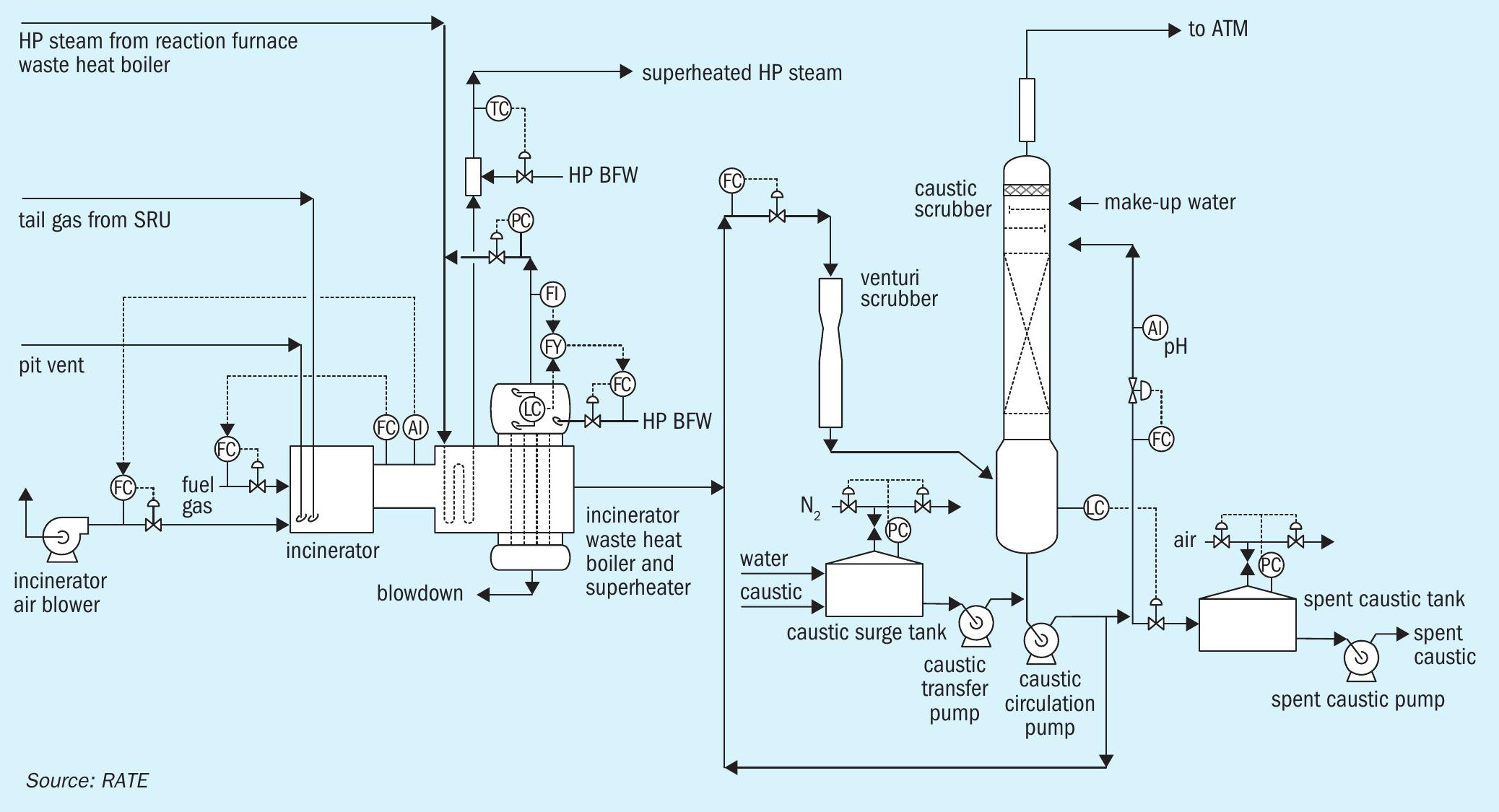
The waste caustic can be sent to the existing water treatment system or it can be neutralised and drained to a safe location.
The effluent gas from the thermal incinerator waste heat boiler is desuperheated in a venturi scrubber by intimate contact with a 10 wt-% caustic solution. During the liquid vapour contact a portion of the SO2 is removed from the vapour and the gas is cooled.
The liquid-vapour mixture then flows to the caustic scrubber. The vapour flows up through the packed bed of the caustic scrubber against a countercurrent stream of 10 wt-% caustic solution to scrub the remaining SO2 from the tail gas. The treated gas leaving the caustic scrubber will contain low ppm levels of SO2. With this scheme zero emission of SO2 (0-10 ppm) from the tail gas incineration can be achieved.
Sulphuric acid production
Sulphuric acid plants are well known in industry, mostly for the conversion of SO2 to acid in the following applications:
- sulphuric acid production & recycling;
- mining and roasting industry;
- viscose fibre industry;
- petrochemical industry;
- tail gas treating units (recent).
There are some refineries around the world that are able to produce sulphuric acid and to market the acid that is surplus to requirements for internal consumption.
In some new sulphur projects, tail gas units have been eliminated due to their high cost to achieve near 100% sulphur recovery and have instead been replaced by a sulphuric acid plant to eliminate SO2 emissions to the atmosphere.
In new refineries the concept of using a sulphuric acid plant as the tail gas treating plant allows any vent gas, or tail gas feed that contains sulphur compounds, to be routed to the acid plant.
In this option (see Fig. 5), the TGU amine unit and the incineration system is completely eliminated and the tail gas from the SRU is routed to the sulphuric acid plant. The vent gas from the sulphur pit and the sulphur degassing could be routed to the front of the SRU or to the sulphuric acid plant directly. An overall sulphur recovery of nearly 100% can be achieved.
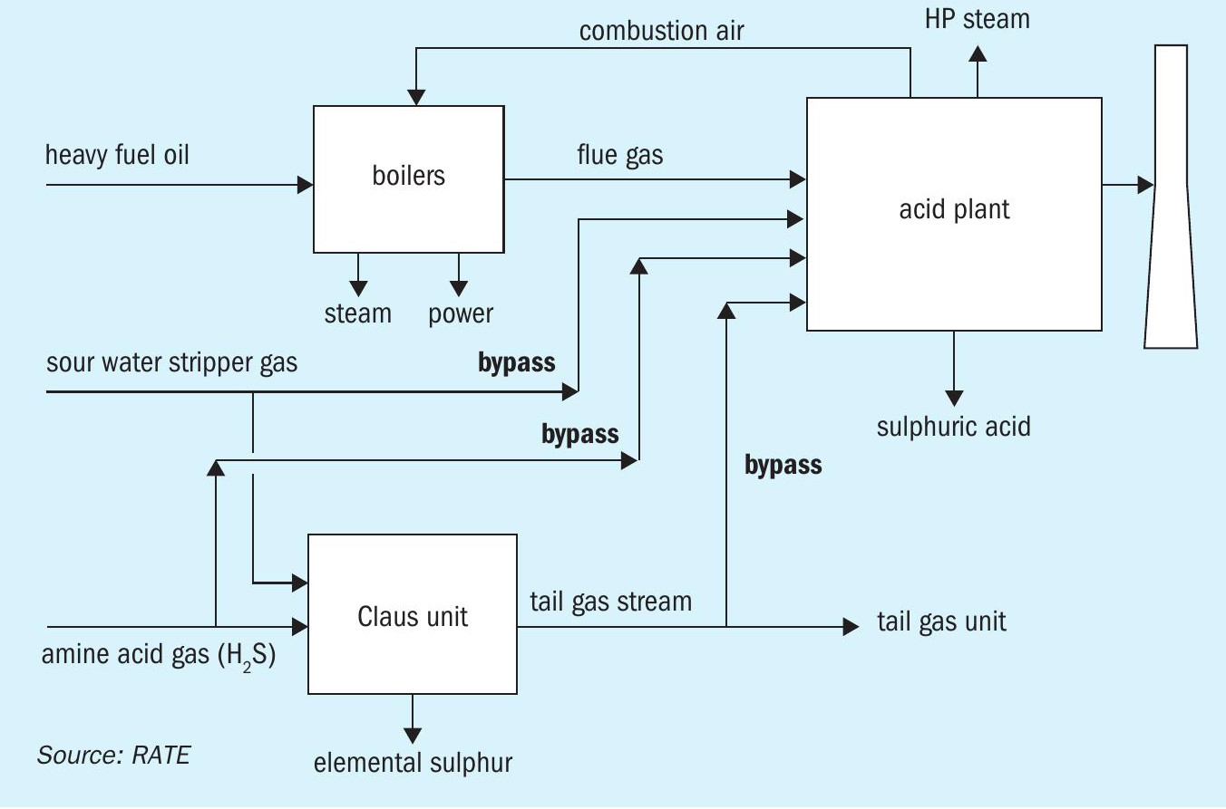
Another benefit of acid plant technology is if the refinery has to process crude with high nitrogen content. The sour water stripper ammonia gas may be beyond the capability of the sulphur plant but could be processed in the acid plant.
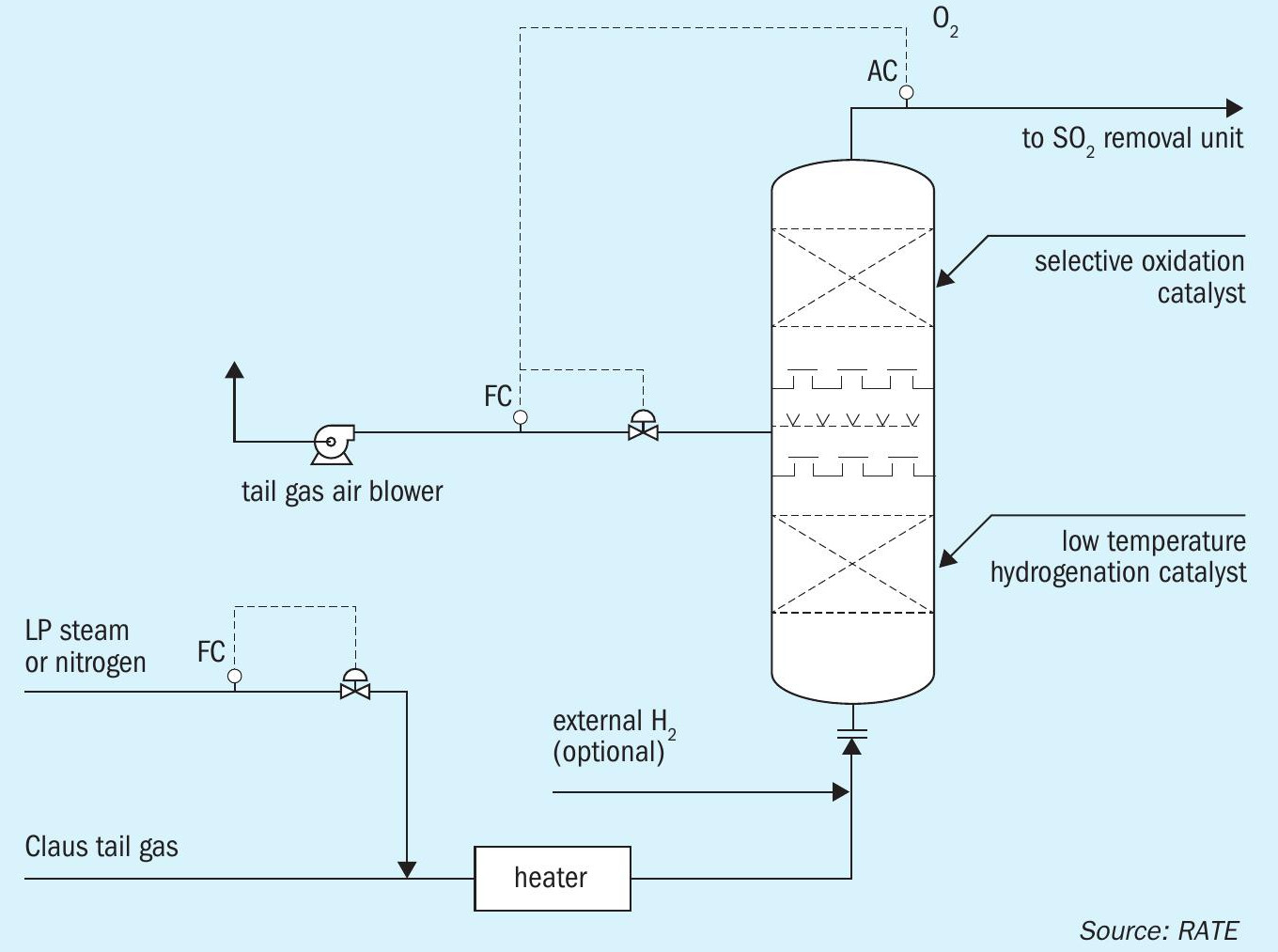
Catalytic tail gas incineration
Catalytic tail gas incineration (CTI) can also be regarded as a backup tail gas unit. Catalytic incineration can be used to reduce CO2 emissions and the fuel consumption of thermal incineration. In the past, RATE has designed its CTI unit with a caustic scrubber system, where less than 10 ppmv of SO2 could be met.
Recently RATE conducted a study to offer CTI-MAX in combination with the production of ammonium sulphate as a saleable product in a refinery application where pure ammonia was available. The existing sulphur recovery units were a three-stage Claus unit, and a three-stage Claus unit with direct oxidation similar to SMAX. Adding CTI-MAX and producing ammonium sulphate was attractive because both ammonia and SO2 could be used to make a saleable product.
RATE also licenses a two-stage sour water stripper which produces a high purity ammonia stream.
CTI-MAX is a catalytic tail gas incineration option which uses TGU low temperature catalyst and selective direct oxidation catalyst.
The gas leaving CTI-MAX can go to the incinerator or other units for processing SO2, such as a Cansolv unit or a caustic scrubber. Alternatively, if pure ammonia is available from a two-stage water stripper, ammonium sulphate or ammonium thiosulphate can be produced.
This process eliminates NG consumption from the conventional RGG by using an indirect heater, reduces fuel gas consumption in the incinerator, and reduces emissions.
Fig. 6 shows a schematic of CTI with a caustic scrubber and Fig. 7 shows a schematic of CTI-MAX.
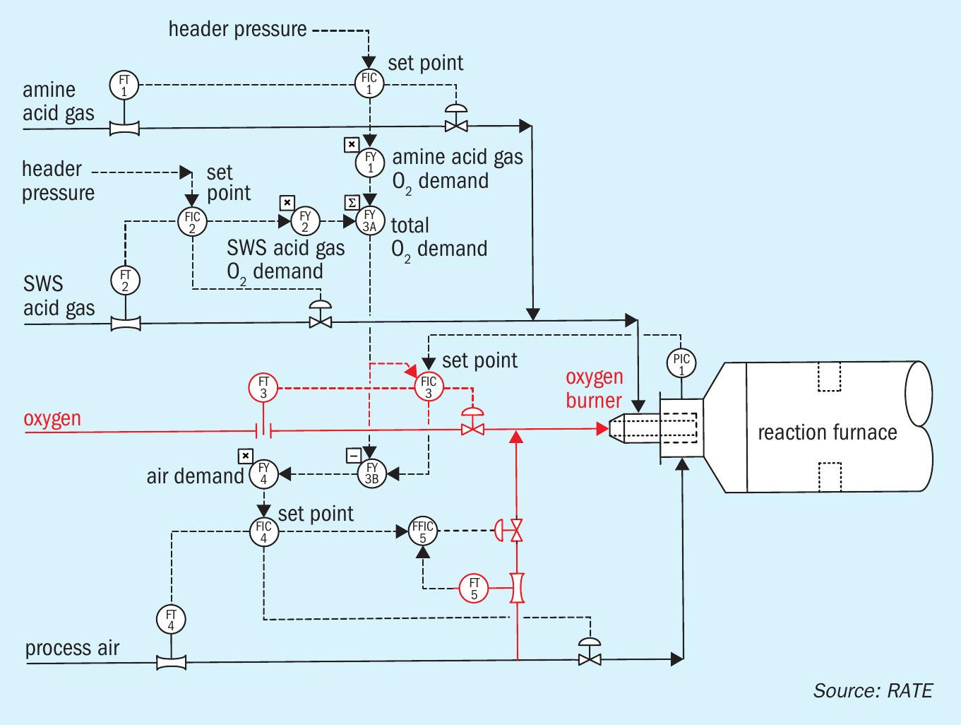
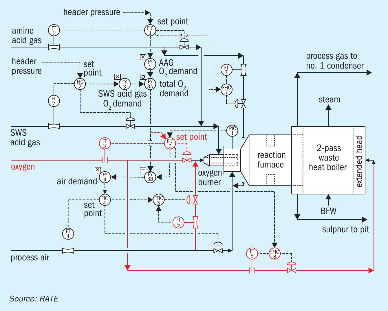
IMO Compliance with oxygen enrichment3
The results of implementing IMO 2020 globally means additional sulphur will be removed from other units and sent to the existing sulphur recovery units. Oxygen enrichment can be used to cope with the increased load to the SRU. Low to mid-level, and high level of oxygen enrichment can be implemented depending on the required additional capacity. In addition to capacity increase, oxygen enrichment can be used in lean H2 S applications to increase the recovery and to reduce CO2 and SO2 emissions.
Figs 8 and 9 show the control system and equipment modifications for using low to mid-level and high level of oxygen enrichment accordingly.
To comply with SO2 emissions, one of the schemes already discussed can be implemented.
Conclusions and summary
Sulphur plant revamps to meet future challenges fall into three main categories: CO2 removal, SO2 emission reduction, and compliance with IMO 2020.
There are many discussions taking place every day, in regard to CO2 removal but no particular solutions have been implemented.
With regard to SO2 emission reduction, there are still many countries, for example, Canada, Mexico, Russia, CIS region, part of the Middle East, among many others, that only have a three-stage conventional Claus unit and significant amount of SO2 is emitted through the stack. Therefore, focusing on reducing SO2 emission should be a priority. Local regulations vary from country to country and even in different regions and cities within a country. In most part companies are looking for solutions with minimum operating and capital costs, minimum shutdown during the revamp and no pre-investment. It is therefore important to evaluate each case carefully to select the best option to meet requirements.
In this paper, eight different solutions are recommended that result in different SO2 emission levels. RATE technologies for the ultimate goal of achieving near zero SO2 emissions and World Bank requirements are also illustrated, for example, TG-MAX Technology specially for large gas plants dealing with very large existing sulphur plants.
Finally, IMO regulations will result in additional sulphur to the sulphur recovery unit. Oxygen enrichment can be implemented as part of a revamp to accommodate the additional capacity in existing SRUs and is also one of the recommended solutions for reducing SO2 emission levels.
References