Nitrogen+Syngas 387 Jan-Feb 2024
31 January 2024
An ideal reactor for green methanol
GREEN METHANOL
An ideal reactor for green methanol
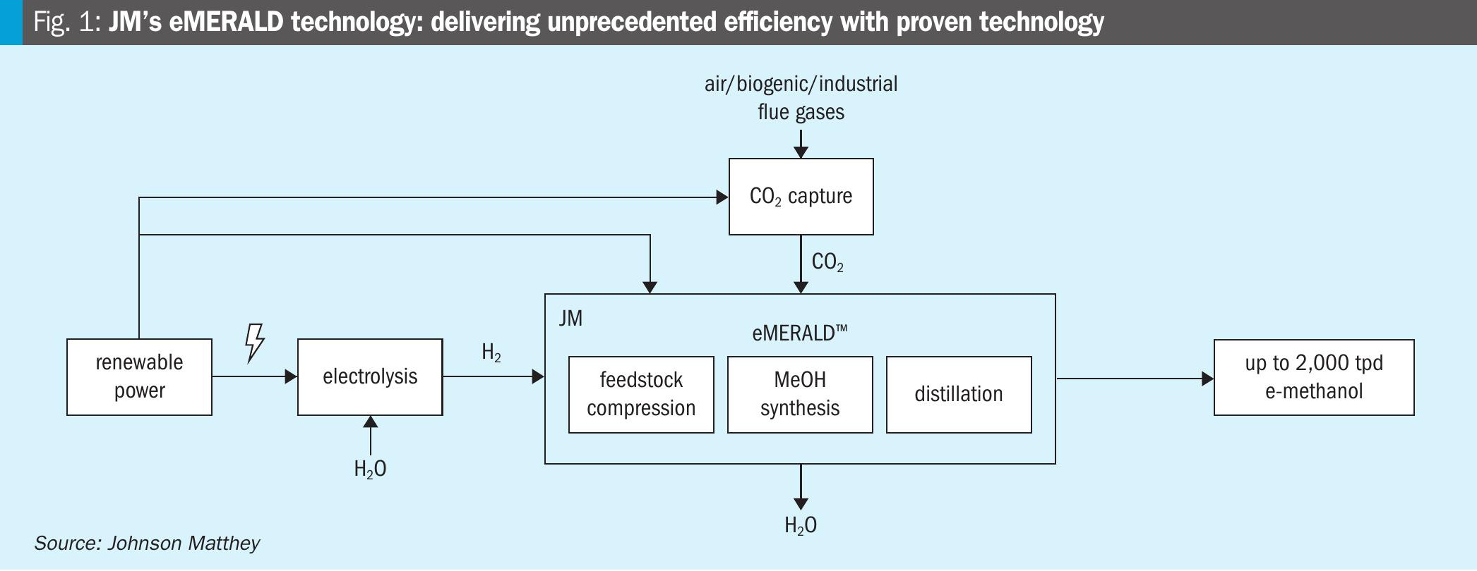
As the production of renewable methanol continues to scale up, it will provide a long term, carbon-neutral energy solution to different transport sectors. However, the optimum design parameters for green methanol plants are substantially different to natural gas-based methanol plants and pose new challenges to the methanol loop designer. Connor Longland of Johnson Matthey (JM) discusses the challenges and presents the benefits of the tube cooled converter for e-methanol production.
Today, methanol is mainly produced from synthesis gas obtained from fossil fuels, but it can also be manufactured from sustainable sources. As the production of renewable methanol continues to scale up, it will provide a long term, carbon-neutral energy solution to different transport sectors. Methanol can be made by direct hydrogenation of carbon dioxide (CO2) with renewable hydrogen (H2). This production route mitigates the amount of CO2 released into the atmosphere and offers a low-carbon alternative to conventional transportation fuels if it is produced by sustainable feedstocks, such as electrolytic hydrogen and carbon dioxide from waste streams of biological origin.
Hydrogen and carbon dioxide as feedstocks for green methanol production place different optimisation demands on designers compared to traditional plants based on syngas.
Natural gas-based methanol plants are based on the production of syngas by steam methane reforming in an endothermic process. The syngas produced is then fed into the methanol synthesis loop. Historically, refined methanol has benefitted from low natural gas prices that have allowed methanol synthesis loops on natural gas-based plants to run at syngas efficiencies in the range of 85-90%, with the unconverted purge gas being used as fuel in the steam methane reformer (SMR). Based on a typical natural gas consumption of 34GJ/t methanol and natural gas prices in the range of $3 per GJ, traditional merchant grade methanol historically trades in the range $300-400 per tonne1 .
The optimum design parameters for green methanol are substantially different because feedstock costs are much higher. To illustrate this, the typical energy consumption of a highly efficient green methanol process, including the expected energy demand to generate the electrolytic hydrogen, is around 11.5MWh/t methanol. Assuming a renewable electricity price of $30 per MWh2 , this brings the cost of methanol production based on electricity alone to $375/t. Furthermore, the fact that there is no natural home for the purge gas stream from the methanol synthesis loop means it is desirable for purge flows to be minimised as much as practicably possible.
This poses new challenges to the methanol loop designer and critically shifts the optimisation focus on to maximising the hydrogen and carbon dioxide conversion into product methanol.
Fundamentals of the CO2 to methanol reaction
Methanol synthesis from carbon oxides (COx) and hydrogen is an equilibrium reaction favoured by low temperatures and high pressures. A typical methanol process is operated at 80 bara pressure with peak reaction temperatures of 280°C. At these conditions, the maximum methanol concentration at the outlet of the converter is around 14 mol-%. Therefore, as the per pass conversion of synthesis gas to methanol is limited by equilibrium, in order to achieve high conversion, the methanol synthesis section is arranged as a loop, recycling unreacted syngas, as in the example shown in Fig. 1.

In the CO2 to methanol process, the carbon dioxide and hydrogen feed gas are mixed to achieve the desired stoichiometric ratio and compressed up to the pressures necessary for methanol synthesis. Unconverted syngas is separated from the methanol product by condensation and the unconverted syngas is recompressed and sent back to the methanol reactor for another pass. A purge is taken to control the build-up of inerts and fresh syngas feed is added in to achieve the required methanol production.

As Table 1 illustrates, the syngas feed into the methanol synthesis loop is significantly different in a CO2 to methanol plant compared to a conventional natural gas or coal based methanol plants. Most notable is the difference in the CO:CO2 ratio, which can be very low depending on the composition of the CO2 waste stream.
The heat of reaction for conversion of carbon dioxide to methanol is approximately half of that of carbon monoxide as shown in the enthalpies for the two reactions below:
CO2 + 3H2 → CH3 OH + H2 O -49.5 kJ/mol
CO + 2H2 → CH3 OH -90.6 kJ/mol
As a result, the heat released in the methanol converter with pure carbon dioxide and hydrogen feeds is lower compared to the traditional synthesis feed gas compositions.
For syngas-based plants with high CO:CO2 ratios, the heat of reaction needs to be managed by either a high heat removal efficiency or by limiting the per pass conversion and increasing the circulation ratio. The low CO:CO2 ratios mean that the converter heat removal duty is lower, thus rendering the selection of converter type to be disconnected from the requirement for a high heat removal efficiency.
Moreover, the catalyst volumes required to achieve the same methanol production rate are greater for a CO2 to methanol duty than for traditional syngas feeds. This is because the CO2 has a slower rate of reaction and requires larger catalyst volumes than the CO reaction to methanol. An additional parameter leading to increased catalyst volumes is the potential for higher catalyst sintering rates in a CO2 to methanol duty, due to the higher level of water formation in the reaction products.
The most critical parameter in the design of an e-methanol synthesis loop, however, is the recycle ratio (RR). This is the ratio between the flow of circulating gas at the outlet of the circulator and the flow of fresh make-up gas (MUG):
RR = (total gas to converter -MUG)/MUG
The higher the circulation ratio, the higher the feedstock efficiency and therefore the lower the variable production costs associated with generating the feedstock. With the price of renewable power dominating the methanol production cost, the circulation ratio becomes one of the most crucial factors affecting the levelised cost of methanol production.
Based on Fig. 2, the selection of the 100 ideal converter type for CO2 to methanol 10 duty should take into account the requirement 0 for higher circulation ratios, 1,000 as 900 well as 800 for accommodating more catalyst volume per reactor. On the other hand, the reactor used does not necessarily have be as efficient in heat removal as would be required for a traditional syngas-based methanol synthesis loop.

Methanol reactor design
There is a new set of demands for reactors employed in CO2-to-methanol duty for the production of e-methanol: the need to maximise feedstock efficiencies on one hand, and the absence of a suitable process option to make use of the purge gas fuel on the other.
Based on the above requirements, operating plants at high circulation ratios is preferred. To better illustrate this, a comparative study was carried out to determine the optimum circulation ratio for synthesis loops based on a tube cooled converter (TCC) and the most commonly used axial steam raising converter (ASRC), shown in Figs 3 and 4 respectively.


What is the optimum circulation ratio?
This study considers a typical CO2 to methanol plant with a capacity of 300 t/d.
Carbon dioxide and hydrogen are fed to the plant at 10 bar a, where they are mixed and compressed (as shown in Fig. 5). The syngas then passes to the methanol synthesis loop where it is reacted to form methanol. The crude methanol exits the loop and enters a three-column distillation train which refines the methanol to product grade. To control the build-up of inerts, a small purge is taken from the synthesis loop and passed through a hydrogen recovery unit (typically a membrane unit) which recovers 85% of the hydrogen and recycles it back to the front end. The remaining purge gas is exported OSBL.

In order to better illustrate the impact of feedstock efficiency on operating cost, hydrogen consumption has been translated to an electrolyser power demand.
Although the level of inerts in the feed and H2 /CO2 ratio of the make-up gas also influence loop efficiency, these two parameters are assumed to be constant.
In carrying out the study the following assumptions were used:
- 300 t/d production
- hydrogen and carbon dioxide feed pressure at 10 bar a;
- 85% H2 recovery in the hydrogen recovery unit (HRU);
- 98.5% distillation efficiency; l hydrogen produced by electrolysis with an energy input requirement of 5 kWh/ kNm3/hr;
- carbon dioxide feed conditions and composition assumed as typical from a carbon capture source.
Firstly, the effect of recycle ratio on the overall energy consumption for the TCC and ASRC-based loops was calculated and is shown in Fig. 6. The overall energy consumption is calculated as the total plant energy demand, including pumping/ compression duties and electric process heating, plus the energy requirement for the generation of the hydrogen feed.

The results show that at low recycle ratios, which are typical for ASRC loops, the total power demand for the e-methanol plant is around 0.6 to 0.7 MWh/tonne larger than the high circulation cases that are characteristic of TCC-based synthesis loops. This is because, despite the low circulator power at low recycle ratios, the lower loop efficiencies mean that more power is required to both generate and compress the feed gases into the loop.
Depending on the performance of the HRU membrane, the minimum power consumption is achieved for circulation ratios in the range of 4-5, that translates to a methanol concentration at the exit of the converter of between 4.5-5%. These parameters are within the typical operating range for a TCC.
The TCC reactor can therefore easily adjust to the demands of the new CO2 – based process because the optimum circulation ratio for CO2 duty is closely aligned with the TCC’s optimum operating parameters from natural gas operation.
Conversely, this is not the case for the ASRC. The penalty for operating at the traditional circulation ratio of 2 for an ASRCbased loop is 6% higher energy consumption when compared with the high circulation (<4 RR) alternative, equating to an energy consumption of 12.2 MW/t methanol.
As shown in Fig. 6, in order to improve the process economics, the ASRC loop needs to operate at the same high circulation ratios that the TCC has traditionally operated at. However, as you operate at higher circulation ratios the per-pass conversion drops, meaning less reaction heat is generated in the converter and the advantages of having good heat transfer properties and raising steam become diminished.
Additionally, because of pressure drop limitations, the way to facilitate an increase in the circulation ratio is to increase the diameter of the ASRC. This increases the size of an already relatively heavy converter, from the point of view of reactor weight per tonne of methanol production. An increase in the diameter of an ASRC converter would also entail an increase in the thickness and diameter of the tube sheet resulting in additional fabrication costs and complexity.
As plants become larger and the diameter increases, the thickness of tube sheets means that the overall weight of the ASRC makes it impractical to achieve the required duty in a single ARSC reactor. Due to the limitations in the diameter of an ASRC tube sheet design, it is not possible to design a single axial loop to function at capacities larger than 1,000 t/d whilst operating at high circulation ratios (see Fig. 7). A second converter would be therefore required to achieve efficient operation at high capacities, increasing the capital cost requirements of the plant when compared with a single TCC loop, which has high circulation operating references up to ~2,500 t/d.

Operational flexibility
JM believes the tube cooled converter and the high circulation loop is well placed to cope with fluctuating feed rates and the potential increase in the frequency of start-ups/shutdowns predicted for a plant based on renewable power.
The catalyst kinetics and heat removal calculations for these reactors have been developed by JM over the last 40 years, with excellent correlations between modelled and real plant data. The only adjustment the operator needs to make is to adjust the inlet temperature to maximise methanol production as the catalyst ages. Turndown can be managed through adjusting the circulation rate and inlet temperature, which can be automated through a capacity management system.
The TCC is resilient to changes in operating conditions characteristic of high rates of turndown, as the tops of the tubes are open and not constrained by a tube sheet, removing any concerns about differential thermal expansion of the tubes relative to the shell. Having catalyst on the shell side also reduces the risk of damaging the catalyst through radial tube expansion.
Conclusions
The optimum design parameters for a CO2 to methanol plant are significantly different to those considered when designing a conventional syngas-based methanol loop. Consequently, the advantages that an axial steam raising converter can offer for syngas-based designs are not applicable for CO2-to-methanol duties. At small capacities the benefits from the generation of steam are diminished and the presence of a steam system can be capex intensive, whilst at large capacities, the ASRC-based loops either suffer from inefficiencies due to operating at low circulation ratios or induce higher capital investment, as the mechanical design necessitates the specification of multiple converters at higher circulation rates.
The TCC reactor is considered to be the ideal choice for e-methanol plants, as it avoids the requirement for a high-pressure steam system, especially attractive for low capacity plants. In addition, the mechanical design of the TCC is well suited to high circulation ratios and the operational flexibility requirements of a green methanol plant dependant on renewable energy sources for feedstock generation. Finally, the TCC has a long history of efficient operation at high circulation ratios, meaning established optimum operating parameters can be utilised to maximise feedstock efficiencies and minimise operating costs.
References