Sulphur 414 Sep-Oct 2024

30 September 2024
Enhancing sulphuric acid production
CASE STUDY
Enhancing sulphuric acid production
In this case study, Florian Kistl of CS Combustion Solutions presents a comprehensive strategy for the capacity enhancement and optimisation of a sulphuric acid production plant that was facing several operational challenges that were hindering its efficiency and reliability. As a result of a series of targeted optimisations, including the innovative use of ultrasonic nozzles and CFD modelling, downtime and maintenance costs were reduced, and a substantial capacity increase was achieved.

Sulphuric acid production is a critical process in various industrial sectors. This particularly applies to mining, where H2SO4 is extensively used for a wide range of applications. In the mining industry, H2SO4 plays a pivotal role in processes such as leaching of copper, cobalt and precious metals. In this beneficiation process it is used to extract these metals from their ores. Additionally, it is used in the production of phosphoric acid, which is essential for manufacturing fertilizers, and in the descaling of equipment to remove mineral deposits, ensuring the smooth operation of mining machinery.
As demand for sulphuric acid continues to rise across these industries, plants must find ways to increase output while minimising operational expenditures (opex) and maintenance requirements.
This article discusses a case study involving a sulphuric acid plant located in the African Copperbelt region, where significant upgrades have been implemented to boost production capacity from 2,200 t/d to 3,000 t/d. The measures taken by CS Combustion Solutions, including the use of ultrasonic nozzles and advanced combustion technologies, played a pivotal role to support the plant in achieving these goals.
Challenges before optimisation
The sulphuric acid plant faced several issues that hindered its performance and efficiency. These challenges included incomplete combustion of sulphur, leading to sulphur droplets reaching the waste heat boiler (WHB) ferrules and catalyst beds. This not only caused fouling but also increased the overall pressure drop, causing unplanned shutdowns for cleaning and maintenance. The previously used pressure atomisers contributed to these problems by causing frequent nozzle plugging, which required costly and time-consuming replacements. Additionally, the plant’s refractory lining suffered from hot spots, which most likely are also caused from bad atomisation quality.
Together with the plant management, CS identified the following key challenges:
Incomplete combustion due to pressure atomisers: Resulting in sulphur droplets contaminating downstream equipment (fouling).
Nozzle plugging and wear: Frequent stoppages due to nozzle issues, increasing downtime.
Pressure drop and overheating: Inefficient combustion, high droplet size and inappropriate refractory design leading to operational inefficiencies and hot spots.
High maintenance costs: Frequent part replacements and the inability to perform maintenance without stopping production, increased operational costs. According to operators data the consumption of nozzle tips and guns summed up to > $200,000 in less than two years of operation.
Uneven temperature distribution: Chamber design and pressure atomiser principle led to hot spots and overheating of the outer shell (see Fig. 2).
CS Combustion Solutions’ approach
To address these issues, CS Combustion Solutions proposed and implemented a comprehensive revamping and optimisation strategy. The key measures included:
Ultrasonic nozzle atomisation: The replacement of traditional pressure atomisers with ultrasonic nozzles significantly improved the atomisation quality. The droplet size could be reduced from 400 µm to 110 µm, enhancing the efficiency of sulphur combustion and minimising the risk of fouling in the waste heat boiler and catalyst beds as well as wear on the refractory material
Swirl bodies for enhanced combustion: The introduction of swirl bodies into the combustion system induced rotational motion in the combustion air. This modification promoted optimal flame formation, resulting in more efficient and complete combustion of sulphur and oil (in start-up case).
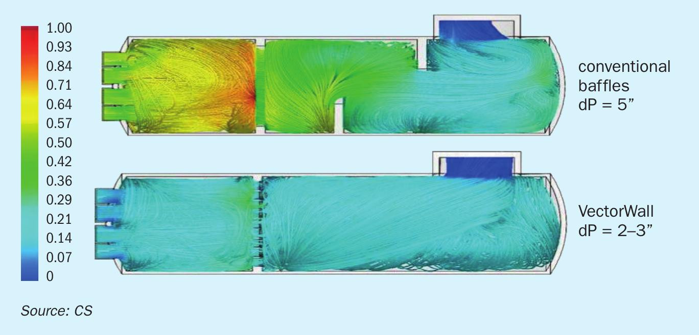
Single vector wall installation: The originally installed baffle walls, which introduced insufficient turbulence and increased the overheating effect caused by bad atomisation quality, were replaced with a single vector wall. This innovation ensured superior mixing within the combustion chamber, preventing unreacted sulphur from carrying over into downstream processes (see Fig. 3).
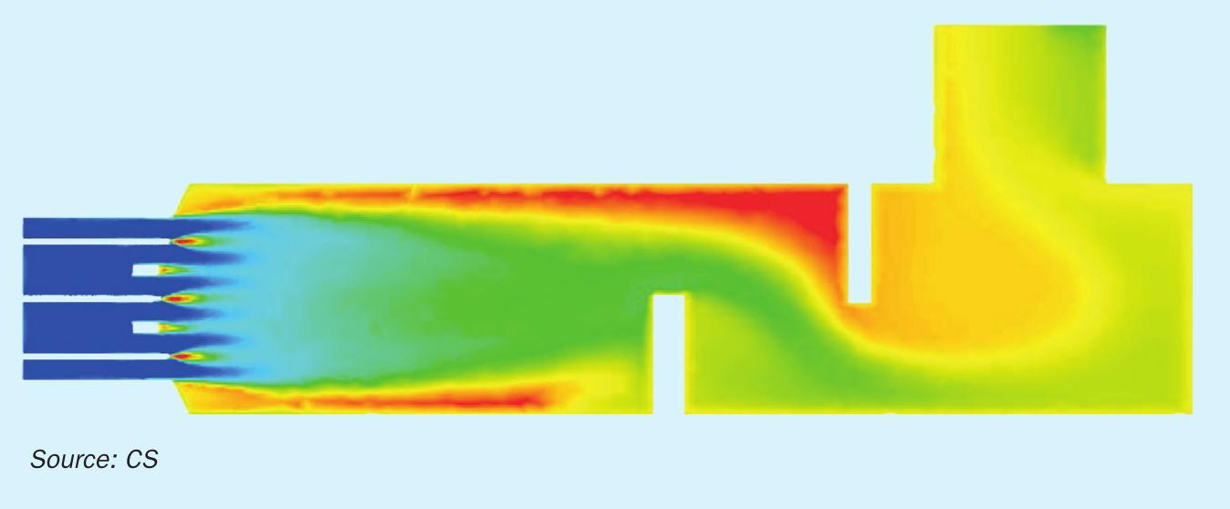
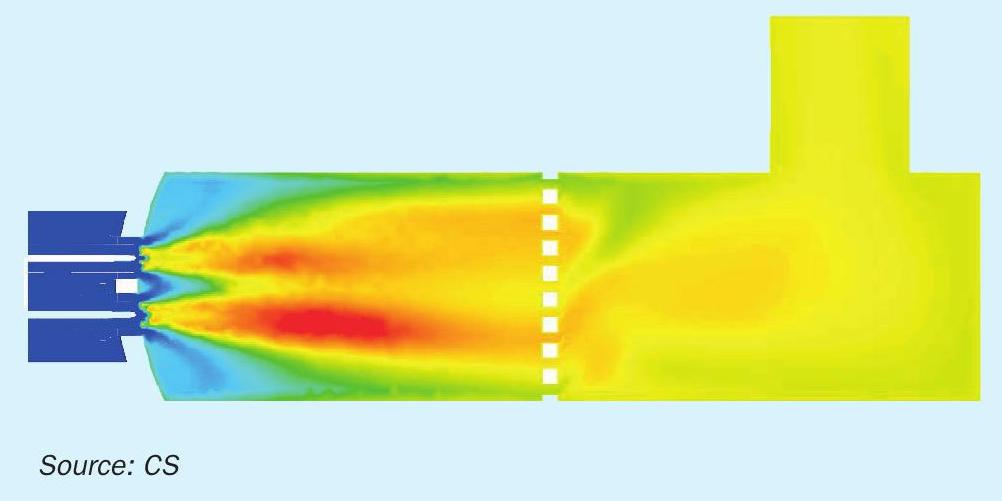
Computational fluid dynamics (CFD) study: A CFD study was conducted to calculate, visualise, and optimise the proposed changes before their implementation. This step was crucial, ensuring that the modifications would yield the desired improvements in performance and reliability. Fig. 4 shows the temperature distribution inside the furnace after the CS revamp.
Results and benefits
The implementation of these measures led to significant improvements in plant performance and operational efficiency. The most notable outcomes included:
Increased production capacity: The plant’s capacity was successfully increased by 30%. This resulted in the incineration of 40 tonnes of sulphur per hour, corresponding to 3,000 t/d of sulphuric acid.
Improved maintenance flexibility: The ability to change out sulphur guns during operation without shutting down the plant resulted in reduced downtime and higher overall productivity.
Enhanced combustion efficiency: The use of swirl bodies and ultrasonic nozzles improved SO2 conversion time, leading to more complete combustion and lower emissions despite reduced residence time after capacity increase.
Reduced pressure loss: The new combustion chamber design with the vector wall significantly reduced pressure loss, leading to opex savings on blower operations by $160,000/year.
Elimination of hot spots: The improved and controllable atomisation angle of the ultrasonic nozzle prevents big sulphur particles on the refractory, enhancing the operational life time and safety of the furnace.
These improvements not only enhanced the plant’s operational efficiency but also reduced the frequency of unplanned shutdowns, resulting in substantial cost savings. The strategic use of advanced combustion technologies and thorough pre-implementation analysis provided a robust framework for optimising sulphuric acid production.
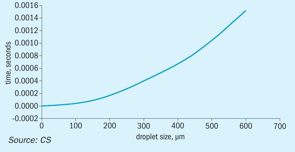
Fig. 5 shows the relation between droplet size and time needed for conversion for sulphur to sulphur dioxide.
Conclusion
This success story can provide valuable insights for similar facilities facing comparable challenges. It underscores the importance of high atomisation quality/low droplet size to minimise stress on downstream equipment. Ultrasonic nozzles by CS Combustion Solutions are a quick and easy upgrade on existing furnaces.