Sulphur 415 Nov-Dec 2024
30 November 2024
The importance of cryogenic distillation technologies
DECARBONISATION
The importance of cryogenic distillation technologies
As the oil and gas industry focus on new requirements for CO2 recovery, cryogenic processes come under the spotlight. Mahin Rameshni and Stephen Santo of RATE USA discuss the importance of cryogenic processes in acid gas sweetening. Liquefied H2S and CO2 reinjection is proposed as a cost effective alternative to large sulphur plants.
Acid gas streams, consisting primarily of hydrogen sulphide (H2S) and carbon dioxide (CO2), are commonly generated as a by-product of the gas sweetening process used to bring gases up to pipeline specifications for sales and transport. The conventional method for acid gas disposal is to have an acid gas sweetening unit to produce the sales gas and to use a Claus process to convert the H2S to sulphur. However, new requirements for CO2 recovery will add further costs to these projects.
In a typical sour gas field development with high H2S content, the common practice is to produce a large quantity of sulphur. However, in order to meet pipeline sales gas quality, dehydration, hydrocarbon dew point control, nitrogen rejection, NGL and LPG recovery are required, for which cryogenic distillation is applied. New requirements call for additional CO2 recovery from the stack, so-called flue gas decarbonisation which could refer to CO2 liquefaction as one of the options which is also a cryogenic process and the most economical option.
The concept of CO2 recovery and reinjection is expanded to both H2S and CO2 recovery and reinjection, which, ultimately would meet the emission requirements for both sulphur and carbon. The reinjection of H2S and CO2 can be optimised using an advanced cryogenic process.
It is well known that reinjection of H2S and CO2 in a gas phase requires large compressors to inject the gases deep underground. Safety aspects, H2S leakage and large compressor stations are some of the cost factors to be considered. However, by using a cryogenic process, the H2S and CO2 can be converted into the liquid phase, allowing pumps to be used for reinjection, which brings a number of benefits:
- pumping a low pressure liquid is a lot less risky than compressing a high pressure gas;
- the advantage of having high concentration H2S is that it can be more easily liquefied;
- putting the highest pressures underground under a wellhead is more reassuring from a safety manageability point of view.
RATE offers cryogenics technologies for the following applications:
- H2 S and CO2 liquefied reinjection;
- CO2 liquefaction and reinjection;
- hydrocarbon dew point control;
- NGL Recovery and LPG Product;
- cryogenic nitrogen rejection;
- cryogenic helium recovery;
- SO2 liquefaction with or without a membrane.
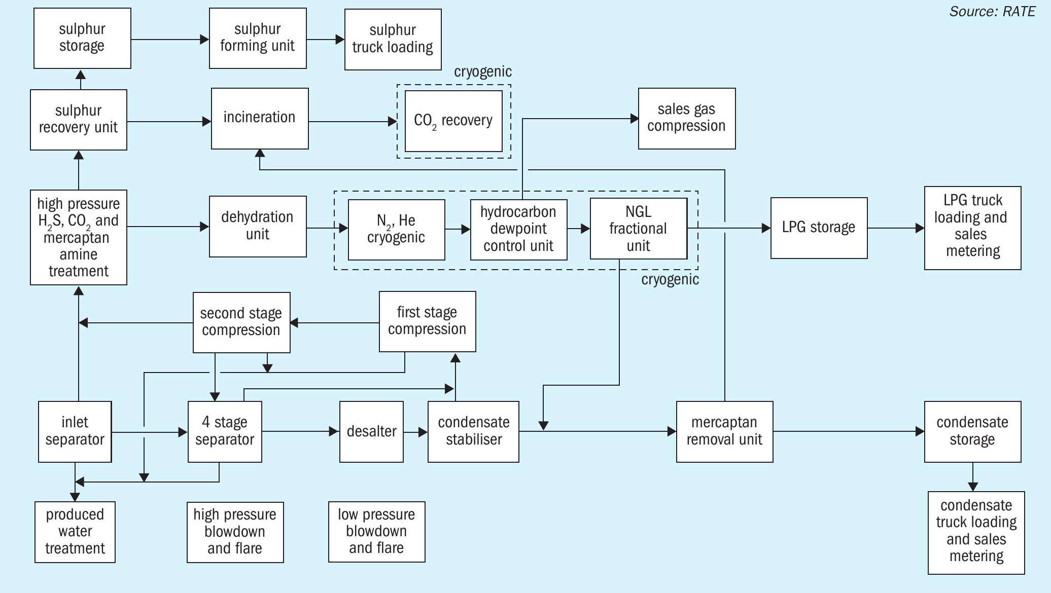
The overall scheme of a sour gas field development is shown in Fig. 1. Cryogenic processes used in the design of a typical gas plant are highlighted.
Liquefied H2S and CO2 reinjection
Acid gas or liquefied acid gas reinjection involves three steps: separation and compression, dehydration and injection. The separation scheme is selected based on the feed composition, capacity, and energy consumption.
Cryogenic bulk removal of H2S and CO2 offers an economic advantage when the separated acid gases from the super sour gas are reinjected.
Acid gas or liquefied acid gas reinjection involves compressing the stream and injecting it into a suitable underground zone, similar to deep well disposal of produced water. Essentially, the sulphur compounds and CO2 are permanently stored in the deep geological formation preventing their release to the atmosphere. Raw natural gas may contain significant impurities, with CO2 , H2S, and N2 being the most important.
“Sour gas” by definition is natural gas that contains H2S. In order to meet sales gas contract specifications, sour gas must be treated for the removal of virtually all of the H2S.
Some gas fields contain very high amounts of H2 S (more than 30 vol-%) or CO2 (up to 70 vol-%) in natural or associated gases. For natural gas with high H2S content, a chemical absorption process with an amine may be used. Typically, the amine absorption method captures most of the CO2 in addition to the H2S. The resulting CO2 + H2S (acid gas) must then be processed to eliminate the H2S. The least cost method to eliminate H2 S is to flare the acid gas stream, burning the H2S to SO2 and releasing the CO2 to the atmosphere, along with the SO2. However, over recent decades, concerns for the environmental effects of sulphur emissions have eliminated flaring as an option for all but the very smallest facilities. Another option is to process the acid gas in a sulphur recovery unit such as a Claus plant, which produces sulphur as a saleable byproduct, but releases the CO2 as before.
Acid gas or liquefied H2S and CO2 stream injection is an important step towards large-scale capture and geological storage of CO2 emissions. It provides an alternative solution to conventional sulphur recovery and tail gas treating units and could serve as a foundation for mitigating CO2 emissions through geological storage
Present energy prices, which are expected to remain substantially higher than before the oil crisis, make the production of even very acidic natural gases attractive. There is therefore an incentive to develop new processes, specifically for this purpose.
This purification can be advantageously carried out by a cryogenic process. However, the thermodynamic behaviour of natural gases containing H2S and CO2 , becomes very complicated in the low temperature zone, mainly because CO2 may crystallise and H2S may cause liquid immiscibility.
Cryogenic distillation processes offer many advantages when the separated acid gases need to be re-injected to limit undesired sulphur production or to minimise greenhouse gas emissions to the atmosphere. They are very selective towards light hydrocarbons, and the separated acid gases (H2S and/or CO2) are recovered in the liquid state under pressure. Producing the acid gases as a high pressure liquid reduces the pumping duty, saving on expensive and energy consuming compression requirements.
RATE offers a variety of schemes to meet project requirements, such as using a membrane in combination with cryogenics liquefaction or the combination of a membrane with selective solvent amine units to remove the bulk of H2S and CO2 and to polish the gas to meet pipeline specifications.
The scheme selected for the acid gas removal section will depend on the acid gas composition and its impurities. If the acid gas contains mercaptans, hybrid solvents are typically used, otherwise chemical solvents are used followed by a polishing unit using adsorbents, mole sieves, or even physical solvents. For energy savings, the combination of a membrane and an amine unit with a selective solvent is usually selected.
In order to use a liquefied acid stream the most economical scheme is to use the combination of a two-stage membrane with the acid gas liquefaction scheme, where the liquefied H2S and CO2 stream is pumped from the surface.
Two-stage membranes are specifically designed to separate H2 S and CO2 from the natural gas. Natural gas is used as the product and H2S and CO2 are sent to the liquefaction process to convert them into the liquid phase. If the sour gas contains heavier hydrocarbons, above C4, some of the heavier hydrocarbons may dissolve in the stream containing H2S and CO2, but in the majority of cases sour gas fields do not have heavy hydrocarbons.
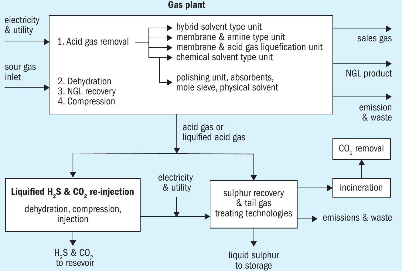
There are two options to treat the recovered acid gas: liquefied acid gas reinjection or conventional sulphur recovery and tail gas treating technologies. The liquefied H2S and CO2 stream would be ready for reinjection after necessary steps like dehydration.
The acid gas removal technology selection is based on the selection for reinjection or to produce sulphur.
The sales gas product is separated and dehydrated and may require hydrocarbon dew point and nitrogen rejection cryogenic processes before it is routed to the pipeline.
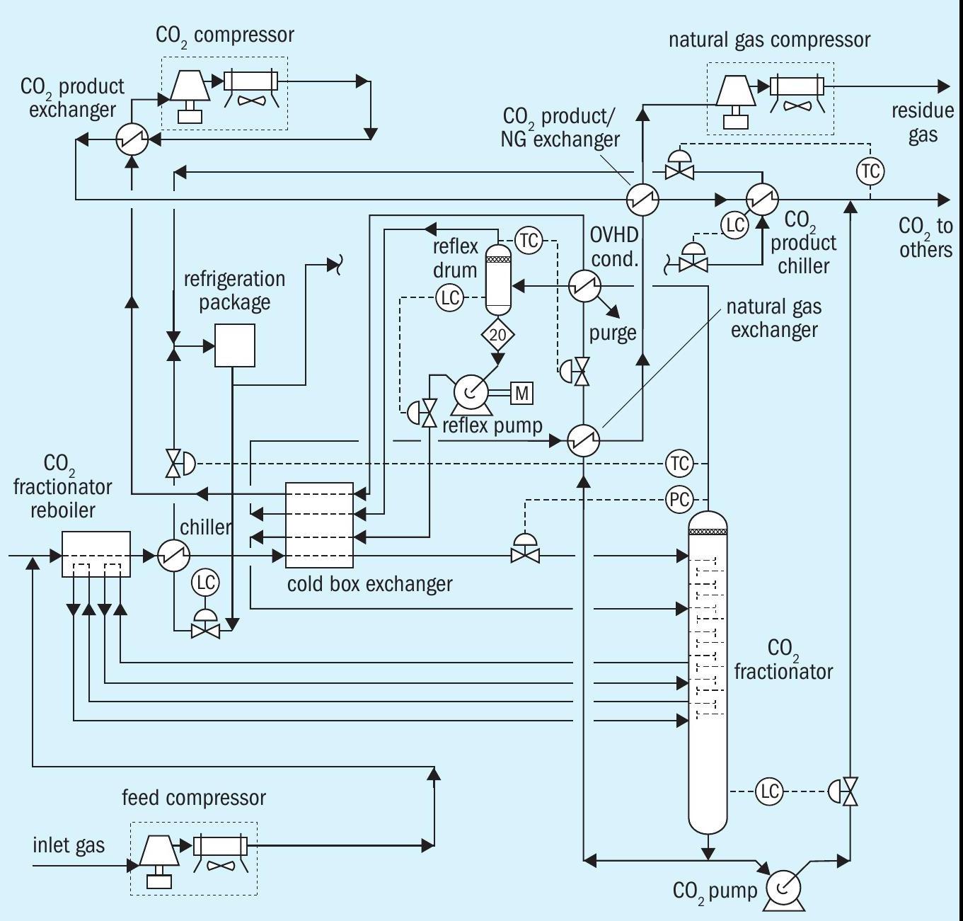
CO2 liquefaction reinjection
CO2 recovery to reduce greenhouse gases from the atmosphere, is one of the hot topics which the oil and gas industry is focusing on and that includes the sulphur plants as well. A number of separation technologies could be employed with post-combustion capture. These include: (a) adsorption; (b) physical absorption; (c) chemical absorption; (d) cryogenics separation, (e) membranes, and (f) RATE technology CO2 liquefaction. On the other hand, pre-combustion technologies include: (a) adsorption; (b) physical absorption; (c) chemical absorption; (d) cryogenics separation, (e) membranes, and (f) RATE combination of a membrane and CO2 liquefaction or selective amine unit.
RATE offers various CO2 removal options depending on the application:
- CO2 liquefaction process with pre and post combustion
- Flue gas decarburisation, including Incineration stack
- CO2 liquefaction process in combination with a membrane, for natural gas
- Selexol process with or without CO2 liquefaction upstream of the SRU
- Selexol with a mole sieve upstream of the SRU
- Rotating packed bed system
- Regenerable and non-regenerable adsorbents
- Adsorbents and membrane standalone or with an amine unit
- Generic amine / formulated solvent, chemical, physical / hybrid solvent
- RATE technology “Deep CO2 removal” bypass part of the acid gas containing high CO2
The recovered CO2 is then stored or reinjected as described above.
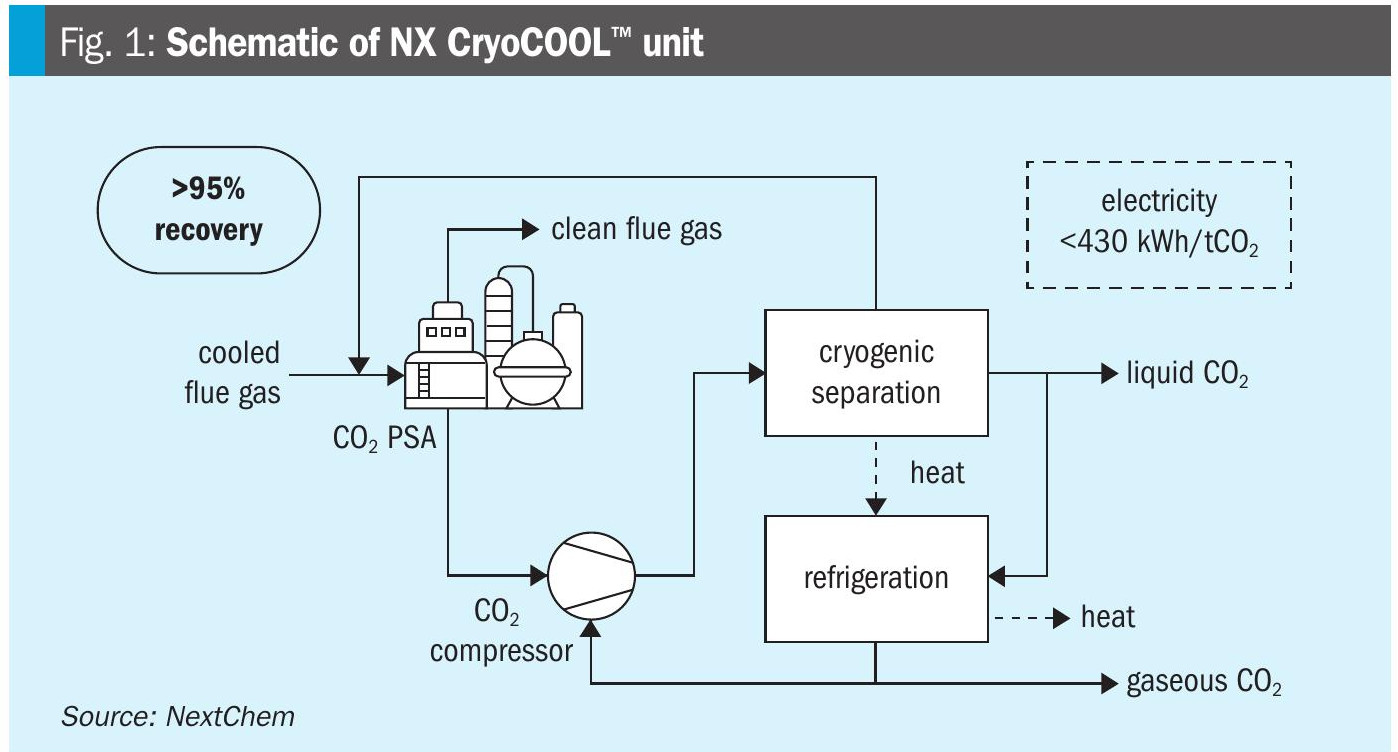
Fig. 3 represents the CO2 liquefaction process.
Hydrocarbon dew point control
The gas from the dehydration unit is treated in the hydrocarbon dew point process. Dew point control plants also produce NGL and LPG, but their main purpose is to eliminate hydrocarbon condensation in pipelines and downstream process units.
The technology selection for this unit depends on the NGL feed composition. The project requires 90% propane recovery. The hydrocarbon dew point process consists of a Joule Thomson (JT) valve with mechanical refrigerator or turbo expander. The option selected is based on 90% propane recovery in the NGL section.
The hydrocarbon dew point is the temperature, at a defined pressure, at which hydrocarbon liquids begin to form. The determination of the hydrocarbon dew point (HCDP) for natural gas has become a critical issue for the natural gas industry because of the rapid expansion of interconnecting pipelines and the rise of non-traditional sources of natural gas. Hydrocarbon liquids in the gas stream can cause hydrate formation, increase compression costs, cause issues with pressure regulator freezing, and lead to damage to end-user equipment such as gas turbines. To protect against this risk, custody transfer agreements are increasingly specifying limits for the HCDP, which, in turn, requires a reliable method of reporting the HCDP at the custody transfer location.
The JT assembly provides hydrocarbon dew point control and increased recovery of natural gas liquids (NGL). The JT plant consists of a gas-to-gas heat exchanger with hot gas bypass, liquid-to-gas heat exchanger, JT valve, cold separator, methanol injection system and control system, all mounted on a single skid. Following gas/liquid separation and gas dehydration, high-pressure gas enters the assembly through the gas/ gas exchanger and chiller for pre-cooling. Methanol is injected to prevent formation of hydrates, and the raw natural gas passes through a JT valve. The resulting pressure drop causes expansion of the gas and a significant temperature reduction due to the Joule-Thompson effect. The cooled gas is routed to the cold separator to remove the condensed NGL. The outlet gas from the cold separator is routed through the gas/ gas exchanger for inlet cooling. The NGL from the cold separator is routed through the inlet NGL/gas exchanger and then to a separate optional pressurised NGL fractionation unit.
The turbo expander assembly provides hydrocarbon dew point control and increased recovery of natural gas liquids (NGL). Refrigerated gas plants recover a large fraction of propane and heavier gases.
JT plants are simpler in design and use high-pressure gas energy to liquefy heavier components by throttling. The Joule-Thomson effect is a physical principle that changes the gas entropy through pressure reduction and produces chilling. Turbo expanders recover a large fraction of ethane and heavier gases.
Recovery rate estimation
Although the amount of hydrocarbon condensate available for recovery may be known, it is important to realise that no process is capable of recovering 100% of this amount. Depending upon the NGL recovery process chosen and the operating parameters set, the total recovery and recovery amount for each component may change dramatically. Additionally, the same equipment processing a stream containing a higher concentration of NGLs will have a higher recovery rate than when processing a leaner stream.
As a rule of thumb, recovery rates for condensate recovery options are roughly:
Joule-Thomson (JT) plant:
- ethane recovery: <20%
- propane recovery: 60%
- butane and heavier recovery: 80%
- Mechanical refrigeration:
- ethane recovery: 40%
- propane recovery: 80%
- butane and heavier: 90%
Cryogenic expansion:
- ethane recovery: 90% minimum
- propane recovery: 95% minimum
- butane and heavier: 99%
JT valves with mechanical refrigeration are selected to achieve near 90% propane only and there is no need for ethane recovery to reduce the capital investment. In addition, due to high recovery of propane, mercaptan treatment is provided on the LPG stream.
NGL recovery and LPG product
In order to understand NGL recovery technologies, it is important to first understand their role in the processing of natural gas. Natural gas may contain ethane, propane, methane and other valuable heavier hydrocarbons. Depending upon market conditions, the recovery of these condensable hydrocarbons, known as NGLs or hydrocarbon condensates may be quite lucrative. Due to the capital and operating expenses typically required to set up and run such a project, careful planning and economic valuation is required.
Natural gas processing using JT with mechanical refrigeration enables the collection of condensates in the absence of high pressure gas sources. The chiller in a mechanical refrigeration unit cools associated gas below -20°F (-29°C) which increases the pressure range over which condensates can condense into liquids. Mechanical refrigeration is flexible in the pre-treatment required, but may leave a significant percentage of condensates unremoved depending on gas composition.
The main advantages are:
- Higher recovery rates than with standalone JT plants;
- No pressure loss is incurred on the gas stream.
– Potentially allows unit to be installed within existing process with minimal difficulty.
- Compression costs are lower than with JT plants
- Much less expensive than cryogenic separation processes.
- May be modular, allowing for rapid relocation.
- A single unit may be able to handle a large range of incoming gas flow rates.
- Condensate recovery may be ‘tuned’ by adjusting the operating pressure.
– Higher pressures will cause increased recovery of propane and ethane.
With high propane recovery and the selection of hydrocarbon dew point the mercaptan removal is only provided on the LPG stream.
Cryogenic nitrogen rejection
When extracted, natural gas is a mixture of gases, with hydrocarbons being the main component. However, raw natural gas also frequently contains the inert gas nitrogen. Nitrogen lowers the heating value of natural gas and increases transport volumes. The challenge lies in reducing this nitrogen content to typically 3 to 4% for pipeline specifications or even 1% for storage as liquefied natural gas (LNG).
Helium is a rare gas and highly valued in the market, making its recovery and liquefaction from natural gas an attractive option even in small amounts. So, if helium is also present in the natural gas stream, nitrogen rejection is typically combined with the recovery of helium. High purity helium is obtained by combining cryogenic and pressure swing adsorption process steps.
There are many gas reservoirs worldwide that contain high levels of ‘naturally’ occurring nitrogen. The nitrogen content in the produced gas of these reservoirs usually remains constant over the producing life of the reservoir. The design of the nitrogen rejection unit (NRU) can focus on an optimum design at a fixed feed composition. Usually, nitrogen is not injected into these reserves to enhance recovery, so the rejected nitrogen has little or no value as a product stream. For this reason, the product nitrogen pressure at the outlet of the process is not important. On the other hand, the hydrocarbon recovery from the vented nitrogen is very important: a typical value for hydrocarbon recovery is 98%.
Cryogenic nitrogen removal is designed based on the nitrogen content. For inlet gas containing less than 20% nitrogen a single distillation column is used. For inlet gas containing more than 20% nitrogen, a double column or 2 column configuration is used. For inlet gas containing above 50% nitrogen, 3 columns are used. The energy consumption and the recovery depends on the inlet gas compositions, and the required recovery.
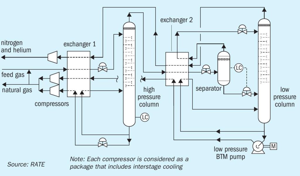
Fig. 4 represents the cryogenic nitrogen rejection process.

Cryogenic helium recovery
The vent gas from cryogenic compressor contains N2 , helium and H2 and is sent to the second stage compressor before entering the helium column via the box exchanger. The tower includes a reboiler and condenser. The H2 is minimised before entering this system. The tower overhead flows to the PSA helium removal unit through the box exchanger. The liquid nitrogen is recovered from the bottom of the column through box changer. The helium is separated and may contain some hydrogen. The PSA vent is separated.
SO2 liquefaction
Mining facilities such as smelters, e.g. in copper mining, produce sulphuric acid from the SO2 streams from furnaces. The amount of SO2 generated in these processes can vary and it may not be possible to control the amount of generated SO2 . In cases where the existing sulphuric acid is operating at maximum capacity and is not capable of receiving more SO2 gases, one option is to use SO2 liquefaction to store the additional SO2 in a dedicated storage tank. This solution prevents the SO2 from being emitted to the atmosphere and does not require an additional sulphuric acid unit.
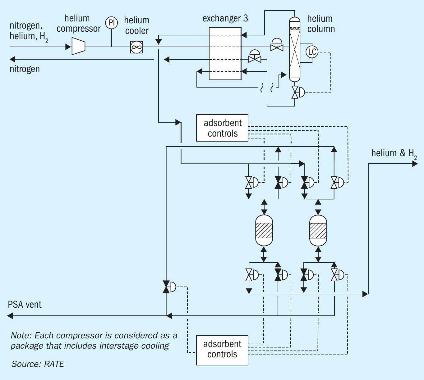
Fig. 5 represents the cryogenic helium recovery for a gas plant.
Sulphur dioxide can be liquefied under moderate pressures at room temperatures; the liquid freezes at −73°C (−99.4°F) and boils at −10°C (14°F) under atmospheric pressure.
Liquid SO2 can be produced from gas containing SO2 concentrations in the range from 1% to 100% using different processes:
- compression and condensation – for high SO2 concentration;
- partial condensation – 7 to 14% SO2 Concentration;
- absorption and acidification – 1 to 2% SO2 concentration;
- sulphur trioxide and sulphur – other application;
- SO2 liquefaction with membrane.
In this article two options are evaluated. The total feed was assumed as 10,000 t/d with 18% SO2 .
SO2 liquefaction only
When the concentration of SO2 in the gas is low (typically 7-14%), it becomes impractical to attempt to fully condense all the SO2 contained in the gas. Extremely high pressures are required in order to use cooling water to condense SO2 from the gas. The alternative to full condensation is partial condensation of the SO2 using refrigeration only. Refrigeration systems can achieve temperatures as low as -55°C (-67°F). Typically, only 50% of the SO2 can be condensed from the gas. The tail gas from the refrigeration process is used to pre-cool the incoming gas prior to being directed to another process for further treatment, e.g. in a sulphuric acid plant.
SO2 liquefaction with membrane technology
In this process, the temperature makes a big difference to the SO2 recovery. At 60°F (16°C) the SO2 recovery is 50% and at 40°F the SO2 recovery is 66%. Without membrane technology the SO2 recovery at 60°F is zero and the SO2 recovery at 40°F (4°C) is 25%.
Membrane technology increases the SO2 recovery significantly. At SO2 concentrations below 30%, SO2 liquefaction only is more expensive with less SO2 recovery, while SO2 liquefaction with membrane technology has a much higher recovery of SO2 and lower electricity consumption.
Conclusions
As discussed above, cryogenic processes have become more essential due to new challenges in the feedstock of sour gas field developments as well as new environmental regulations.
According to RATE’s evaluation, for natural gas with a high content of H2S, the configuration of a membrane followed by acid gas liquefaction will result in the lowest capital and operating costs and will provide much safer operation by using pumps. In addition, it provides a significant reduction of the utility consumptions compared to other acid gas removal options.
Reinjection of H2S and CO2 in the liquid phase provides significant safety features and reduces safety concerns in addition it reduces the capital and the operating costs and reduces mega size compressors station and the electricity consumption. Liquefied H2S and CO2 reinjection provides an alternative to large sulphur plants.
Other cryogenic schemes that are important in CO2 recovery such as CO2 liquefaction are also discussed. Some other cryogenic processes and parameters such as hydrocarbon dew point and nitrogen rejection have an important role to meet the new sales gas specifications.
References