Nitrogen+Syngas 393 Jan-Feb 2025

31 January 2025
Lower cost syngas via nitrogen quenching
Syngas generation units (SGU) comprise one or more hydrocarbons, steam and/or oxidative reformers, a transfer line and a syngas cooling package. Oxidative reformers are based on air, enriched-air or oxygen, and operate according to adiabatic homogeneous syntheses, as partial oxidation reactors (POX) or gasifiers, or according to adiabatic heterogeneous syntheses, as auto-thermal reactors (ATR) or catalytic partial oxidation reactors (CPOX). A combination of steam and oxidative reformers is frequently adopted. The transfer line is a refractory-lined large-size conduit for bringing hot syngas from reforming to the cooling package. The syngas cooling package usually includes a high-pressure water boiler connected to a steam drum; other heat exchangers are often included in the syngas cooling package.
Hot syngas discharged from the reforming operation is at high temperature and pressure; after cooling, the syngas is at operating conditions useful for water-gas shift (WGS) operation. The hot syngas has a high H2 and CO content; it is chemically aggressive towards mild-to-alloy steels at high metal temperatures.
SGU equipment has a complex design and manufacturing process, a long delivery time, and is often based on proprietary knowhow; such equipment is expensive and, in case of problems, is difficult to diagnose, repair or retrofit. Operational problems in syngas transfer lines and cooling packages are annoying and costly, and generally involve some safety concerns.
Possible operational problems in transfer lines and cooling packages
Aging of refractory lining or metal parts is normal under severe thermal-mechanical conditions and when exposed to aggressive gases; yet, when a part of the equipment undergoes faster aging than other parts, the aged part may jeopardise the overall SGU performance and opex, forcing a turndown, shutdown or repair. For instance, local degradation of refractory involves hot spots that, in the worst case, may rapidly evolve to damage pressure parts.
Corrosion or mechanical damage on internal bypass systems, frequently installed in syngas boilers and superheaters, usually leads to difficult outlet syngas temperature control or, in the worst case, to local overheating in the outlet channel or to excessive heat flux in exchanging tubes.
Excessive fines from upstream catalyst or refractory lining can result in excessive fouling on heat exchanging surfaces of the cooling package, eventually leading to poor performance. Such problems are usually difficult to solve; frequent mechanical cleaning may be necessary.
Failure of exchanging tubes in syngas boilers and heat exchangers is rare, typically only occurring after many years of operations. Yet, there are several case studies in the literature describing early failures on exchanging tubes. They may be the result of mis-operation, lack of inspection/maintenance, shifts from boiler water chemistry, operational overloads or poor equipment design/quality.
Finally, although infrequent, high temperature peaks from reforming may temporarily blow the transfer line and syngas boiler leading to local and/or latent damage to the refractory, ferrules, bypass systems and exchanging tubes.
Revamping/retrofitting projects
Revamping projects are aimed at improving ammonia plant production, environmental sustainability and economical balance. Heat and mass balances are tuned, energy consumption is optimised, catalysts are reselected, equipment is fully inspected and retrofitted where necessary. Yet, there are some items of equipment that can represent a critical bottleneck relative to the revamped load making the revamping project challenging from a technical, scheduling and commercial standpoint. The SGU cooling package, specifically the syngas boiler and heat exchangers, typically represents one of the most critical items of equipment in revamping and retrofitting projects.
Existing syngas boilers can usually accept limited revamping conditions from a thermal-hydraulics and thermal-mechanical standpoint. Major limits to running an existing syngas boiler at revamped conditions are peak heat flux at the tube inlets, maximum tube metal temperature, steam disengagement and stresses in the tubesheet and tube-to-tubesheet joints. Moreover, aged syngas boilers may seriously suffer from revamped conditions. Therefore, revamping projects often involve replacing the existing syngas boiler or exchangers.
NITROQUENCH technology
NITROQUENCH is a new process method for ammonia syngas generation units. Specifically, it is conceived for ammonia SGUs based on adiabatic oxidative reforming by enriched air or oxygen, where an air separation unit (ASU) is installed. Availability of cold nitrogen (N2 ) is essential, regardless of the source (ASU or imported nitrogen). NITROQUENCH can be adopted for new and revamping projects; it can also be implemented in existing ammonia SGUs as an add-on.
The new method comprises direct cooling of the hot syngas discharged from the reforming operation by mixing with cold N2; the direct cooling is accompanied by the indirect cooling of the conventional syngas boiler/exchanger. The cold N2 is liquid or gaseous or supercritical, preferably in cryogenic conditions, and is injected into the hot syngas by means of an injector mounted on the SGU equipment. N2 is an inert species and takes part in the subsequent ammonia synthesis: its injection is therefore harmless. Fig. 1 depicts a typical ammonia SGU equipped with an ASU and implemented with NITROQUENCH. The SGU comprises an oxygen-based ATR, a transfer line, a syngas boiler and steam superheater (SSH) connected to a steam drum; a water gas shift (WGS) reactor is installed downstream of the SGU. The hot syngas from the ATR is first mixed with a cold stream of N2 along the transfer line, then cooled down in the boiler and superheater.
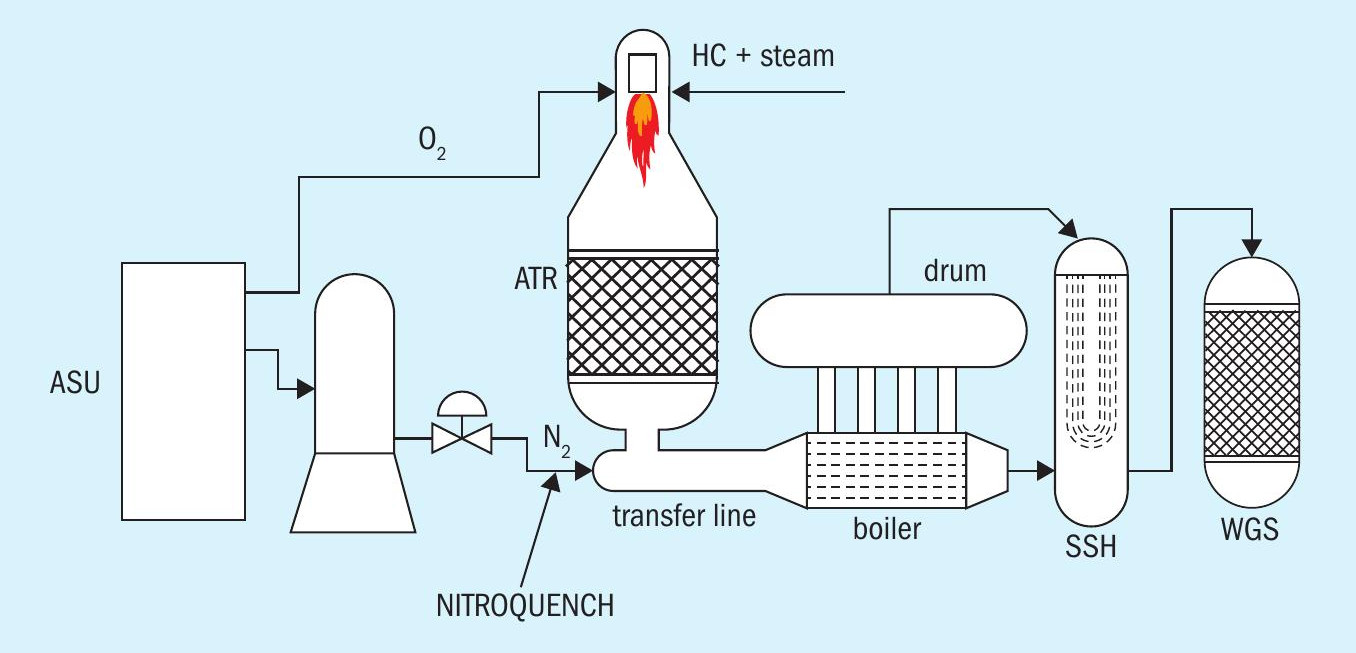
Fig. 2 shows possible conceptual schemes of NITROQUENCH. The SGU includes the reforming, the transfer line and the cooling package. The reforming can be realised by any combination of reforming reactors (A = adiabatic pre-reforming, B = radiative steam reforming, C = convective steam reforming, D = adiabatic ATR/CPOX, E = adiabatic POX/ gasifier); NITROQUENCH technology is chiefly conceived for ATR, POX and gasifiers working with O2. The cooling package includes two heat exchangers installed in series. The cold N2 is conveyed from cryostorage to the SGU by an injection line and is injected into the hot syngas either upstream of the first heat exchanger (N-1) and/or in between the two heat exchangers (N-2) and/or downstream of the second exchanger (N-3). Operating temperatures shown in Fig. 2 are indicative only: the hot syngas is cooled down after mixing with cryogenic N2 .

NITROQUENCH is an intuitive and practical method. Use of cryogenic N2, already available at site, to cool the hot syngas could also be regarded as smart use of low enthalpy. Depending on the N2 physical state, temperature and flowrate, and depending on the process plant design and/or on the operational problems, the syngas temperature can be reasonably lowered by 10-100°C; the direct cooling is fast and with negligible syngas pressure drop. When applied upstream of the cooling package, major operational advantages of NITROQUENCH include:
- refractory hot face is at a lower temperature: possible hot spots or aging phenomena are mitigated;
- syngas temperature at the boiler/ exchanger inlet is reduced: heat flux, thermal and mechanical stresses are lessened;
- heat load on boiler/exchanger is reduced: heat transfer performance and hydraulics are eased;
- possible temperature peaks from reforming are prevented and smoothed;
- additional process control of the SGU is possible by regulating temperature/ flowrate of cold N2 .
When NITROQUENCH is applied downstream of the cooling package (and upstream of the WGS), the further cooling of syngas provides a major operational advantage when the boiler/exchanger has poor performance or is damaged: NITROQUENCH may restore the target syngas temperature at the WGS reactor inlet.
The abovementioned advantages lead to an extended lifespan of existing or aged equipment, mitigation of operational problems, restored performance, and equipment protection. For revamping or retrofitting projects, NITROQUENCH may enable the existing transfer line and syngas boiler/ exchanger to be kept, despite the revamped load or operational problems. In case of new projects, NITROQUENCH may decrease syngas boiler/exchanger dimensions and reduce mechanical design conditions.
Finally, it is important that the NITROQUENCH flowrate is preferably balanced with other possible N2 injections (e.g., N2 washing) to provide entry in the ammonia synthesis with a proper H2:N2 ratio. On the contrary, as when air is used for partial oxidation, excess N2 must be removed (for instance by N2 washing).
Illustrative example 1
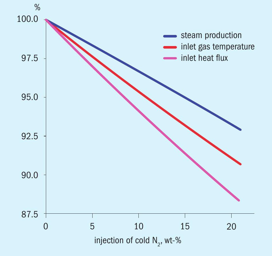
An existing partial oxidation reactor operated with O2 discharges a syngas for subsequent ammonia synthesis with a mass flowrate, temperature and pressure of 192,000 kg/h, 1,000°C and 3 MPa(a) respectively; the relevant molar composition is H2 = 45.9%, H2O = 29.4%, CO = 16.2%, CO2 = 6.8%, CH4 = 0.8%, N2 = 0.8%, Ar = 0.1%. The syngas is cooled in a shell-and-tube boiler by means of high-pressure water boiling at 320°C circulating on the shell side; the design heat flux at the boiler inlet is 360 kW/m2. Due to general signs of corrosion and local damage, there are concerns about the reliability and lifespan of the transfer line and boiler. Cryogenic gaseous N2 is available at the plant at -140°C and 3 MPa(a), therefore NITROQUENCH can be implemented upstream of the boiler. Fig. 3 shows the trend of major thermal parameters against the N2 injection flowrate. For instance, by injecting 7.5 wt-%(14,400 kg/h) of cold N2 upstream of the boiler, the syngas temperature and heat flux at the boiler inlet are reduced by 3.4% (966°C) and 4.3% (345 kW/m2 ) respectively. Accordingly, the thermal-mechanical conditions in the transfer line and at the boiler inlet are significantly lessened; equipment reliability and lifespan are improved without reducing the plant production. The overall steam production in the boiler is reduced by 2.6% only.
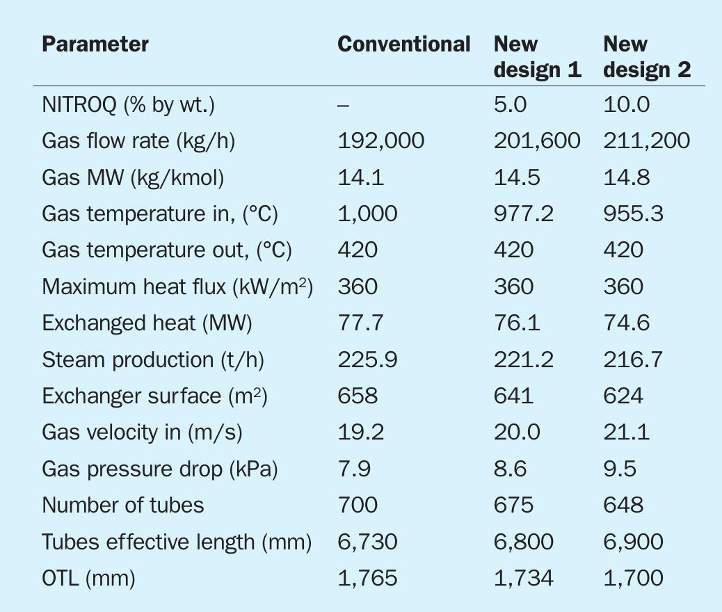
Illustrative example 2
The syngas boiler of example 1 is planned to be replaced. Table 1 compares the boiler conventional design to the new design by implementing NITROQUENCH upstream of the boiler as in example 1. The comparison is based on identical exchanging tube, tube pitch, design heat flux, outlet syngas temperature and fouling coefficients. The new boiler based on NITROQUENCH can have a reduced tube number and diameter. For NITROQUENCH at 10 wt-%: (i) gas velocity at the tube inlet is increased by 10% (21.1 m/s) and this has a better cleaning effect, (ii) the inlet syngas temperature is lowered by 4.5% (955.3°C), which leads to lower thermal-mechanical stresses in the inlet parts (refractory, ferrules, tubesheet), (iii) the steam production is reduced by 4% (216,7 t/h), which may be considered an improvement for thermal-hydraulics, or an energy optimisation or part of heat balance tuning. In addition, if NITROQUENCH is implemented downstream of the boiler, a downstream injection of 5 wt-% of cold N2 would lead to a tube length reduction of approximately 6%.
Conclusions
NITROQUENCH is a process technology aimed at optimising the design and mitigating typical operational problems of the ammonia SGU, chiefly based on oxygen partial oxidation. The availability of cryogenic N2 is essential. Beyond its potential advantages, NITROQUENCH can be rapidy implemented and is cost-effective: generally, installation material comprises a 2” to 6” stainless steel line, a flow meter and regulating valve, and an injector. The technology could also be implemented in other process plants, such as H2, HNO3, HCN or CH2O plants: the quenching nitrogen can be separated from the final product by any physical method, such as pressure swing adsorption, a selective membrane, or by condensation. NITROQUENCH is available on demand for process licensors, engineering companies and final users.