Sulphur 416 Jan-Feb 2025

31 January 2025
Optimising European SRU incinerators
SRU INCINERATORS
Optimising European SRU incinerators
The 2030 greenhouse gas emission reduction goals in the European Union are driving oil and gas producers to reduce CO2 emissions wherever possible. This extends to even the incinerator attached to a sulphur recovery unit (SRU). In this article Sulphur Experts review the role of the incinerator, how the three most common European TGUs each affect the demand on the incinerator itself, and the potential reduction in CO2 emissions for a generic facility of each type.
Leah Goettler, Peter Seville, Jan Kiebert (SGS Sulphur Experts)
The sulphur recovery unit (SRU) often gets left out of money-making conversations. Its entire purpose is to minimise SO2 emissions, which is a noble cause, but rarely a profitable one. Optimisations in this part of the process have historically been focused on avoiding fines for emissions violations, improving reliability, or adjusting throughput in response to market or feedstock changes.
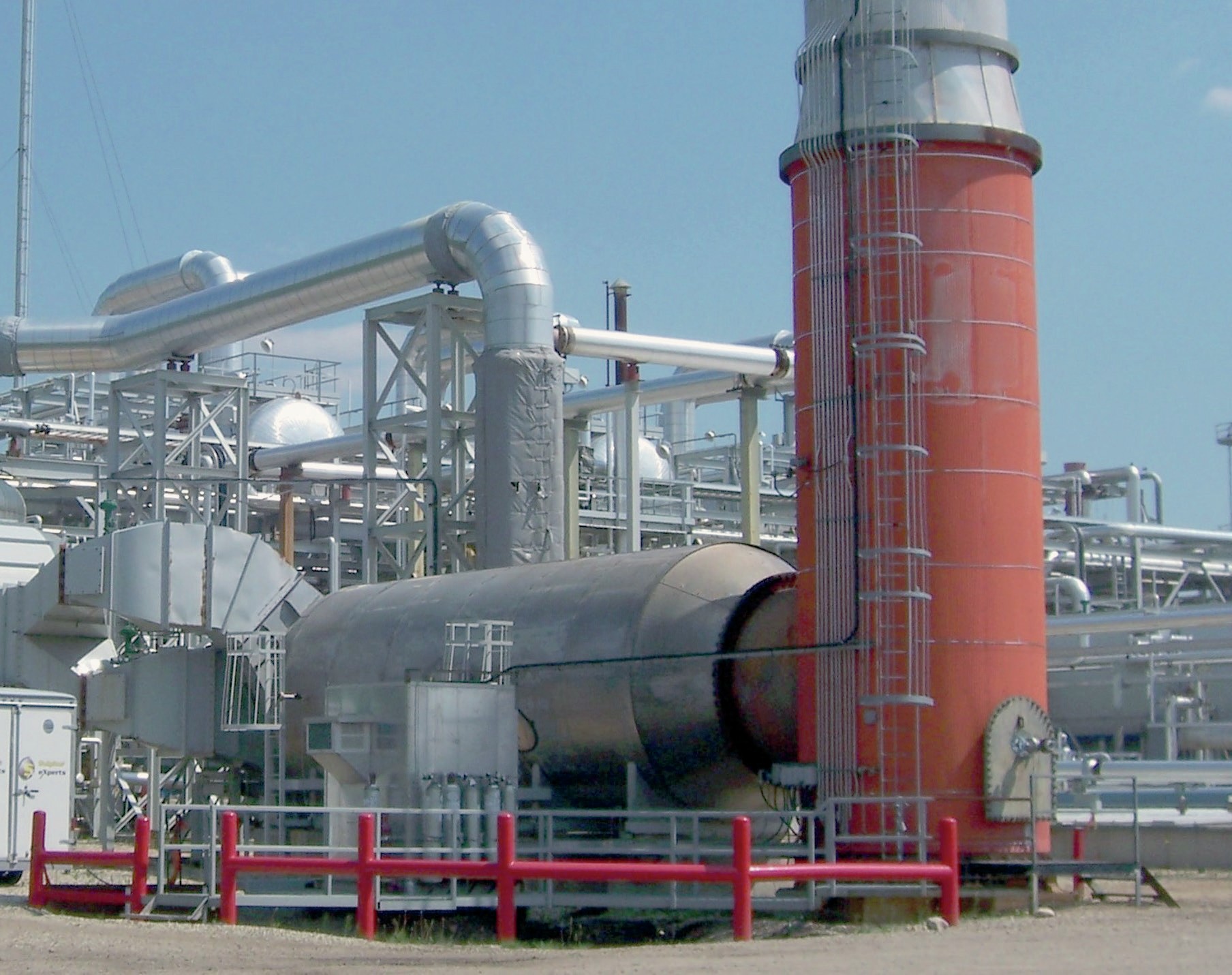
At the very end of the SRU lies the humble incinerator. A simple design for a simple purpose: to take the leftover sulphur-containing compounds and burn them all to SO2. While often forgotten or ignored, it is still possible to optimise this part of the process and Sulphur Experts have encouraged operators around the world to do so for decades. There are several benefits, including using less fuel and therefore reducing operating costs. Some refiners in Europe burn city or natural gas in the incinerator and the cost of natural gas has increased over the last few years, from approximately €15 per MWh between 2016 and 2020 to now approximately €35 per MWh. But many refineries can use the fuel gas produced on-site in the incinerator and so this change may not affect all operators’ wallets. Nonetheless, reducing fuel use can sometimes eliminate unnecessary SO2 emissions from H2S or mercaptans that may be left in the refinery fuel gas.
Optimisation also means reduced NOx and SO3 emissions, which means less smog formation and “acid rain”, associated with airborne sulphur compounds. Very importantly, it also means emitting less CO2. And while this has been an excellent marketing slogan for several decades, there are now very real (and financial) reasons to care about CO2 emissions reductions. The European Commission released The European Green Deal back in 2019. The goal is a climate-neutral Europe by 2050, with an original interim 2030 target of reducing CO2 emissions by 55% compared to 2005 levels; this has recently been updated to a 62% reduction target for 2030. In order to achieve this, each tonne of CO2 or CO2-equivalent must be accounted for with an “allowance”. Certain industries receive a number of free allowances each year, but that number of allowances will decrease over time to encourage companies to maintain or increase their efforts. If more allowances are needed, they can be bought on the European Energy Exchange, and likewise, unused allowances can be sold there. SRU incinerators could offer low-hanging fruit to help operators make the most of this new CO2 commodity trading.
Unlike their North American counterparts, European SRU incinerators have a greater variety of incoming contaminants to deal with due to the greater number of non-amine-based tail gas units (TGUs). Add on additional regulations for various airborne pollutants, and a larger number of catalytic incinerators in service, and optimisation becomes a more complex process.
The typical European SRU incinerator
Before optimisation can start, it is important to fully understand what the typical European incinerator system looks like. This includes the feed gases, the technology used to oxidise the contaminants, and its typical operating conditions.
Incinerator inlet
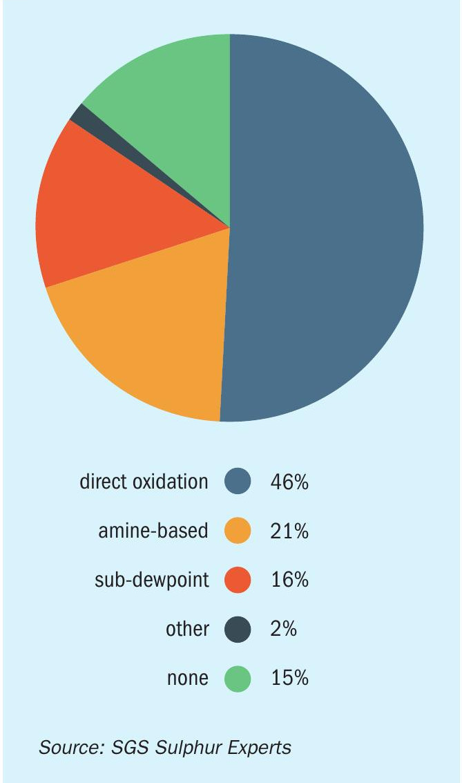
The type of TGU attached to the SRU directly affects the composition of the incinerator inlet gas. Based on the Sulphur Experts test database from 2015 to 2023 (see Fig. 1), there are three main types of TGU operating in the European region: direct oxidation, amine-based, and sub-dewpoint. It was also commonly found that some refineries had no TGU of any type, usually in countries with less stringent emissions limits, or from earlier tests. There are also a small number of facilities that have comparatively rare systems (for example, LO-CAT®or Sulferox) – these are outliers and beyond the scope of this paper.
As the main goal of the incinerator is to ensure complete combustion of the contaminants in the SRU tail gas, it will not affect chemical compounds such as water, carbon dioxide, sulphur dioxide, and nitrogen. Table 1 shows the typical concentrations of combustible inlet contaminants depending on the TGU type. These values are generalised from Sulphur Experts testing data from 2021 to 2023, and are based on air-only operation in the modified-Claus unit reaction furnace. Oxygen enrichment of the combustion air would concentrate these species since there is much less nitrogen in the process.
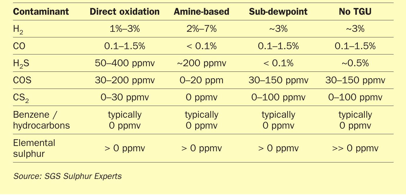
The next most prevalent type is an amine-based system, wherein all non-H2S sulphur components are converted to H2S with a hydrogenation catalyst. Most of the CO is also converted to H2 via the gas-water shift reaction. The process gas is then cooled, sent through a quench tower to remove excess process water, and finally sent through a low-pressure amine absorber. The overhead gas is sent to the incinerator. A regenerator strips out the H2S from the amine and the H2S-rich gas is recycled to the front of the SRU. Given the various reactions that occur over the hydrogenation bed and the separation of the H2S in the absorber, the gas sent to the incinerator is much cleaner than the original Claus tail gas.
The third most popular TGU type is sub-dewpoint. There are various technologies and configurations on the market, but they are all consistent in that they use a semi-batch processing method to allow the Claus reaction to proceed further by operating below the dewpoint of elemental sulphur. At least two beds are needed such that one is tied in to the process while the other is regenerated by having the liquid sulphur boiled off. Since this TGU type is purely an extension of the modified Claus reaction, the tail gas sent to the incinerator will look exactly like a Claus tail gas, just with less H2S and SO2.
Hydrogen (H2 ) and CO are formed in the Claus section reaction furnace due to the combustion of hydrocarbons in the reducing atmosphere. The exact concentration depends on the proportional volume of hydrocarbons in the SRU feed gases. Hotter temperatures encourage more CO formation. The amount of H2 and CO passes through the Claus, direct-oxidation, and sub-dewpoint units unchanged, therefore, the composition of the gas leaving these processes is relatively similar. There is some variation when dealing with direct oxidation TGUs, as variations of this technology, such as the upstream process EUROCLAUS ®, involve a hydrogenation and hydrolysis step that will affect the tail gas H2 , CO, COS, and CS2 concentrations. Amine-based TGU systems depend on having an excess of hydrogen to reach thermodynamic equilibrium in the hydrogenation reactor. Therefore, the hydrogen content of the Claus section tail gas is increased either in the form of a supplemental hydrogen stream (of varying purity), or via a direct-fired reheater operated sub-stoichiometrically to produce additional H2 and CO. The CO participates in the gas-water shift reaction to form additional hydrogen within the reactor vessel. Healthy catalyst leaves some, but relatively little, residual CO in the reactor tail gas.
The H2S concentration in the tail gas will vary based on the number of Claus stages and the activity of each reactor. Direct oxidation reactors with good activity can achieve lower tail gas H2S concentrations than even some amine-based TGUs. COS and CS2 are formed in the reaction furnace due to the presence of CO2 and hydrocarbons in the feed gases, and their concentrations are also related to reaction furnace temperature. Hotter temperatures favour COS formation, while relatively cooler temperatures favour CS2 formation. Roughly 95% of these species are typically hydrolysed in the first Claus reactor, which is intentionally operated hot (300-320°C) for this purpose. Subsequent Claus reactors and sub-dewpoint TGUs have no effect on COS and CS2 . Some direct oxidation technologies, when the catalyst has aged, can form some COS. As stated previously, COS and CS2 are hydrolysed over the amine-based TGUs hydrogenation catalyst bed. Residuals are very low, with COS being less than 20 ppmv typically and CS2 being present only in severely deactivated beds.
Hydrocarbons, including straight-chain and the infamous BTEX (benzene, toluene, ethylbenzene, and xylene), are rarely found in the tail gases regardless of the type of TGU system. If they are present, it is typically due to: an upstream direct-fired reheater operated with poor burn stoichiometry or burner damage; a contaminated supplemental hydrogen stream; or hydrocarbons caught in the amine loop from previous contamination.
Finally, elemental sulphur also needs to be considered as a process contaminant to the incinerator. Even if entrained liquid sulphur droplets are not present, most process tail gases will always have some residual sulphur vapour, which is a function of the H2S concentration in the total feed and the outlet temperature of the system’s final condenser. The tail gas from sub-dewpoint systems will naturally contain much less sulphur vapour than Claus and direct oxidation processes. Only the amine-based TGUs are elemental sulphur free. Unfortunately, most incinerators must also process a separate sulphur pit sweep or degassing stream which always introduces some elemental sulphur (and more H2S) to the incinerator regardless of the type of TGU.
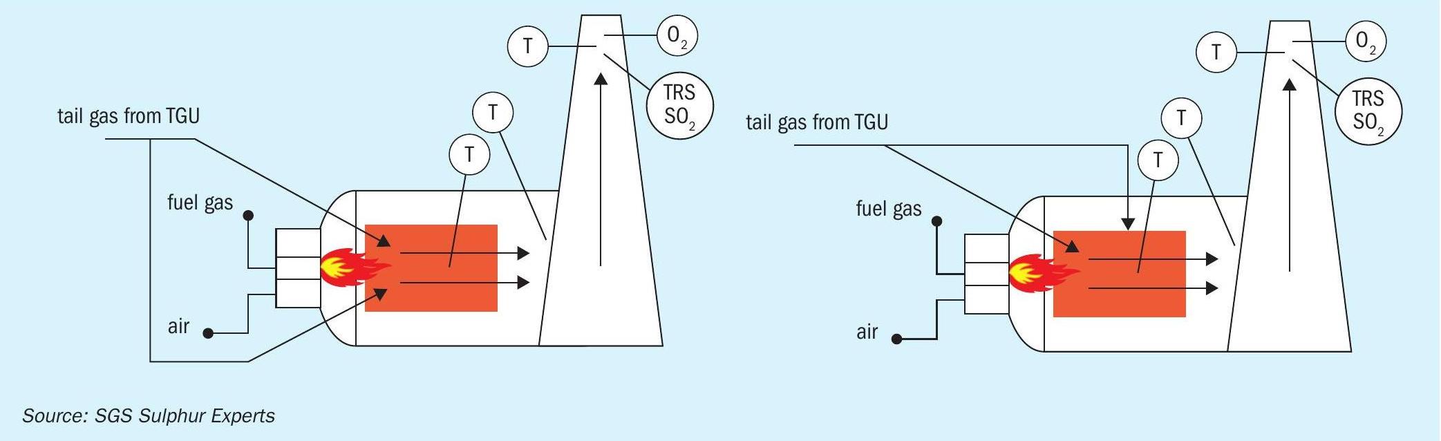
Types of incinerators
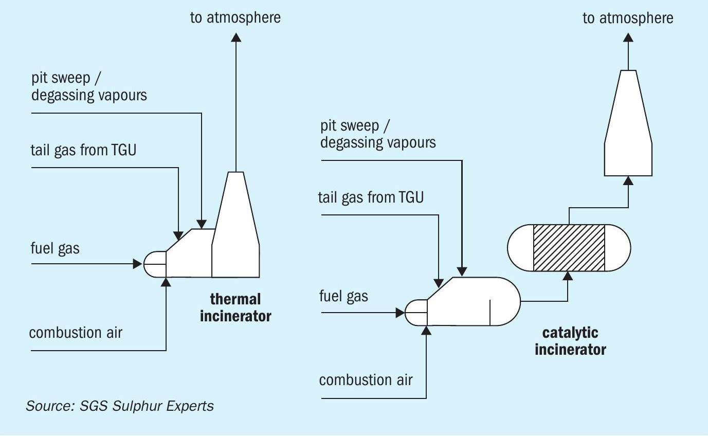
There are two main types of incinerator: thermal, and catalytic (Fig. 2). Thermal oxidisers use one or more burners within a refractory-lined chamber, and rely simply on adequate time, temperature, and mixing to achieve adequate combustion of the inlet contaminants. Catalytic incinerators also use a burner, but then pass the gas through a catalyst bed which increases the oxidation reaction rate. This allows those reactions to occur at colder temperatures than needed in thermal incinerators. Thermal incinerators are typically operated at temperatures between 650°C and 1,100°C. In a catalytic incinerator, the inlet temperature to the bed will be between 150°C to 475°C. Based on Sulphur Experts’ database, roughly 28% of European SRU incinerators are catalytic while the remainder are thermal oxidisers. Europe has many more catalytic incinerators in service than North America.
Catalytic incinerators are generally more efficient than thermal devices in terms of plot space and operating cost. In SRUs, they are only truly effective in destroying H2S. The standard catalyst used in catalytic incinerators is, unfortunately, very poor at burning COS, CS2, H2, or CO. There are specialised catalyst blends that would be able to burn these species, but they are designed for different units and have yet to be implemented in SRU systems. Catalytic incinerators may be a good choice for amine-based processes since they have less of these contaminants. In addition, most configurations require that the process feed gas have a low heating value (to control the temperature increase across the catalyst) and a low particulate content (to avoid fouling the catalyst).
Thermal incinerator operation
There are two major operating factors that affect combustion efficiency: combustion temperature and oxygen concentration. Residence time and turbulence/mixing are more reliant on good design and construction. Therefore it is assumed that the incinerator burners have sufficient throughput to ensure the correct gas velocity through the nozzles and good mixing.
Fig. 3 shows a compilation of European thermal incinerator combustion chamber temperatures as recorded by Sulphur Experts since 2015. Only tests which included analytical measurements of the stack gas are included. The data have been filtered to remove duplicate testing of the same incinerator, although several refineries employ two or more incinerators to process the SRU tail gas, in which case, all incinerators are listed. Duplicate testing of incinerators over several years has also been removed, and the most recent test always presented. Generally speaking, a facility will commit to one type of incinerator if multiple are required; likewise, an operator in a certain region may generally prefer one type of incinerator over the other. The same mentality is applied to temperature and excess oxygen targets. This is why several tests have comparably similar combustion temperatures. Data points are coloured according to the TGU system upstream. The most common countries for the data point regions are also listed for interest. As can be seen, the operating temperatures vary from 600°C all the way to almost 1,000°C. The average reported combustion temperatures for different groups of TGUs are:
- direct oxidation = 734°C
- amine based = 775°C
- no TGTU = 743°C
- sub-dewpoint = 843°C
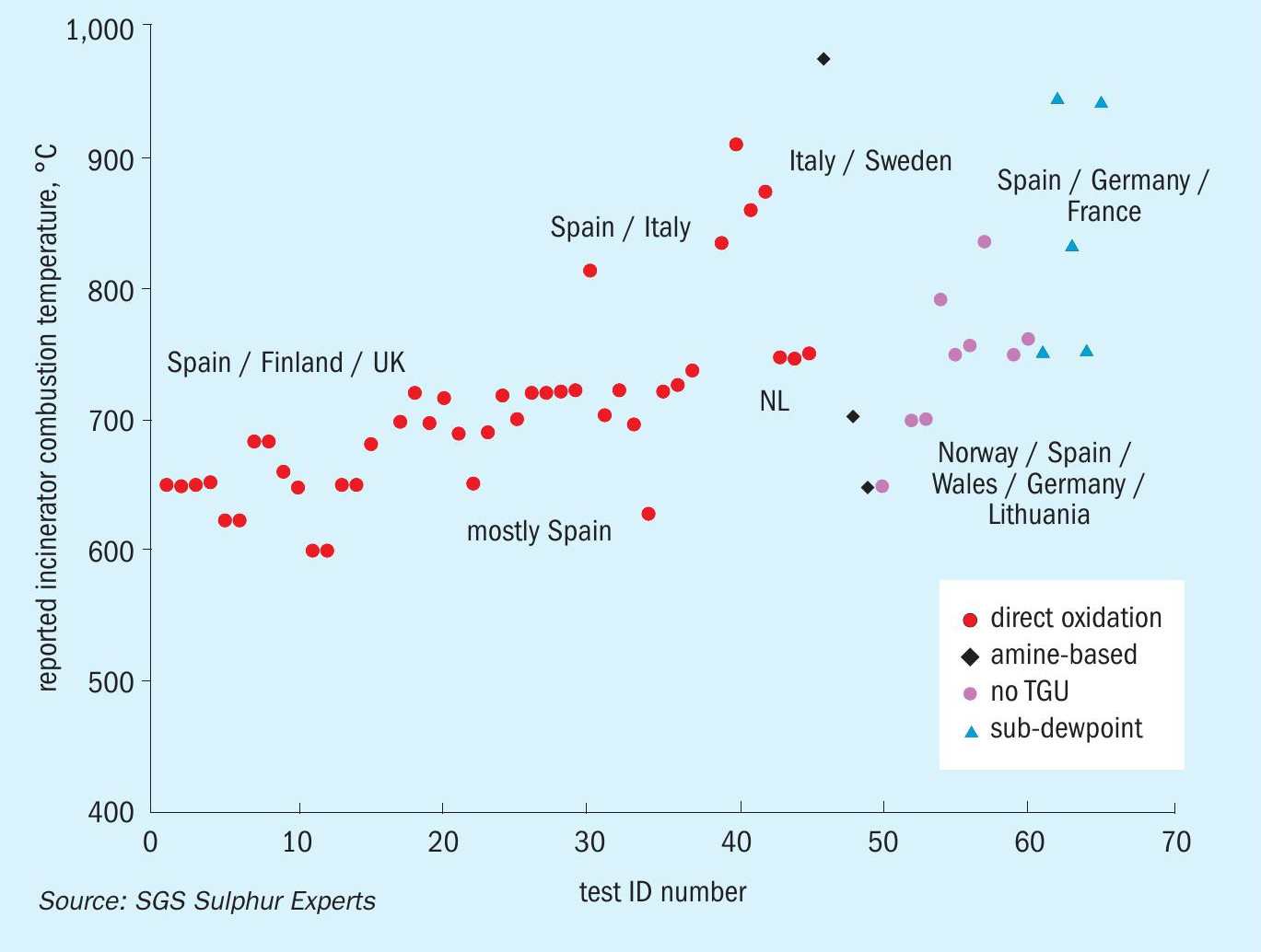
The European averages are all significantly hotter than their USA counterparts, which run on average at about 700°C. Sulphur Experts have no universal target for combustion temperature, as the goal is simply complete (or at least adequate) combustion. Operators target whichever temperature allows them to comply with their local emissions limits. The European Union has limits and targets for airborne contaminants in the categories of:
- SO2 (and associated sulphur oxides and reduced sulphur compounds such as H2S and mercaptans);
- fine particulate matter (PM2.5), meaning particles with aerodynamic diameters less than or equal to 2.5 µm;
- nitrous oxides (NOx);
- ammonia (NH3); and, l non-methane volatile organic compounds (NMVOCs), meaning all non-methane organic compounds capable of forming photochemical oxidants via reaction with NOx in sunlight.
The Directive 2008/50/EC of the European Parliament consolidated as of 2015 details the emission thresholds for other additional contaminants including lead, benzene, and carbon monoxide, among others. Each country, or even region, may of course impose its own stricter limit. Several of these regulated compounds do not exist in SRUs, so only the relevant ones will be discussed. Table 2 lists the main contaminants found in the SRU tail gas along with their auto-ignition temperatures in air. While these should not be used as exact operating temperature targets, the table shows which contaminants are the most difficult to combust and the minimum temperatures required to do so.
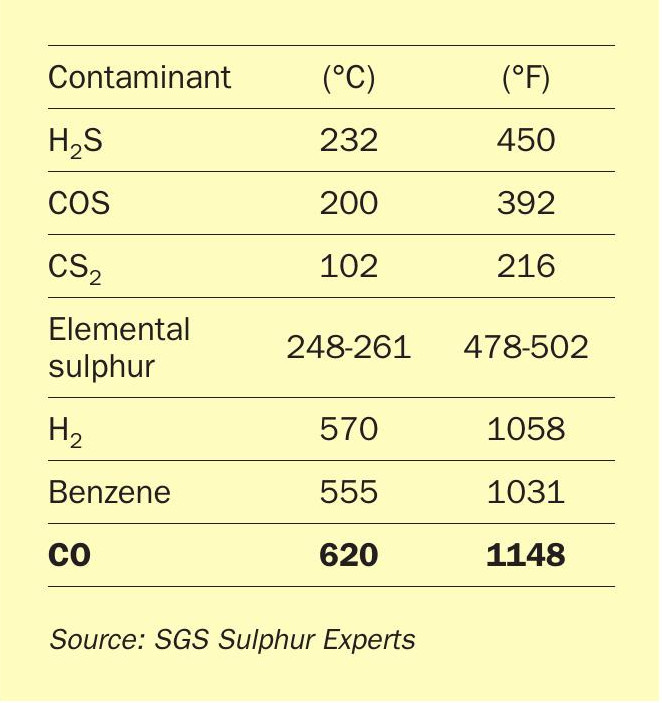
NOx and SO3 are mainly formed inside the incinerator, especially when run too hot and with too much air. As stated previously, benzene would generally only appear in the feed to the incinerator if it was in the fuel gas, but typically this is not an issue.
Regulations surrounding CO emissions are due to its role as an ozone precursor, similar to nitrogen oxides. CO contributes to the formation of tropospheric (ground level) ozone which can negatively affect human health and also indirectly contributes to climate change. It’s important to note that CO limits were typically written for fired equipment in power plants, boilers, heaters, and catalytic cracking. Their aim was to avoid CO formation in the burner itself, not necessarily to fully combust incoming CO. Although the individual country regulations for CO differ, many of them are based on the 2015 “Best Available Techniques (BAT) Reference Document for the Refining of Mineral Oil and Gas Industrial Emissions”. This documents states the following:
- CO emissions from partial combustion processes range from 20 to 42 mg/ Nm3 at 3% O2;
- the BAT-associated emissions levels for CO to air from a combustion unit are less than or equal to a monthly average of 100 mg/Nm3 ;
- “In the case of conventional firings, a CO concentration below 50 mg/ Nm3 [43 ppmv] is achievable at temperatures above 800°C, at sufficient air delivery and sufficient retention times”.
Generally speaking, most European countries adhere to the CO maximum emission limit of 100 mg/Nm3 at 3% O2 , if not less. Since CO is the hottest temperature hurdle for good combustion, this may explain why European incinerators run hot compared to many of their North American counterparts, where most locations do not have as strict limits, when they have them at all.
Another complicating factor is that European refineries often have a waste heat recovery system on the waste gas. This produces steam which is useful elsewhere in the unit or refinery and encourages operators to run the incinerator at temperatures hotter than necessary. It also limits the range of temperatures that can be targeted. For comparison, North American incinerators generally do not have a waste heat recovery system. As this limitation is facility-dependent, it will not be discussed in this article. However, consideration should always be given to downstream equipment and utility requirements when optimising the incinerator.
Excess oxygen
Excess oxygen (O2) is a metric used to ensure the right amount of air is provided to completely oxidise the species of interest. Many facilities put an oxygen analyser on the outlet of the incinerator to monitor this parameter. This may be a passive analyser or it may be connected to the combustion air control scheme. From an efficiency perspective the ideal excess oxygen target is between 2 and 5 mol-%. Operation with less than 2% may not completely burn the target species, especially if the fuel gas composition is unstable, if there is a shift in load to the incinerator such as a change from low-to high-sulphur crude, or during the moment of instability such as when the TGU is bypassed. Operating with more than 5% excess O2 also does not significantly improve combustion efficiency. Rather, it has a number of disadvantages that include increased risk of sulphur trioxide (SO3) formation and the associated corrosion and plume visibility and an increased risk of nitrogen oxide (NOx) formation. Furthermore, adding more air than necessary increases the amount of mass that needs to be heated to the target temperature – this wastes fuel, which may have cost implications, depending on its source and value.
The measured excess oxygen concentrations for the same tests as shown in Fig. 3 are provided in Fig. 4. The same filtering parameters have been applied as were used for the combustion temperature data.
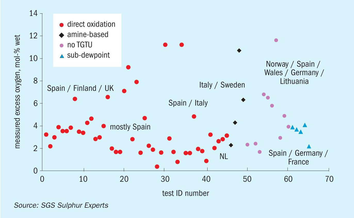
As can be seen, most of the tested incinerators use a target excess oxygen range of 2 to 5%. None of the tested subdewpoint TGUs had O2 values more than 5%, for example. Of those which operated with more than 5% excess O2, the averages are as follows:
- direct oxidation = 8.5%
- no TGTU = 7.7%
- amine-based = 8.5%
- sub-dewpoint = 4.0%
Optimised European thermal incinerator
To standardise the optimisation process, the Aspentech HYSYS ® Sulsim package was used to simulate a theoretical 100 t/d 3-stage Claus unit, operating at a 2-to-1 H2S/SO2 tail gas ratio with a final condenser outlet temperature of 135°C. This section was then simulated after attaching the four different TGU systems using good KPIs and with incinerators using the average temperature and excess oxygen concentrations found in the historical data.
Temperature optimisation
As mentioned earlier, European incinerators typically run hot due to their CO emissions regulations. But as CO is regulated mainly due to concerns of human health, and not because it is a greenhouse gas, it is not possible to optimise temperature on the basis of CO2 equivalence.
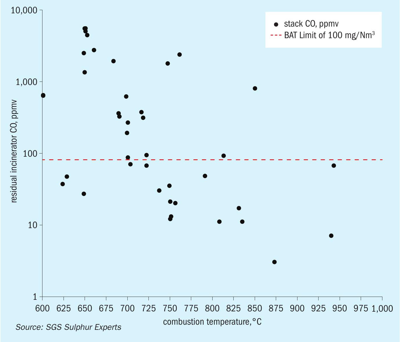
Many facilities operate their incinerators hotter than 800°C to adequately combust CO. But Sulphur Experts’ testing data from 48 historical European tests on thermal incinerators shows that the 100 mg/Nm3 (about 80 ppmv) BAT limit can be achieved at temperatures as cool as 625°C (Fig. 5). A more consistent and conservative target appears to be around 725°C. This is anywhere from 9C° to 118C° less than the average reported operating temperature, depending on TGU type. To operate colder successfully therefore requires either less inlet CO or better mixing efficiency.
The amount of CO coming into the incinerator is mainly a function of CO2 and hydrocarbon content in the feed gases to the SRU and the operating temperature of the Claus reaction furnace. These parameters are generally out of the control of the operator. The feed gas composition is dependent on upstream operations and crude type. The reaction furnace temperature is set to ensure thorough destruction of contaminants (BTEX and NH3 ) ahead of the Claus reactors. All TGU systems have similar tail gas CO concentrations, except for the amine-based one which takes advantage of the gas-water shift reaction in the hydrogenation bed to remove nearly all of the CO from the tail gas stream by changing it into H2.
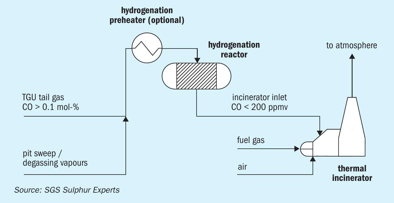
To take advantage of this reaction in non-amine-based TGU systems, a hydrogenation reactor could be placed just upstream of the incinerator (Fig. 6). This would convert a significant portion of the CO to hydrogen and most of the SO2 into a combustible H2S when it enters the incinerator. Data show that a healthy hydrogenation catalyst will reduce the CO concentration from approximately 1.0 mol-% down to 200 ppmv or less. In the incinerator, this means significantly less natural gas is required to meet the BAT CO emissions limit. Unlike with a traditional amine-based TGU, the other components such as the cooler, quench tower, and amine system are not required in this design. The normal concerns of SO2 breakthrough in a standard amine TGU would also not be relevant. However, this option requires significant capital investment, some additional operating expense, and also requires more plot space. Overall the total capital cost of such a project would be in the seven figure range. This may become a more attractive option when CO2 allowance prices increase in the future or if the CO emissions target tightens.
If the inlet CO concentration cannot be reduced in such a manner, perhaps a more cost-friendly approach to dealing with it is to improve the incinerator’s CO destruction efficiency. Increasing the velocity of the inlet gas will enhance the mixing between the hot gas leaving the burner and the tail gas. Traditionally, the tail gas enters the incinerator through a single nozzle located downstream of the flame. Increasing the velocity means splitting the tail gas into multiple smaller-diameter nozzles. These could be oriented either radially or laterally (Fig. 7). This design can be relatively easily retrofitted to existing equipment with some additional piping and changes to the incinerator refractory. As all SRU operators know, good temperature management of the tail gas line is needed to prevent elemental sulphur from condensing and solidifying in cold spots to prevent plugging and under-deposit corrosion.
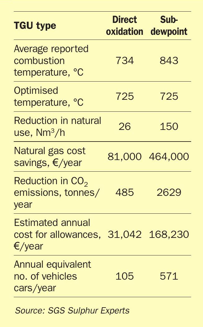
Either one or both of these changes (reducing the inlet CO, and maximising CO destruction efficiency) may be the key to achieving the BAT limit with a combustion temperature of only 725°C. Effects of optimisation were modelled using the direct oxidation and sub-dewpoint TGUs as these had the coolest and hottest combustion chamber temperatures, respectively. The summary is provided in Table 3. The median price for one CO2 allowance on the European Energy Exchange has been around €64 per tonne of CO2 or CO2-equivalent for the majority of 2024. At this price, the CO2 allowance savings alone could be between €31,000 and €168,000 per year, depending on the original starting temperature and the size of the SRU. Based on the five-year historical average cost of European natural gas futures, natural gas savings could be between €81,000 and €464,000 per year. This configuration revamp may be best for those operators using purchased natural gas, or considered as a plan to implement when CO2 allowance prices increase.
Oxygen optimisation
By far the easiest and most accessible optimisation for any incinerator is to manage the excess oxygen in the waste gas – this directly affects the amount of fuel needed and the consequent CO2 production for any temperature operating target. Correctly controlling the combustion requires that an oxygen analyser be installed on the stack or incinerator outlet, ideally where the temperature is cooler. Incinerator burners typically use a chamber temperature measurement to control the fuel supply and combustion air is provided on a stoichiometric ratio basis, or managed manually. The new oxygen analyser can be passive but the most benefit will come from an on-line feedback control system that acts directly on the combustion air supply.
Table 4 shows the results of the oxygen optimisation on incinerators in various TGU types burning natural gas. The subdewpoint systems were not included as all historical data showed oxygen concentrations were less than 5%. It is assumed that these systems would respond similarly to plants without a TGU.
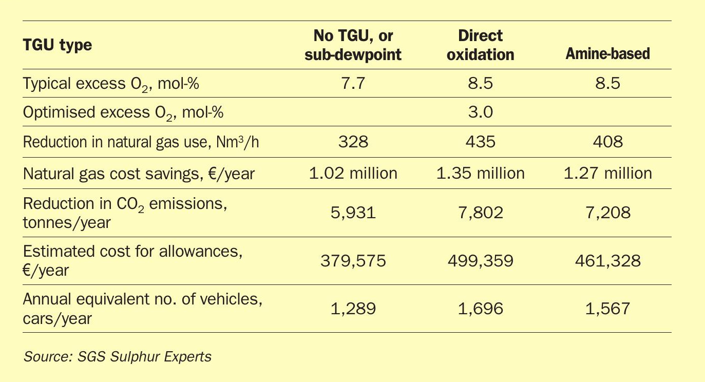
The results show that this simple optimisation can result in a reduction of approximately 390 Nm3 /h of natural gas for a 100 t/d European SRU. This directly translates to savings of approximately €1.2 million per year based on current natural gas futures prices. This will not be realised for those refineries using their own fuel gas. Regardless of the fuel source, this simple optimisation will reduce CO2 emissions by approximately 7,000 tonnes per year. At the current median price of CO2 allowances at €64 per tonne, this translates to potential savings of around €450,000 per year. Alternatively, unused allowances can be sold on the market to generate a true profit. Against the typical cost of purchasing and installing a stack oxygen analyser, the payback period would be very short.
There are many types of oxygen analysers on the market specifically designed to handle the high temperature and other conditions that exist in the SRU incinerator yet requires some care in choosing a technology. For example, zirconia-based oxygen sensors do an excellent job but may give inaccurate readings if there are residual combustibles in the stack. Tunable laser diode technologies would work well in such a service (for example, in catalytic incinerators which do not handle hydrocarbons well), but would have a significantly higher capital cost.
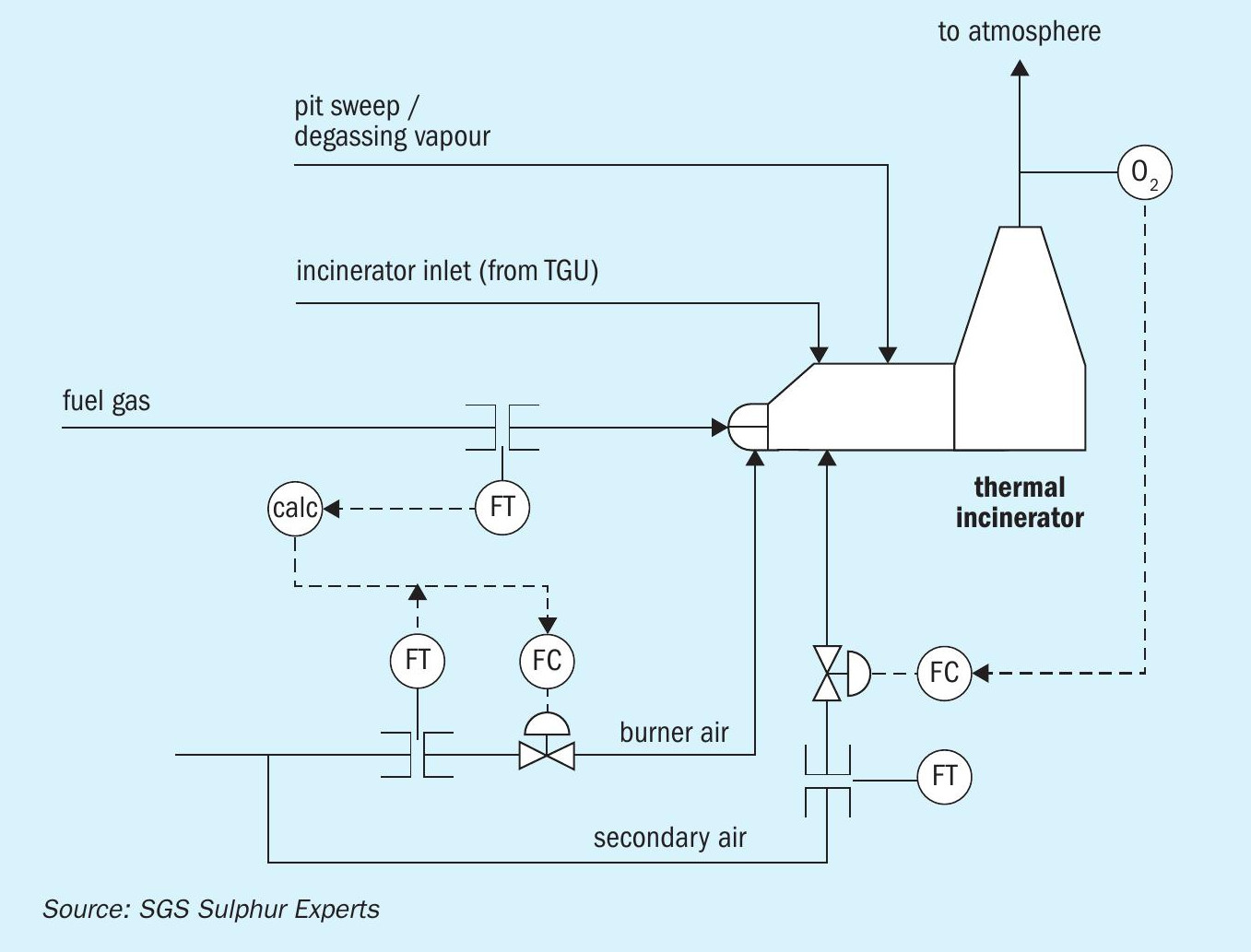
As stated, oxygen analysers are best employed as part of the control scheme of the incinerator. The oxygen measurement should be used to control the combustion air flow rate to the burner. However, this scheme may also run into operational challenges if the control action causes the flame to destabilise. The more desirable arrangement would have a staged-air system (Fig. 8) where the fuel gas enters the burner box with the first portion of air needed for 100% combustion of the fuel. This air flow rate is solely dependent on the fuel gas flow rate and a known air-to-fuel gas ratio. The amount of fuel gas delivered is usually determined by a temperature measurement in the incinerator. The secondary air stream enters downstream of the flame. This flow rate is controlled by a feedback loop using the new stack oxygen analyser. This setup allows the flame to remain stable while still allowing fine control over the excess oxygen. It also helps to maximise the flame temperature (resulting in better combustion) and avoids equipment damage caused by flame impingement on the burner or misdirection. Finally, it is standard industry practice that loss of flame in the incinerator should trip the SRU immediately or within a period of at most 30 minutes. Ensuring flame stability helps to maximise runtime even during transient operation periods.
Summary
European SRU incinerators typically operate hotter and with more combustion air than required. Optimisation of these two parameters will allow operators to reduce their fuel consumption while simultaneously reducing CO2, NOx, and SO3 emissions. The financial benefits are two-fold: direct savings on operating costs from less natural gas usage; and the ability to either reduce the purchase of, or even sell CO2 allowances back to, the European Energy Exchange. The potential savings given in this article are for a theoretical SRU with 100 t/d of inlet sulphur.
Incinerator operating temperature optimisation is complicated by the amount of CO entering the incinerator since it is a regulated species. This affects the large number of non-amine based tail gas technologies in service in Europe, the prevalence of catalytic incinerators which do not reduce CO, and stringent CO emissions regulations based on a well-meaning but misguided understanding of the role of the SRU incinerator. Reducing the amount of CO leaving the incinerator may be possible by retrofitting incinerators with, for example, staged tail gas inlet nozzles to improve mixing and therefore CO destruction efficiency, or by installing an upstream hydrogenation reactor to convert most of the incoming CO to H2 . The incinerator can then be run cooler but this comes with the associated capital and operating costs. Regardless of the chosen route, by minimising the operating temperature it is estimated that fuel use can be cut by between 3 and 24%, correlating to annual savings of up to €464,000 for natural gas. Correspondingly, the estimated reduction in CO2 emissions can be up to 2,600 tonnes per year, roughly valued at €168,000 per year, regardless of the fuel source. These optimisations may best be left for future planning should CO2 allowance prices increase or if CO emission targets become stricter.
Incinerator excess oxygen optimisation is a very accessible tool available to every operator and offers the quickest reward. Simply controlling the excess oxygen alone to 3% can save up to €1.3 million per year in fuel use, and up to €500,000 per year from reductions in CO2 emissions. This is the same as taking 1,500 passenger vehicles offthe road every year. These numbers mean adding the necessary instrumentation and control scheme will pay out very quickly. There are also other possible optimisations around the incinerator that will improve system reliability and minimise unit trips. It is hoped that these potential savings will encourage SRU operators to explore this relatively simple process:
- determine the precise local emission limits for your incinerator;
- determine the concentrations of the controlled species in the SRU incinerator feed gases;
- model and then field test to determine the lowest combination of excess oxygen and incinerator temperature which will achieve the required emission;
- evaluate necessary permit changes or discuss options with permitting authorities;
- change the incinerator operation.
Acknowledgements
The authors would like to acknowledge the many individual European SRU sites that have shared their permits and their understanding of the permitting process with Sulphur Experts over the years. Regional regulations were also collected with the help of the SGS network, and technical information about operation of oxygen analysers is courtesy of Novatech. The authors would like to give thanks for their contributions as well. The authors would also like to acknowledge the historical incinerator studies and incinerator model development conducted by past Sulphur Experts colleagues starting as far back as the 1970s; their work is the basis for much of the modelling presented in this article and has been responsible for significant fuel gas savings and CO2 reductions for over 40 years.
References