Sulphur 386 Jan-Feb 2020
31 January 2020
Hydrocarbon removal from sour water systems
SOUR WATER SYSTEMS
Hydrocarbon removal from sour water systems
Hydrocarbon contamination of sour water streams feeding sour water strippers is a well-known challenge in the refining and gas processing industry. The source of this challenge is the formation of a stable oil emulsion in an aqueous phase that may contain both H 2 S and NH 3 . The typical approach to the problem involves large residence time tanks with the assumption that droplet settling will occur over a long enough time frame. In practice, droplet settling is very slow due to a variety of reasons, and as a result, operators encounter sour water heat exchanger fouling, stripper fouling, hydrocarbon excursions to sulphur recovery units along with other operating challenges. M. Thundyil, D. Seeger and E. McIntosh of Transcend Solutions present a case study of the TORSEP™ oil and solids removal system for contamination removal from a sour water feed stream. The case study illustrates the effect on heat exchanger fouling along with the effect of the variation of several system parameters on operating performance and economics.
Sour water systems can be found in most refineries and gas plants throughout the world. The sour water is generated throughout the facility from many sources and is accumulated in large tanks for treatment in the sour water system. In the sour water system, light hydrocarbons, hydrogen sulphide (H 2 S) and ammonia (NH 3 ) are stripped from the sour water and the stripped gas is often sent to the Claus unit reaction furnace for destruction and conversion to nitrogen and sulphur. Examples of sources of sour water from within the facility include 1 :
- hydrotreater or hydrodesulphurisation units where sulphur-containing hydrocarbons are reacted with hydrogen and H 2 S is formed and the temperature of the hot gas from the reactors are quenched with water to reduce the temperature;
- the reflux water from the regenerator in the amine unit can be a source of ammonia;
- steam is used throughout various processes in the refinery where it may contact NH 3 and H 2 S – when condensed and recovered, the water may become sour and contain H 2 S and NH 3 ;
- wash water used throughout the facility may contact NH 3 and H 2 S and become sour;
- water is recovered in the crude, fluidised catalytic cracker, and coker units, and is also likely sour water.
These and many other sources of sour water are all accumulated from throughout the facility and pumped into feed tanks to be treated in the sour water system. An examination of the various sources of sour water quickly indicates that this water is probably highly contaminated with salts, solid particulates and hydrocarbons. One attempt to handle the contaminants found in the sour water stream is to accumulate the water in large holding tanks in the hope that the solid particulates will settle to the bottom and the hydrocarbons will separate and float on top of the water where it can be skimmed 2 . The solid particles would be removed during turnaround when the tanks may be cleaned. The issue is that the approach does not work well, and solid particulates and hydrocarbon are not separated in the large holding tanks. Instead they are pumped into the sour water system which perpetuates the problems throughout that system and others connected to it. Solving the sour water system contamination problem at its root cause is what inspired the design of TORSEP™ contaminant removal from sour water systems.
Background
A refiner on the US Gulf Coast was forced to clean the heat exchanger in the sour water system approximately every 3-6 months due to fouling. The operators at the facility had come to accept this problem as the normal routine course of operation. During a meeting where Transcend Solutions were reviewing operations and maintenance, it was discussed that operations did not have to accept heat exchanger cleaning every three months as a routine operation, but rather that the problem could be fixed. It was suspected that the problem was not only solid particulate fouling but also hydrocarbon fouling on the surfaces of the heat exchanger. To better define and understand the issues Transcend Solutions took in situ solids loading samples 3 and bottle samples at the sour water system. The results of that testing determined that both problems were occurring.
This refiner originally took the approach of holding the sour water in large tanks with a long residence time (1-2 days), however, even with that residence time, the solids did not settle, and the hydrocarbons did not fully separate from the sour water. As the unit was operated, the hydrocarbons and solids were pumped with the sour water from the tanks to the feed/effluent heat exchanger and eventually the stripper column. The heat exchanger fouled with hydrocarbons and solid particulates sticking to the exchanger surface causing reduced heat transfer efficiency and created the need to be cleaned. To perform the cleaning, the system had to be shut down, drained, purged and cleaned followed by reassembly. The cleaning process typically takes about a week. The complete cleaning process caused the refiner to incur significant operating expense. As a result, the refinery staff were very interested in establishing a solution. It was suggested that they remove the solids and separate the hydrocarbon liquid phase from the water. With a simple, cost-effective contaminant removal system, provided on a rental basis, they could evaluate the approach to solving their exchanger fouling problem and, if successful, install a permanent system in the future.
TORSEP contamination removal system
The system includes the Envision™ emulsion separator for liquid/liquid coalescing where the oil phase is separated from the bulk sour water phase. Upstream of the emulsion separator is an Endur™ Tetra™ separator for removal of solid particulates. The first stage removes solid particulates and protects the downstream emulsion separator from rapid plugging. The two separators are described in more detail in the following sections.
Endur Tetra solid separator
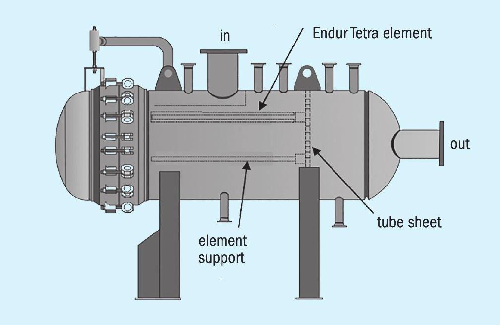
The operating cost of fluid quality management is highly dependent on the choice of element and the vessel size. The vessel needs to be large enough and contain enough filter elements so that there is a reasonable time between filter changeouts. However, the larger the vessel the higher the capital cost, therefore the capex of the vessel is weighed against the opex of filter changeout. For this opportunity Transcend Solutions had an available rental unit and the vessel size resulted in an expected changeout frequency of 1-2 weeks which was sufficient to keep opex low. For solid particulate control a suitable media configuration was applied to capture and retain the particulate contaminants in the inlet liquid flow, at a defined level of efficiency. The media is a locked pore configuration of cross-linked fibres that prevents particulate release under higher differential pressure conditions. A sketch of the solid separator vessel is shown in Fig. 1.
The liquid enters the vessel through the inlet nozzle on top, is diverted by the inlet baffle, and passes through the solid particulate filter elements outside-to-in. The particulate is retained by the media and the clean liquid passes through, into the riser, down the centre riser support, through the tubesheet and into the outlet chamber, exiting through the outlet nozzle to the right in the sketch.
Some of the features of the separator and the filter elements include:
- Preferred flow configuration – The separator elements flow outside-to-in. This is the flow configuration that maximises dirt capture within a given vessel size, thereby allowing the lowest overall operating cost for a given capital expenditure.
- Optimised element configuration – The element maximises contamination holding capacity while also maximising packing density within a housing.
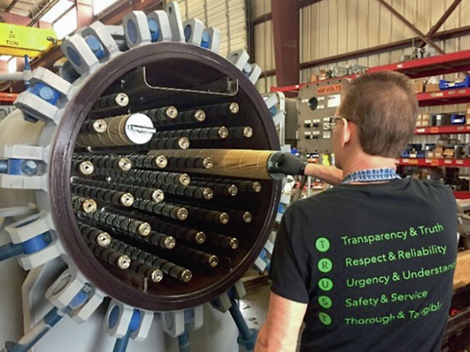
- Ergonomic – The elements are approximately 40″ long and come with an ergonomic handle that allows easy removal and installation. A picture of installing the separator elements is shown in Fig. 2.
- Coreless element configuration – The Tetra element consists of a coreless design, making the element lighter and providing a less strenuous changeout process. The coreless design will also have reduced disposal volume.
Envision emulsion separator
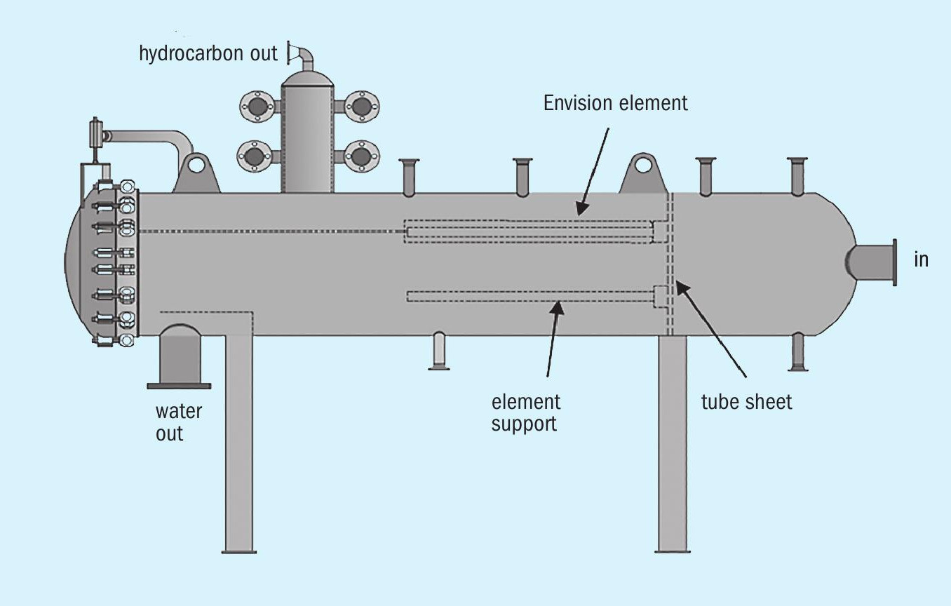
The separator is a single-stage, liquid emulsion separation system. The separator elements can capture and coalesce the small discontinuous phase droplets from a continuous phase that may be aqueous or hydrocarbon in nature. In this case the refiner needed to remove hydrocarbon from the sour water. A sketch of the emulsion separator vessel is shown in Fig. 3.
The liquid enters the vessel through the inlet nozzle located on the right in the sketch. The liquid travels through the tube-sheet, down the riser and through the separator element inside-to-out. As the liquid passes through the media of the separator element, the small droplets of the hydrocarbon phase (discontinuous phase) are captured by the tight media where they are retained until they come into contact with additional hydrocarbon droplets and coalesce into larger droplets. Once the droplets coalesce and grow into large enough droplets, they force their way through the media as very large droplets that readily rise through the water phase and collect in the boot on the top of the vessel. The boot is shown at the top left of the sketch in Fig. 3. The hydrocarbon exits through the nozzle at the top of the boot and the water exits from the nozzle at the bottom, shown on the bottom left in the sketch. A baffle over the outlet helps ensure the longest possible separation time for the hydrocarbon droplets to rise to the top of the vessel rather than be drawn out with the water flow. The residence time is typically of the order of seconds rather than minutes, and is dependent on the media velocity, and densities and viscosities of the two fluids.
The emulsion separator elements offer the following benefits:
- Applicability – The coalescing separator elements will meet a broad range of physical and chemical resistance requirements while allowing very high efficiency separation of aqueous/ hydrocarbon, or hydrocarbon/aqueous dispersions.
- Long online life -Without particulate fouling, the elements are merely reclassifying liquid droplets, and will have an extraordinarily long online life.
- Ergonomic – The liquid/liquid coalescing vessels are preferentially oriented horizontally, eliminating the need for expensive ladders and platforms, while making it easy for operators to replace elements.
- Lower capital cost – Since the coalescer is a single-step process, with liquid disengagement occurring once large droplets are created, the pressure vessel size is reduced by an order of magnitude relative to conventional corrugated plate or other coalescing devices.
With matched particulate removal from solid separators upstream (prefilters), the emulsion separator elements generally will remain in service for six months to one year, possibly longer.
Performance evaluation
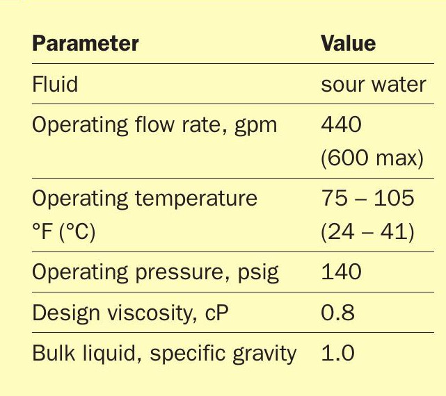
The parameters for the installation are summarised in Table 1. The system was installed on a rental basis to demonstrate the effectiveness to the customer. The system could handle a maximum of 600 gpm inlet flow, however the customer’s sour water system only operated at 440 gpm.
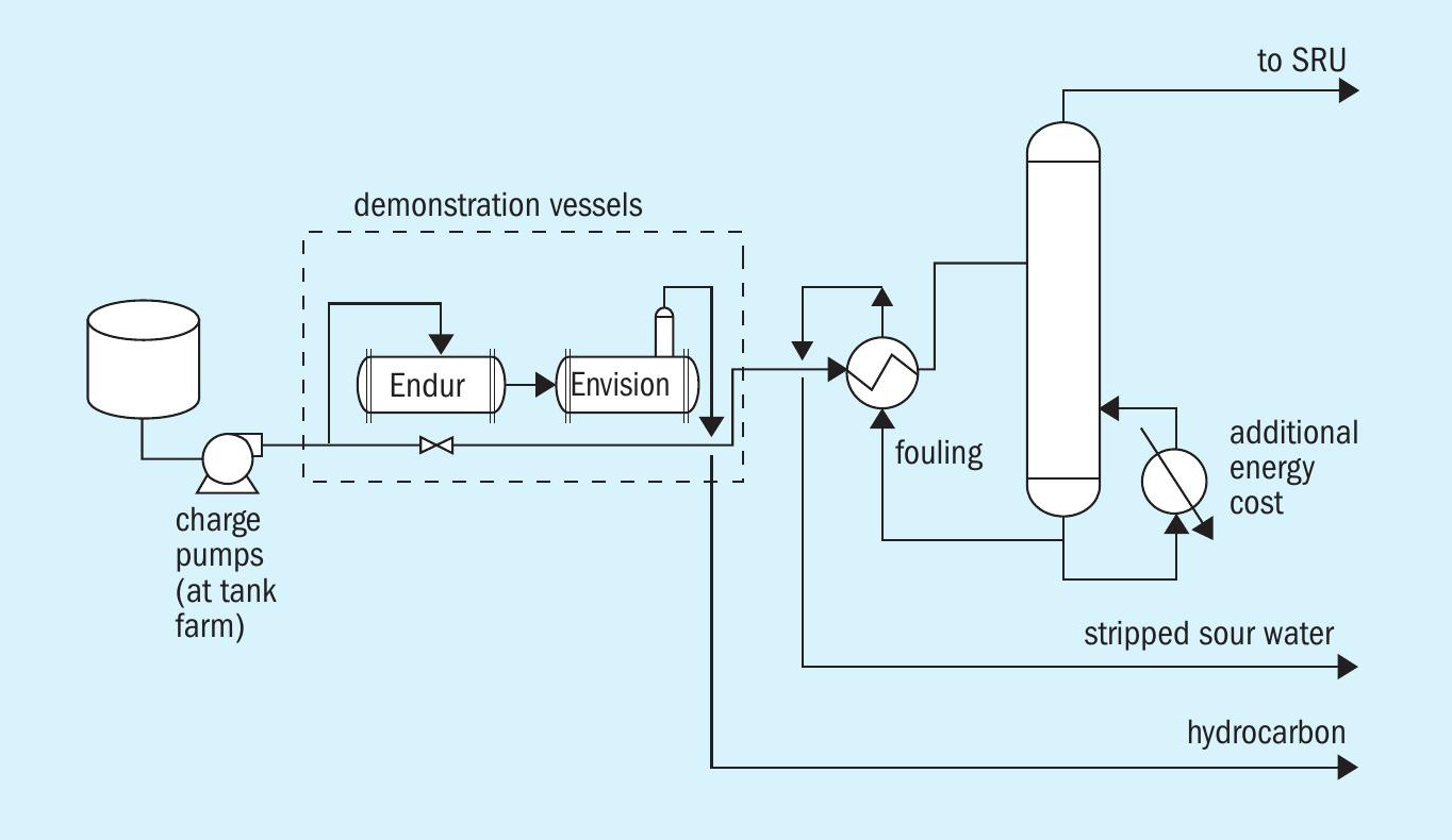
A process flow diagram of the system is shown in Fig. 4.
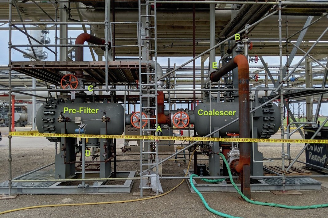
The equipment configuration installed at the refinery is shown in Fig. 5. The system was started in February 2019 and has operated near continuously since that time. The only time the system has been bypassed is for cleaning and element changeout. As shown, the system was installed with one solid separator and one emulsion separator, therefore during change out of the elements in either vessel, both vessels were put into bypass. In an optimised installation it is advised to have two solid separators so that when changing out those filters, the emulsion separator does not have to be put into bypass.
The performance evaluation criteria for the system were:
- impact on heat exchanger fouling;
- amount of hydrocarbon recovered;
- filter changeout frequency.
Impact on heat exchanger fouling.
As discussed previously, the pressure drop (dP) across the heat exchanger in the sour water system continuously rises until the operators are forced to shut down and clean the exchanger. The data, provided by the refinery (Fig. 6), shows that the constant upward trend of the sour water exchangers dP stopped within minutes of bringing the system online. Following start-up, the upward trend stopped and even slightly reversed trend. The dP has remained nearly constant since the start-up and the refiner has not had to shut down to clean the heat exchanger.

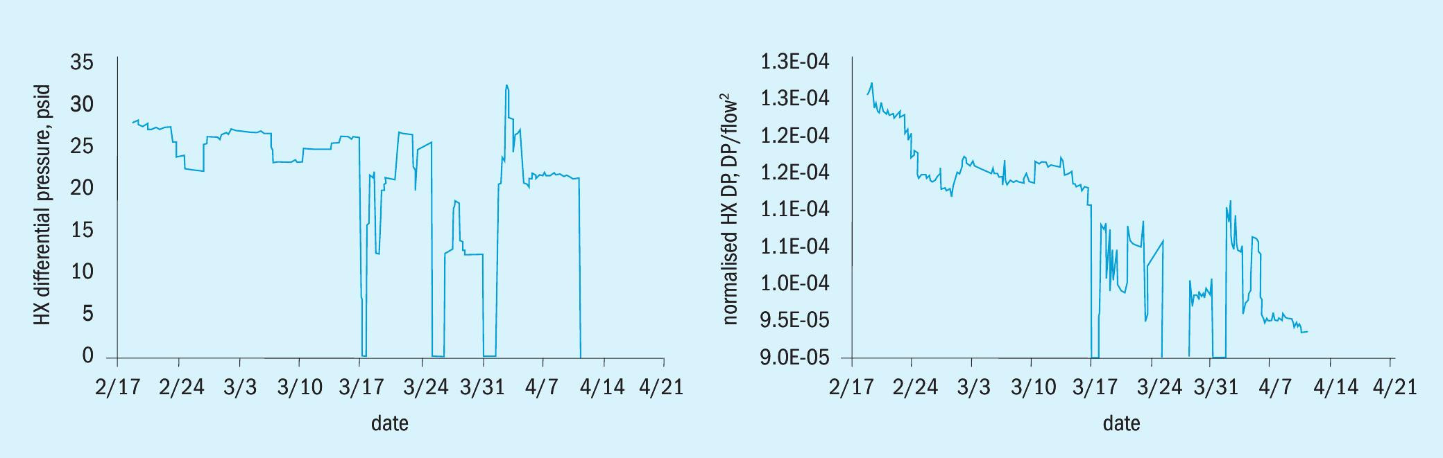
The dP of the heat exchanger over time is shown in the graph on the left in Fig. 7. After the start-up of the solids and emulsion separation system, the operators were able to raise the flow rate through the exchanger because the dP was no longer rising. When the flow rate is increased the heat exchanger dP will rise due to the increased flow. In addition, there are fluctuations in the flow rate during routine operation. Since differential pressure is related to flow, and the flow through the unit has increased and fluctuated, the true trend in differential pressure is much clearer when normalised for flow, which is shown by the graph on the right in Fig. 7. The graph of the dP normalised negates the effect of the flow rate increase and shows that the dP consistently dropped over the entire time period and eventually leveled out. The system has not experienced heat exchanger fouling or DP increase since the start of the TORSEP solid and emulsion separator operation.
Hydrocarbon recovery
Hydrocarbon recovery can be determined by plotting a graph of the level of the liquid/liquid interface in the boot, and the valve-percent-open of the boot level control valve (the “dump” valve). These graphs are shown in Fig. 8, with the boot interface level as a line and the valve percent open as a column graph.
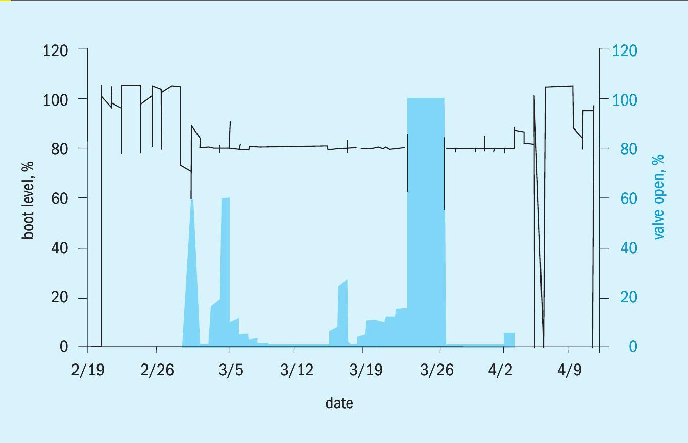
In operation, the oil level in the boot builds until it reaches 80%, at which point the valve opens and oil is drained from the top of the boot. The frequency of oil dumping is not consistent. An “upset” condition can be seen around 3/25-3/27 when the valve is fully open and oil level drops below the 80% mark. The refiner has not shared an explanation of that upset. Typical process upsets in sour water systems have been previously noted to be related to level control failures, turnarounds, power failures, and weather among others.
The solid separator elements were changed out every ten days on average since February. The coalescing separator elements were changed out once since start-up. The changeout frequency met the expected target and the customer is satisfied.
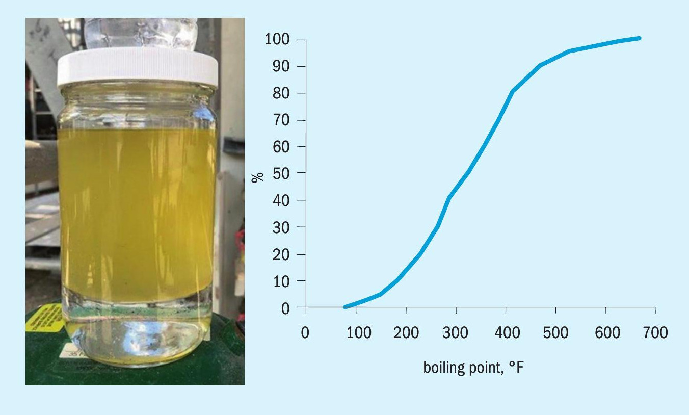
Recovered hydrocarbon
A picture of some of the recovered hydrocarbon is shown in Fig. 9. Its boiling range was determined by simulated distillation, illustrated in Fig. 9. The boiling range extends from 80-700°F (27-371°C). The specific gravity was measured at 0.8.
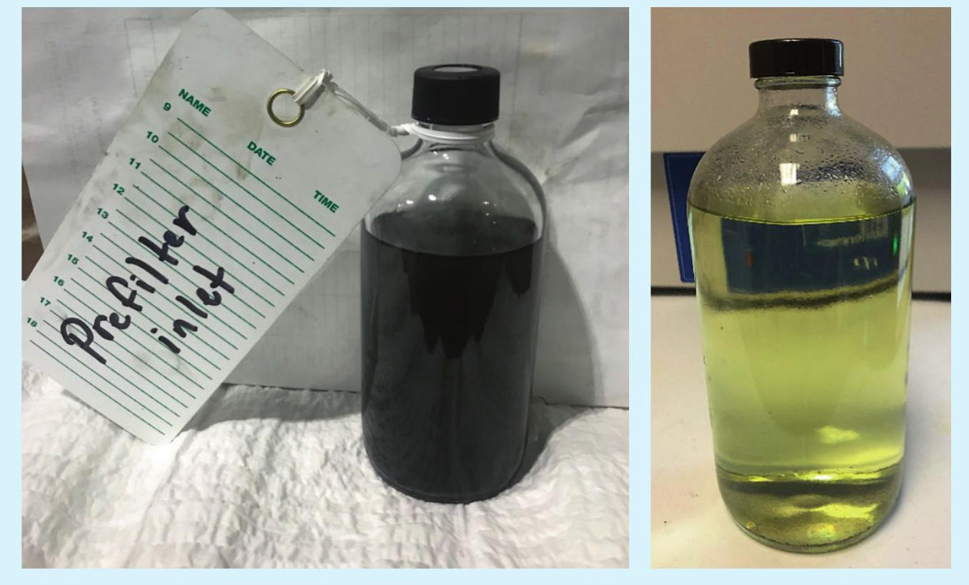
Summary
In summary, a picture is worth a thousand words. Samples taken from the inlet and outlet of the system are shown in Fig. 10. The picture on the left is a sample of the inlet which has hydrocarbons and solid particulates and the picture on the right is taken from the water outlet and shows only a clear water phase.
The performance evaluation successfully demonstrated that heat exchanger fouling was mitigated immediately upon start-up of the hydrocarbon and solids removal system. Hydrocarbon recovery was demonstrated, and filter changeout frequency was validated as reasonable and acceptable by the customer, i.e., the solid particulate filters did not have to be changed out more often than expected. The TORSEP system was a success to such an extent that the refiner is purchasing the rental system. In conclusion, this paper illustrates a technique that can allow sour water stripper units to effectively remove solid and hydrocarbon contamination, and thereby allow the stripper columns to operate as designed, without exchanger fouling and likely without hydrocarbon excursions to the sulphur recovery unit.
References