Sulphur 387 Mar-Apr 2020
31 March 2020
Improved sulphur degassing
LIQUID SULPHUR DEGASSING PROCESS
Improved sulphur degassing
Fluor/GAA continue to strive to improve the performance of the D’GAASS out-of-pit liquid sulphur degassing technology based on commercial operating experience and ever-changing environmental emissions regulations. T. Chow and S. Fenderson of Fluor Energy & Chemicals/ Goar, Allison & Associates discuss operating experience that has led to the improvements of the new patent-pending third generation D’GAASS 3G technology.
All product sulphur from modified Claus process sulphur recovery units (SRUs) contains residual H2S; some as dissolved H2S and some in the form of loosely chemically bound polysulphides, H2SX . The total residual H2S concentration is influenced by the H2S vapour concentration (partial pressure) and the temperature at which the sulphur product condensed. As SRUs are pushed to and beyond their design capacities, the H2S content of the product sulphur increases. Oxygen enrichment also results in higher residual H2S. The average H2S concentration in typical SRU product sulphur is 250-350 ppmw. Some H2S is released during sulphur storage, handling, and transportation.
Several factors contribute to the release of H2S from liquid product sulphur. Primary contributing factors to the release of H2S from liquid sulphur are low H2S concentration in the gas above the liquid sulphur, mechanical agitation, cooling, and time. The equilibrium ratio of H2S to H2SX is dependent on temperature. The equilibrium ratio of H2S/H2SX is about 1.5 at 155°C and 10 at 125°C. Over time, dissolved H2S will desorb into the gas phase; physical desorption is favoured by low H2S gas concentrations. As H2S is desorbed, some H2SX is converted to H2S to maintain the equilibrium H2S/H2SX ratio. The conversion of H2SX to H2S is relatively slow, and the overall H2S release rate can be controlled by the rate H2SX is converted to H2S.
The released H2S results in potential safety hazards from the toxic H2S gas and potentially explosive concentrations of H2S in air. Formed solid sulphur product from undegassed sulphur is more friable (prone to fracture and create dust). The release of H2S from liquid and solid sulphur results in noxious odours. Undegassed sulphur is more corrosive. Degasification of liquid sulphur controls most of the above listed problems.
Sulphur degassing
Sulphur has been degassed commercially since the 1980s, but continues to be more widely applied as the emphasis on minimising sulphur emissions and improving safety have become higher priority items. There are two major classifications of sulphur degassing processes:
- in-pit/tank atmospheric pressure processes;
- out-of-pit processes.
Out-of-pit processes have the advantage of being able to operate at pressures high enough to allow the H2S containing effluent air to be directly routed to the SRU thermal stage or tail gas clean-up unit.
D’GAASS process history
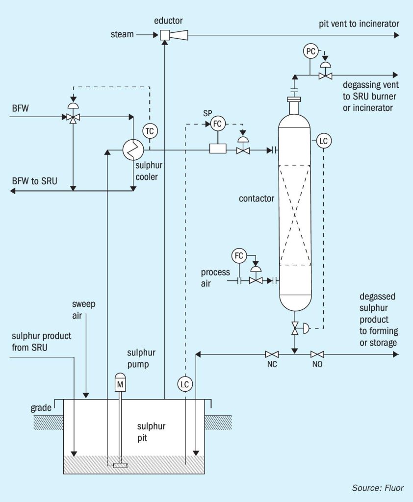
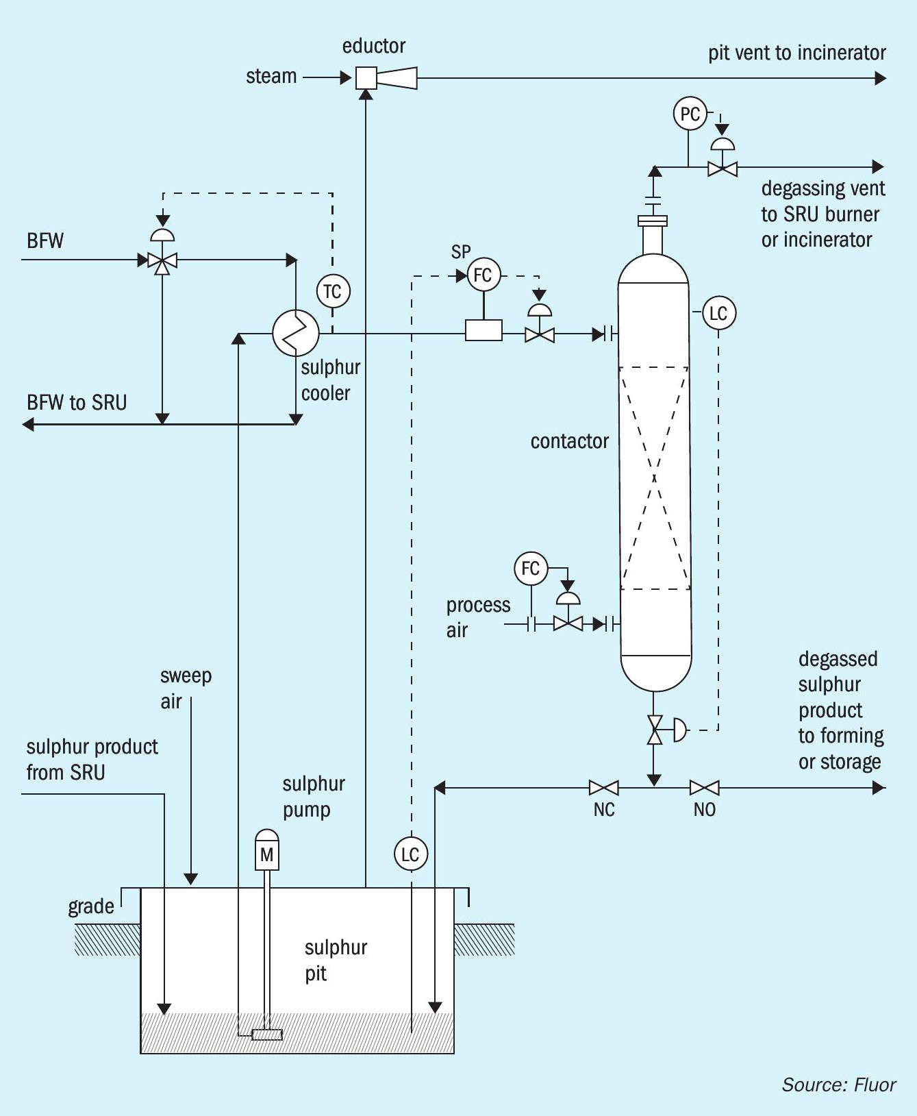
The D’GAASS process (Fig. 1) is an outof-pit process that was introduced to the sulphur industry in 1997. The D’GAASS process was developed on the idea that degassing could be accomplished primarily through the oxidation reaction of H2S and H2SX by oxygen dissolved in liquid sulphur. The oxidation reaction had been recognised as contributing to the overall degassing performance in the in-pit atmospheric pressure processes. The D’GAASS process operates at elevated pressure to increase the rate that oxygen dissolves in sulphur and increase the equilibrium concentration of oxygen in sulphur. This results in greatly reduced required degassing residence time (less than one hour). Sulphur is pumped from the sulphur rundown pit to the degassing contactor. Sulphur enters near the top of the contactor. Process air enters near the bottom of the degassing contactor. Sulphur and process air flow countercurrently across vapour liquid contacting internals through the contactor. The contactor vessel is sized to provide the required residence time based on the sulphur production rate, feed H2S concentration, operating pressure, and process air feed rate.
Degassing residence time is maintained by controlling the level in the degassing contactor by regulating the rate degassed sulphur exits the bottom of the contactor; the operating pressure is controlled by regulating the overhead gas rate exiting the vessel. Operating under pressure allows the overhead gas routing to the SRU thermal stage, oxidation type tail gas clean-up units, or the plant incinerator. The degassed product sulphur flows to storage, forming, or loading without additional pumping.
Since the introduction and installation of the original units, several modifications/improvements have been incorporated into current D’GAASS unit designs. The original units operated at higher pressures than current design. Also, the original units utilised a bed of oxidation catalyst below the process air entr y point. These and additional changes are discussed in more detail.
D’GAASS operation history
The D’GAASS process degassing performance has been very good. All of the over 100 licensed units have met their performance guarantees. There have been a few locations that have experienced some operational issues. The most significant problem has been corrosion in the upper contactor area and overhead piping upstream of the pressure control valve. Level control has been a problem in some units.
Overhead corrosion
Corrosion in the upper contactor and overhead piping is a result of water condensation in the presence of H2S, SO2 , O2 , and sulphur vapour. Water is present from the oxidation reaction of H2S and H2SX . The presence of oxygen results in a very aggressive corrosive environment when water condenses. Operation under pressure improves degassing performance, but also increases the water dew point. It is therefore essential to maintain the temperature of the contactor shell and overhead piping above the water dew point temperature. Improvements in design to reduce the corrosion potential are discussed in the upgrades section.
Level control
Some units have had problems controlling the level in the contactor. Most of these locations have had problems because radar type level transmitters have been installed instead of the specified capacitance type level transmitters. GAA has only had long term success with capacitance, admittance and nuclear type level transmitters for direct measurement of the liquid level in the vessel. There is a foam disengaging layer on top of the liquid sulphur as air bubbles exit the liquid phase. This foam layer can act like an acoustical tile and affect the radar signal. This is true for both conventional and guided wave radar. The foam layer can be tuned out for a set of conditions, but the foam layer can be affected by multiple impurities, particularly dirt and oils that affect the foam layer thickness and density.
D’GAASS upgrades
When there have been issues with the operation of D’GAASS Units, GAA engineers have worked to develop solutions to address the issues. Some of the major design upgrades in D’GAASS units are addressed below.
Operating pressure
Some of the early D’GAASS units operated at pressures that required utilisation of 2-stage compressors to supply the process air. Through performance testing, it was confirmed that the operating pressure could be reduced to allow using single stage compressors while maintaining less than 10 ppmw residual H2S in the product sulphur if some design parameters were modified. Lowering the operating pressure also had the positive effect of lowering the water dew point in the overhead gas stream.
Dry air
In earlier installations, some D’GAASS units have experienced corrosion in the upper contactor vessel and overhead piping although the process conditions did not indicate that corrosion could occur. Closer evaluation of the corrosion points indicated it was occurring at cool locations in the vessel and piping such as lifting lugs, pipe supports, etc. For the type of corrosion that was observed, there must be a liquid phase (water) present. Water cannot be eliminated from the process because it is a reaction product from oxidation of H2S and H2SX . However, the amount of water from reaction is much less that the amount of water entering with the process air in locations utilising dedicated air compressors to supply the air. This was particularly the case in locations with normally high to moderate ambient temperatures and high relative humidity. Therefore, the process air requirement was changed to utilise dry, instrument air quality, air. This significantly lowered the water dew point in the overhead gas stream and reduced the potential for corrosion.
Fully steam jacketed contactor
Corrosion issues were a result of cold locations in the contactor and overhead piping where water could condense in the presence of acid gases H2S and SO2 . With oxygen present, the corrosion was likely sulfurous acid corrosion. Higher alloy metallurgy including Hastelloys were tried, but rapidly corroded in cold locations. Contro-Trace elements and panels were utilised on the upper contactor and overhead piping, but ControTracing leaves gaps and sections without direct heat, and if the ControTracing is removed for maintenance, it frequently is not reinstalled correctly.
To minimise the potential for cold spots and resulting corrosion, current designs include full steam jacketing of the contactor vessel and overhead piping through the pressure control valve. This assures that there will not be areas that are not directly heated and minimises the potential for corrosion. In the critical overhead area of the contactor and overhead piping, medium pressure steam (7-10 barg/100-150 psig) is being utilised for jacket heating. Higher pressure steam provides additional temperature margin (about 20-35°C/35 ‐65°F) above standard 3.5 barg (50 psig) steam and maintains temperatures above the water dew point.
D’GAASS 3rd generation objectives
D’GAASS design engineers are continually looking for improvements in the reliability and performance of the degassing process. Through better understanding of the potential advantages of solid catalyst promoting the decomposition of H2SX , objectives for process improvement were established. These include:
- minimise catalyst attrition from fluidisation/agitation of the catalyst bed;
- reduce the process operating pressure to improve H2S stripping from liquid sulphur and corrosion potential;
- reduce the required residence time for sulphur degassing through H2SX catalytic decomposition and improved H2SX stripping;
- easily upgrade existing D’GAASS units with new developments.
Methods to achieve objectives
Avoid upward flow of sulphur and air across catalyst bed
The primary issue with another out-of-pit process has been catalyst attrition from upward flow of sulphur and air through the catalyst. The density of sulphur and the particle density of alumina catalyst are very similar. Therefore, there is a significant buoyant effect from liquid sulphur and upward flow of sulphur and air causes catalyst particles to float/fluidise and grind away at adjacent catalyst particles. This effect is countered by having sulphur flow downward or across the catalyst bed.
Isolate catalyst bed from stripping gas flow
Stripping gas is required to remove H2S released from the liquid sulphur. However, upward flow of stripping gas bubbles can promote movement of catalyst particles, which causes attrition of the catalyst. In the latest design, stripping gas is isolated from the catalyst bed. Sulphur flows across the bed to promote decomposition of H2SX , but air does not flow counter currently to the sulphur until it exits the catalyst bed.
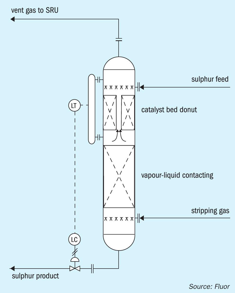
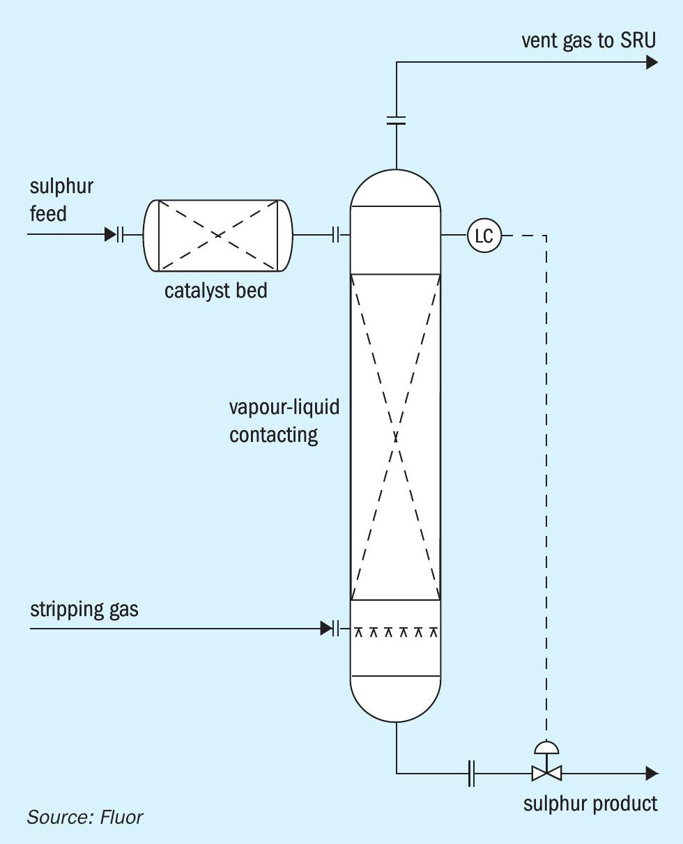
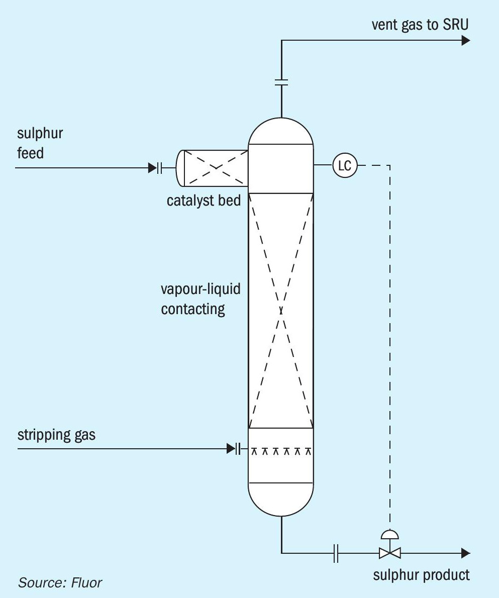
There are alternative configurations that can accomplish the isolation of the catalyst bed from the stripping gas. Fig. 2 illustrates an option in which the catalyst bed is located in a donut arrangement above the main sulphur liquid level. Sulphur is distributed around the donut and gravity flows downward through the catalyst bed. Stripping gas disengages from the main liquid sulphur pool and flows upward through the stand pipe in the centre of the catalyst bed. Fig. 3 shows an arrangement in which sulphur flows through the catalyst bed that is located in a separate vessel before entering the main stripping vessel. Fig. 4 shows an arrangement in which the catalyst bed is located on the side of the stripping vessel. Sulphur flows horizontally across the catalyst bed before entering the main stripping section of the vessel.
Alternative level measurement methods
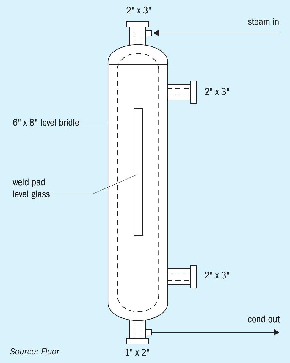
The donut arrangement for the catalyst bed shown in Fig. 2 requires a different level measurement configuration than the capacitance probes that have been utilised in D’GAASS units and inserted through the top of the contactor vessel. The best arrangement for level measurement with the catalyst donut arrangement is indirect through use of an external level bridle, see Fig. 5. The bridle is fully steam jacketed (nozzles, valves, and main body). The external level bridle can obviously be used for the other configurations shown in Figs 3 and 4.
The external level bridle allows several options for level measurement, and allows easier application of different types of devices for control and shutdown functions. Level transmitter options include conventional differential pressure transmitters, bubbler type differential pressure, radar, and capacitance. The level in the bridle can also be visually observed by using a weld pad level glass for the main body. A weld pad with a radius curve to match the body is recommended to minimise stress on the glass.
Summary
The D’GAASS 3rd generation process takes advantage of solid catalyst dissociation of H2SX to H2S and sulphur to enhance stripping H2S from Claus SRU product sulphur. Catalyst attrition is avoided/minimised by utilising sulphur down flow or cross flow across the bed and isolating the bed from stripping gas flow. Stripping is enhanced by operating at lower pressures and sulphur residence times than previous D’GAASS units. Existing units can be retrofitted to 3rd generation operation and at the same time, the processing capacity.
In addition, the D’GAASS liquid sulphur degassing unit can easily be designed and fabricated in the form of a truckable modular unit to mitigate expensive field installation and shorten EPC schedule. Modular units up to 800 t/d require a plot area of only 5 m x 10 m.