Sulphur 387 Mar-Apr 2020

31 March 2020
Processing ammonia in SRUs
AMMONIA INCINERATION
Processing ammonia in SRUs
R. Kranenburg of Duiker discusses the latest applications of SCO units in refineries and petrochemical complexes. The SCO unit is typically integrated in the sulphur recovery unit and is intended for processing ammonia, while also treating the tail gases from the upstream SRU.
Duiker has developed its ammonia incinerator to meet market demands for a simple and reliable process that converts ammonia (NH3 ) in refineries and petrochemical plants into nitrogen and water. The Stoichiometry Controlled Oxidation (SCO) unit is typically integrated in the sulphur recovery unit (SRU) and is intended for processing ammonia, while also treating the tail gases from the upstream SRU. The heat generated during the oxidation of NH3 is reused in the downstream thermal incinerator unit to preheat the SRU tail gases. Although the temperature of the tail gases is increased significantly, a small support burner on the thermal oxidiser is often installed to provide additional heat to bring the tail gases to the required incineration temperature.
Today, several SCO units are in operation under various process conditions which prove its ability to completely decompose NH3 . In stark contrast to uncontrolled ammonia combustion which can easily generate thousands of ppm of NOx emissions, the NOx emissions from the SCO unit can easily meet environmental regulations without further treatment. The SCO unit can realise NOx emissions in the range of 50-70 ppm @ 3% O2 dry.
History
The SCO technology was developed and commercialised in the early 2000s. The first unit was developed for a refinery in Europe with an existing SRU facility. This facility was designed for processing a regular feedstock in terms of sulphur content which had been imported by the refinery for a long time. However, the attractive price of heavier feedstocks later led to the refinery switching to heavier feedstocks. As a consequence the SRU capacity had to be debottlenecked to enable the plant to handle the extra H2 S and ammonia in the feed. Since the plant was only a few years old, it was decided to make modifications to the existing SRU capacity rather than replacing the existing plant. Plot space limitations were also an important consideration for the refinery. After several plant studies had been made, it was determined that the best method was to integrate a dual-stage SWS unit (dual-stage sour water stripper unit) with an SCO unit. Obviously the strategy behind implementing the dual-stage SWS unit is to separate the H2S from the NH3 so that the NH3 can be routed to the SCO unit in order to reduce the feed gas flow to the main reaction furnace. This creates extra space for processing the extra H2S from the heavier feedstock in the SRU.
Fundamental principle of the SCO unit
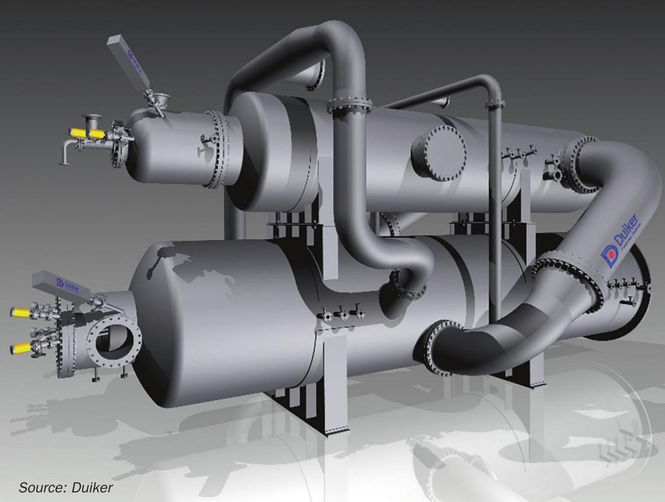
The most widely supplied type of SCO unit is based on two connected combustion chambers which are positioned one on top of the other (see Fig. 1) to save plot space at the plant site. The ammonia-rich gas from the dual-stage SWS unit enters the first chamber via a dedicated ammonia burner, in which the ammonia is decomposed to nitrogen and water under reducing conditions. The hot effluent exiting this reducing reaction zone is then routed via interconnecting pipes towards the second chamber (Fig. 2), in which the gases are mixed with the relatively cold tail gases from the tail gas treating unit for final treatment in the thermal oxidiser section of the SCO. Additional heat is generated by a support burner on the oxidising chamber to heat up the tail gases to the desired incineration temperature. Regardless of the presence of SRU tail gases or any other gas streams that may be routed to the SCO, an oxidising section is always required to complete the reactions and ensure that there are no unreacted species from the reducing combustion zone. All SCO units are followed by a downstream waste heat boiler which recovers the heat from the process, potentially allowing it to be used in the dual-stage SWS unit to separate the amines in the regeneration column.
Economical evaluation
In recent years more SCO units have been supplied to other refineries. Unlike the first unit all subsequent units have been integrated in new grass roots plants due to the favourable economics of this configuration.
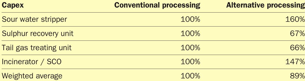
In the following evaluation (Table 1) a 100 t/d SRU is considered with a mixed feed containing approximately 22 vol-% ammonia. The SRU has two catalytic stages and the TGTU is a non amine system, allowing 99%+ sulphur recovery.
The conventional way of processing ammonia via the SRU forms the base case and the costs of the individual components are set at 100%. The impact on capex for the alternative design was then evaluated. The SWS capacity was roughly 135 m3 /h and converting it to a two-stage design resulted in a capex increase of approximately 60%. In the conventional processing route, the process gas capacity exiting the main reaction furnace was approximately 22,200 kg/h. In the alternative processing scheme the process gas capacity exiting the main reaction furnace was approximately 14,250 kg/h. The resulting decrease in capex of the SRU and TGTU was about 33%. The capex for the SCO unit was approximately 47% higher than the conventional incinerator. The weighted average of these four components yielded an 11% more favourable capex for the alternative processing route.
The opex evaluation was driven by three main items: fuel, electricity and steam. As ammonia is utilised as the fuel for the incinerator in the alternative processing route, 465 kg/hr of fuel gas is saved in the alternative design. With regard to electricity, the main impact comes from the blower consumption, which is reduced by approximately 0.12 MW/hr in the alternative route. The combined sum equates to annual savings of approximately e450,000. The steam balance in the alternative processing route is of course less favourable than in the original design from both a consumption and production standpoint. More steam is consumed due to the dual-stage SWS unit requirements and less steam is produced due to the reduced hydraulic load of the SRU. As no steam costing data was available for this specific plant, the economic impact is not evaluated.
Although it is possible to combust high concentrations of ammonia in the main reaction furnace of a SRU, there are technical considerations (namely achieving a high enough temperature), which favour alternative processing of the ammonia. For feed streams containing high amounts of ammonia, the hydraulic load involved with processing this ammonia in the SRU and thus the capex, definitely favour alternative processing. Through the use of a Duiker SCO unit, licensors and end-users have the opportunity to process the ammonia stream in a separate ammonia incinerator rather than the main reaction furnace, leading to significant savings in capex, while providing a more reliable integrated plant.
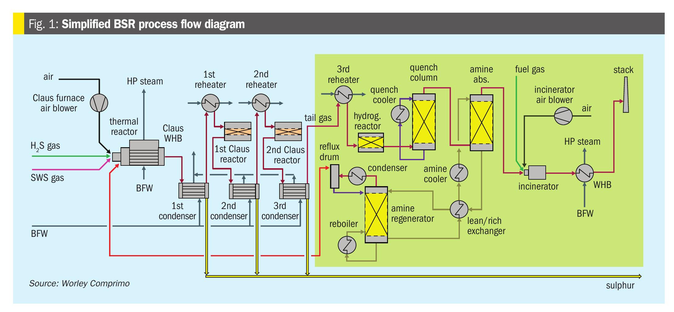
Fig. 3 shows a schematic of a SRU line up with TGT unit in which SWS gas is treated in the SRU.
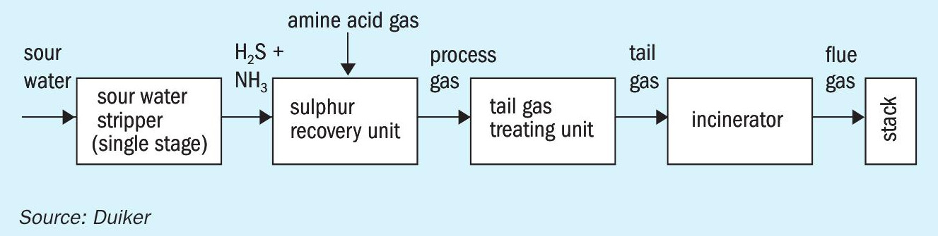
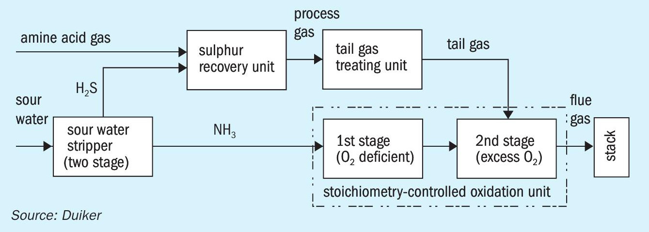
Fig. 4 shows a SRU line up with SCO unit for treating the ammonia containing stream from the dual-stage SWS unit.
Ammonia use for fuel or fertilizer
As mentioned earlier, the ammonia from the dual-stage SWS unit is used as fuel in the SCO unit. Since the heat released by the combustion of ammonia is used for heating up the tail gases from the SRU, the quantity of fuel gas used in the thermal oxidiser will be greatly reduced. This also has a positive effect on the reduction of CO2 emissions from the stack. However, despite these benefits one could argue that since the NH3 is separated from H2 S by the dual-stage SWS unit, it would make more economic sense to use it as a feedstock for creating ammonia fertilizer rather than using it as a fuel for the SCO unit. There are indeed a small number of plants in the world where ammonia is transported via a pipeline from the refinery as a raw material for creating fertilizer. Unfortunately the economics of this routing are not known at the time of writing this article.
Ammonia is produced on an industrial scale via the Haber Bosch process. By comparison, the amount of ammonia produced as a by-product in refineries is negligible and must be completely free of H2 S before it can be safely used as a raw product for further processing. From an economic point of view the transportation of ammonia is only considered feasible if there is ammonia demand in the direct vicinity of the refinery.
Current developments
In the most recent application of SCO technology it has been integrated in a grassroots petrochemical complex for handling an ammonia-rich stream from an upstream process containing a few percent of sulphur. Since oxidising this stream in a standard thermal oxidiser would lead to high NOx and SOx emissions from the stack, the SCO routing was further evaluated by the licensor in combination with a SO2 scrubber to handle this stream. Further research is currently being carried out to investigate the effect of greater amounts of sulphur on the operation of the SCO unit and how this affects the decomposition of ammonia. Results to date are positive indicating that larger amounts of sulphur can be processed by the SCO which could make it an attractive alternative for directly processing gases from a single-stage SWS unit. Duiker also sees the potential for realising even lower NOx emission values.
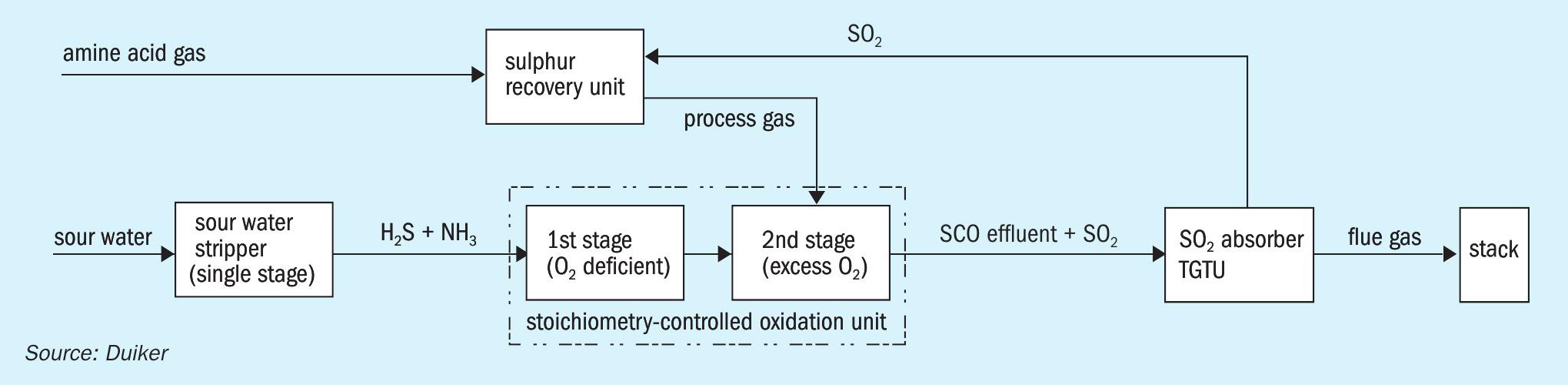
Fig. 5 shows a SRU line up with a SCO unit for treating sour water stripper gas from a single-stage stripper. An SO2 absorber is attached to remove the sulphur species from the outlet stream of the SRU (without TGT) and to remove the sulphur species from the outlet stream of the SCO unit.
Acknowledgements
The author would like to thank the following for their kind contribution to this article: Rob Stevens, VP of Yara Norway on the production of NH3 , Thomas Chow, VP of Fluor California on NH3 as a by-product in refineries, and Floor Huisman of Sulphur Experts, The Netherlands, on the processing of NH3 .