Fertilizer International 496 May-Jun 2020
31 May 2020
Sulphuric acid plant design and materials
SULPHURIC ACID TECHNOLOGY
Sulphuric acid plant design and materials
We highlight recent innovations in sulphuric acid plant design and construction. NORAM and CPPE are offering a new hybrid sulphuric acid process. KVT, meanwhile, has upgraded its wet sulphuric acid technology to reduce capex, opex and emissions. Improved methods of construction and new materials from Koch Knight are also helping to optimise acid tower design
Increasingly stringent emissions regulation are an increasing challenge, both for currently operating sulphuric acid plants and those under development. To help meet new emissions targets for sulphur-containing gases, NORAM in partnership with CPPE have introduced the Hybrid Sulphuric Acid Process (HSAP).
Environmental and other challenges
Environmental regulations worldwide have become increasingly stringent with narrower operating limits and increasing penalties for non-compliance. There is a requirement for all sulphuric acid plants – sulphur-burning, metallurgical, acid regeneration or acid gas types – to achieve very low steady-state emissions of less than 50 mg/Nm3 (SO3 , H2 SO4 mist and SO2 ). Low emissions limits must also be met and maintained during start-up and process upsets. Plants also need to be able to continue manufacturing sulphuric acid to commercial specifications while complying with these environmental constraints.
Other important operational considerations and design challenges at sulphuric acid plants include:
- Chemical integration. Any scrubbing processes that can be integrated to produce commercial-grade sulphuric acid are attractive to operators.
- Energy recovery and efficiency. The economics and the sustainability of large-scale industrial operations ultimately depend on energy efficiency. Processes that offer improvements in energy recovery are therefore desirable.
- Operability. Operators place great store in processes that are safe and whose mode of operation is well understood.
The HSAP process
To address and overcome these challenges, NORAM and CPPE formed an exclusive alliance to develop the Hybrid Sulphuric Acid Process (HSAP). This innovative process provides a comprehensive solution for the abatement of SO2 gases in industrial applications (Sulphur 383, p44).
HSAP increases the production of sulphuric acid and steam while at the same time reducing SO2 , SO3 and H2 SO4 emissions – and does this without requiring additional reagents or raising operating costs.
HSAP is based on standard single-contact, single-absorption sulphuric acid technology. It combines modern NORAM equipment designs with CPPE’s Sulfacid® reactor. In the process, acidic effluent from the Sulfacid® reactor is recycled to the contact section in a closed loop. This is advantageous as it avoids the need for added chemicals and eliminates waste by-products.
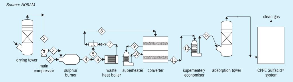
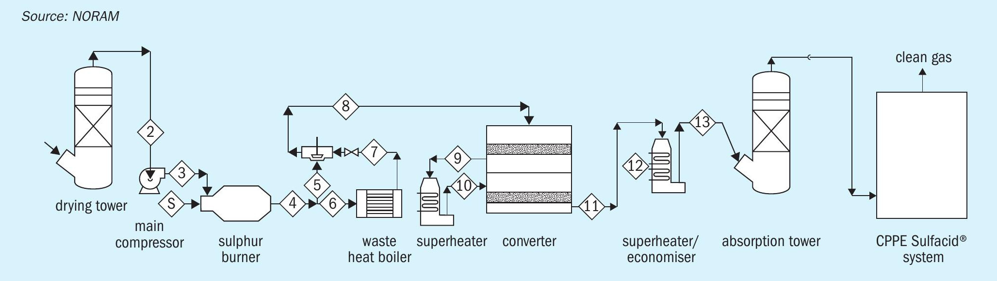
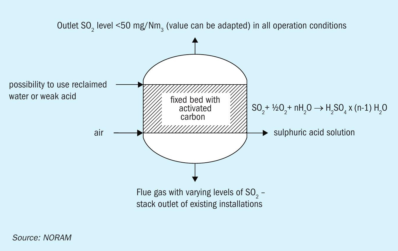
An example of a HSAP plant for sulphur-burning applications is shown in Figure 1. Ambient air is fed to the drying tower to remove moisture. Using the main plant blower, dry process gas is then fed into the sulphur-burner to produce hot SO2 gas. Excess heat is removed via the steam system to generate steam and/or power. A catalytic converter with inter-bed cooling converts SO2 gas into SO3 . This is then absorbed in the absorption tower and finally processed by the Sulfacid® system to produce diluted acid (Figure 2).
In the Sulfacid® system, raw gas is treated as it flows through a fixed bed of activated carbon catalyst inside the reactor. Wet catalysis converts SO2 into sulphuric acid at high efficiency in the presence of oxygen and water. The resulting water-saturated clean gas is discharged to atmosphere via a stack. Water is sprayed over the catalyst intermittently to wash out sulphuric acid collected in pores and on the surface. The clear industrial-grade sulphuric acid obtained flows into a buffer tank.
HSAP – benefits, features and advantages
HSAP is notable for the following key features and benefits:
- Plant design can be adjusted to meet tight emission standards
- The system can tolerate process fluctuations while maintaining low emissions
- No gas re-heat is required – resulting in higher energy recovery from the process gas
- The gas system’s lower pressure drop can be realised as a blower power saving or by increasing capacity l No scrubbing chemicals are required
- The Sulfacid® system is catalytic and does not consume chemicals
- The activated carbon catalyst has a long operational life
- No by-products are produced
- The dilute acid product from the Sulfacid® system is fully-utilised in the contact plant as dilution feed.
Project implementation
HSAP is offered by CPPE-NORAM as a single integrated system. The two companies are able to provide the complete HSAP plant, make all the necessary modifications to the contact plant, and offer a single guarantee for the complete hybrid system.
HSAP can be applied to new plants or retrofitted to those currently operating. It achieves lower SO2 emissions than double absorption systems and can match the performance of other off-gas treatment options. HSAP has very low operating costs, low maintenance requirements and is easy to operate. Minimal operator training is required and the technology and equipment are well known to plant engineers and operators.
The plant can also be designed to meet the requirements of future emissions regulations. Additional Sulfacid® activated carbon catalyst can be added to the equipment, if further emissions reductions prove necessary after installation, without major cost impacts or down time.
Additionally, the system’s ability to cope with fluctuations in SO2 concentration and flow offers operational and environmental benefits. HSAP is less sensitive to fluctuations in SO2 load that occur during process upsets because activated carbon in the Sulfacid® process acts as an absorption ‘sink’. This allows HSAP to reduce start-up emissions, achieve faster start-up times and accept a wider SO2 concentration range during operation – without any impact on plant emissions.
KVT Process Technology (KVT)
KVT Process Technology (KVT) has upgraded its wet sulphuric acid technology to improve plant efficiency in a wide range of settings. Indeed, the company’s OXYSULF process sets a new benchmark in the desulphurisation of waste gases. This energy-efficient, zero waste process achieves exceptionally high sulphuric acid concentrations and sulphur recovery rates.
KVT is an experienced, long-standing provider of environmental technologies. The company is a particularly well known as a supplier of turnkey off-gas treatment plants worldwide.
KVT’s technologies use thermal and/or catalytic oxidation to convert sulphur-containing compounds in waste gases (H2 S, CS2 , COS or SO2 ) into SO3 and finally to sulphuric acid. While the recovery of concentrated sulphuric acid from waste gases or waste acid may be the main objective, KVT always ensures that emissions standards are complied with.
KVT’s OXYSULF technology
OXYSULF, a new technology from KVT, is designed to reduce both investment costs and operating costs (Sulphur 383, p42). It represents a further development of the SULFOX technology originally introduced by KVT in the 1990s.
OXYSULF produces sulphuric acid from the desulphurisation of waste gases. It enables plant operators to eliminate sulphur emissions while at the same time boosting plant economics. The technology is being continuously improved and modified – in response to the changing requirements of KVT’s customers and the demands of environmental regulators.
The experience gained by KVT in sulphuric acid plant design over three decades has led to many improvements being incorporated into the OXYSULF process, including:
- A new reactor design
- A new tail gas reactor concept
- A catalyst that delivers improved sulphuric acid concentration
- A higher sulphur separation rate with no waste stream (pure H2 SO4 instead of gypsum)
- A controlled and safe emissions rate
- Improved reliability l Better economics and sustainability.
OXYSULF’s wide application range
The OXYSULF process can be applied in many different applications:
- Conventional sulphur-burning acid plants (S)
- Treatment of sour gas (H2 S)
- Metallurgical industry (SO2 off-gas)
- Alkylation units in petroleum refineries (H2 SO4 regeneration)
- Viscose fibre industry (H2 S, CS2 )
- Chemical industry, coal gasification, natural gas processing and refinery acid gas treatment (H2 S, CS2 , COS).
Due to the wide range of applications, KVT has defined four types of OXYSULF process. These offer each industry a specific solution:
- OXY NK for lean H2 S, CS2 (e.g. viscose off-gas) and lean SO2 (e.g. furnace flue gas)
- OXY HK for rich H2 S (e.g. refineries, high heat release favours steam generation)
- OXY MET for ‘dirty’ SO2 (e.g. metallurgical, gas cleaning necessary)
- OXY SAR for spent acid and sulphate regeneration (e.g. various petrochemical industries).
KVT has delivered two OXYSULF references to date, one in the metallurgical industry and one in the viscose industry.
The OXYSULF process
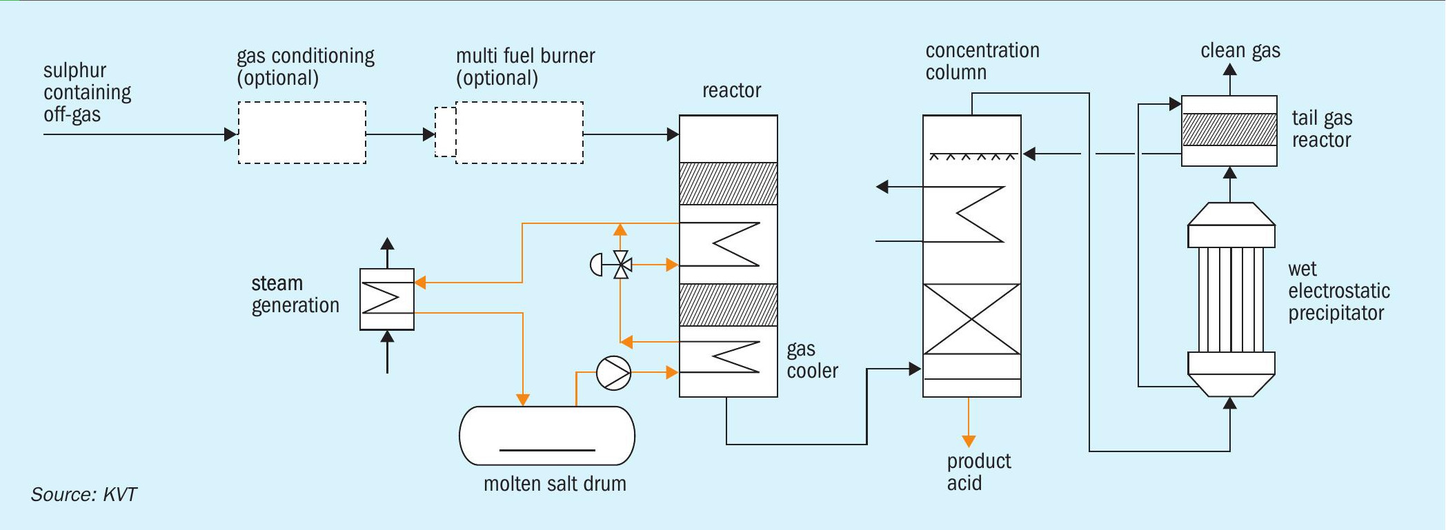
The OXYSULF process is shown in Figure 3. The off-gas gas is firstly pre-treated by passing through a gas conditioning system. This can employ a pre-filter, a scrubber, a Dry-Fil hot gas filter or a preheater, depending on the application. Pre-treatment is followed by catalytic oxidation alone, or by a combination of thermal and catalytic oxidation, according to the concentration of sulphur compounds present. In both cases, the gas is passed over a multi-bed catalyst reactor and then passed onwards to a concentration column and a final tail-gas treatment stage.
Catalytic oxidation is an exothermic process which takes place at temperatures between 200-500°C. The raw gas is initially preheated to achieve the maximum conversion rate of SO2 into H2 SO4 via a series of exothermic reactions. The energy from these reactions can be captured efficiently by a heat recovery system and used for lucrative steam production.
Gas emerging from the concentration column still contains sulphuric acid aerosols. These are removed (to <5 mg/Nm3 ) by a wet electrostatic precipitator (WESP). Precipitated acid is collected in the sump of the WESP and routed to the top of the concentration column to be recovered as highly concentrated acid. Adding a tail-gas reactor can achieve a H2 SO4 concentration of 98 percent and a sulphur recovery rate of 99.9 percent. A tail-gas reactor also ensures the lowest possible SO2 emissions in the clean gas (<50 mg/Nm3 ).
OXYSULF – key advantages
KVT’s OXYSULF design improves plant reliability by including a special reactor sump lining and glass tube heat exchangers, as these items are typically prone to corrosion.
OXYSULF’s novel design also incorporates new materials and alternative technologies such as the molten salt heat exchanging system. This enables the plant to be operated at high temperatures and pressures.
OXYSULF delivers excellent energy recoveries and sulphur yields. The technology is flexible too, being able to handle various gases and hydrocarbons, and is also well suited to refurbishment or expansion projects.
The concentration column is the core element of the entire OXY-SULF process. Leakages and inefficient cooling are avoided, thanks to its improved design, and the highest availability can also be ensured.
Exceptionally long lifetime and operation flexibility is guaranteed due to the use of the highest quality vanadium catalysts and KVT’s specially designed platinum catalyst.
Being a zero waste process, there are no costs for waste management either. The only plant outputs are concentrated sulphuric acid, steam and cleaned gas. The lowest emissions limits can also be met without the need for consumables, thanks to the WESP and the tail-gas reactor.
Sulphuric acid tower design
Sulphuric acid towers are instrumental for the successful operation of sulphuric acid plants (sulphur-burning, metallurgical and acid regeneration types) as well as some gas-cleaning and SO2 plants. The design of sulphuric acid towers requires an understanding of:
- Mass transfer
- Hydraulics
- Packing performance
- Mist formation and removal
- Mechanical design
- Bricking design
- Corrosion
- Materials engineering
- Practical engineering and experience.
Sulphuric acid towers have traditionally been constructed of robust brick-lined steel, providing worry-free operation over a wide range of acid temperatures and acid concentrations, as well as excellent longevity, typically lasting 30+ years. Alloy metal towers have also become popular in recent times
Both bricked and alloy towers have their own distinct benefits and limitations. Alloy towers are lighter and have a quicker installation time, for example, factors that are often critical in plant retrofits. But they also require tighter acid concentration control than brick-lined towers. The latter are capable of withstanding a wider range of acid concentrations should a process upset occur.
NORAM Engineering has capabilities in the design, construction and installation of sulphuric acid towers of all sizes, for multiple applications, and supplies both brick-lined steel and alloy towers (Sulphur 382, p32). Both types can be designed to provide many decades of reliable and trouble-free operation. NORAM’s brick-lined towers include state-ofthe-art bricking, with innovative stable dished bottoms, self-supporting dome packing support, and internal or external water dilution.
The mechanical design limit for NORAM brick-lined towers is 10 metres diameter, which is typical for a 5,000 t/d capacity acid tower. Towers are limited to this diameter by the dome’s mechanical strength. To stay within that diameter limit, larger capacity plants with brick-lined towers either require a different type of packing support, or need two towers operating in parallel. Alternatively, a larger diameter alloy tower could be implemented.
NORAM’s alloy towers are fabricated in high-silicon stainless steel (NORAM SX™ , UNS 23615). There are no mechanical limits to the diameter of the towers made of NORAM SX using a metallic support grid made of the same material. This type of tower can be designed for plants larger than 5,000 t/d with diameters in excess of 10 metres.
Optimising acid tower design
The diameter of an acid tower depends on factors such as:
- Gas flow
- Liquid flow
- Packing type
- Target pressure drop
- Need for the tower to fit the existing footprint
- Potential for future expansion.
Acid towers require packing to achieve intimate contact between gas and liquid. The required packing height depends on the mass transfer rate and the absorption efficiency required.
Koch Knight report that, compared to the previous generation, some newer sulphuric acid plants with wider diameter towers have experienced an increase in failures. The coefficient of thermal expansion plays a greater role in these larger diameter towers, affecting their reliability – this applies to to both brick-lined and alloy towers. (Sulphur 382 p32).
Acid brick lining systems may provide pathways which acid can flow along due to partial porosity, imperfections or via mortar joints. These potential pathways can be sealed by protecting the steel shell with a membrane prior to installing the acid brick lining.
In the past, the preferred membrane material was a trowelled-on acid-resistant mastic. This performed well on smaller towers, lasting for years with little or no maintenance. The major issue with trowelled-on mastic, however, is that it solidifies over time or when it comes into contact with sulphuric acid. Once solidified, and under the stress and compression of brick/shell movement, the mastic will eventually crack or abrade due to its lack of elasticity. In addition, the thickness of the mastic is difficult to control – which can result in a thinner membrane than desired.
Koch Knight’s Pyroflex® acid resistant sheet lining is an alternative membrane option which meets the need for a corrosion barrier and offers a mechanical means of managing gaps between the acid brick lining and the steel shell.
Pyroflex® sheet lining has several valuable properties. Its insulation properties lower the shell temperature while increasing the brick lining temperature. The thermal expansion of the Pyroflex® and its compressibility also increases stress in the lining. Because of this, the sheet lining pushes the brick lining away from the shell, as Pyroflex® shows some ductility at tower operating temperatures.
Reducing tower size through packing selection
Reducing the diameter of sulphuric acid towers is desirable as it has two benefits: It reduces both capital cost while also improving the performance and reliability of the lining system.
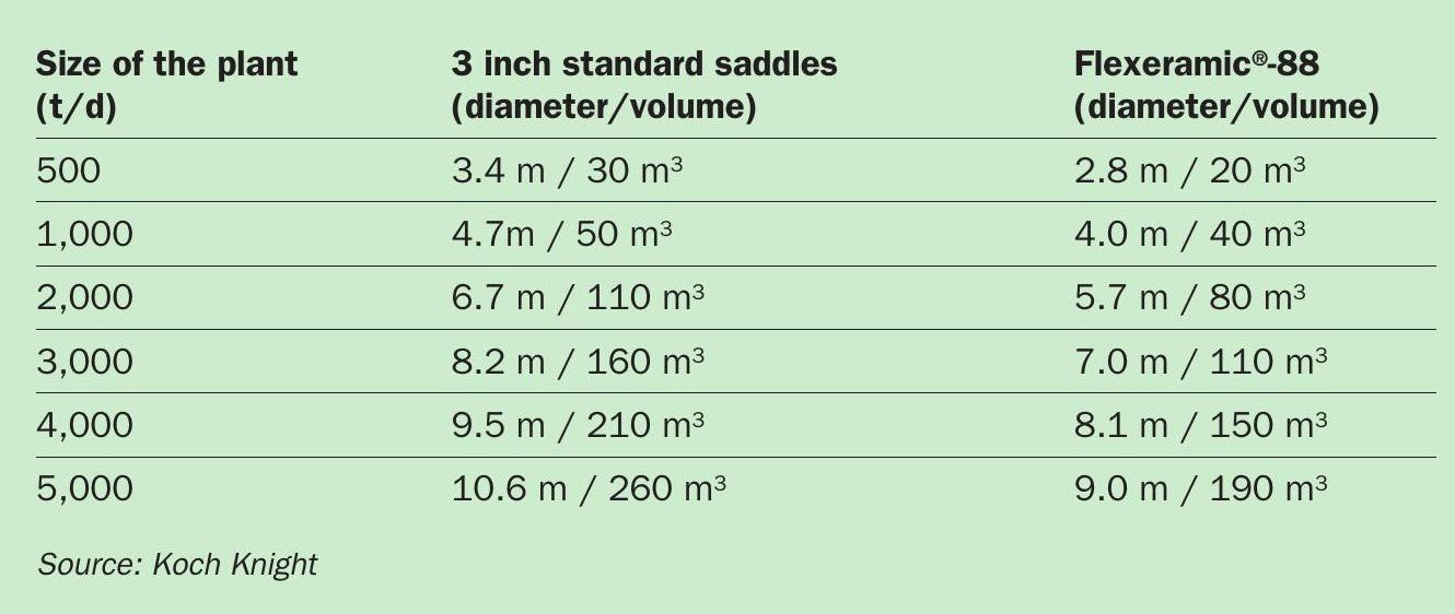
The diameter of acid towers can be reduced, for a given plant capacity, by replacing random packing with structured packing. In a new plant, savings of up to 15 percent of the total tower cost can potentially be achieved, for example, by replacing standard three-inch (75 mm) saddle with structured packing, as this enables a significant reduction in tower diameter for the same plant size. This is illustrated by Table 1 which shows the reduction in tower diameter possible when substituting standard saddle with Koch Knight’s Flexeramic88 ® structured ceramic packing.
In summary, when debottlenecking larger plants, Koch Knight recommends designing these with standard saddles in mind for packing, while using Pyroflex® acid resistant sheet lining to avoid additional stresses. Alternatively, the diameter of the plant’s acid tower – and the power consumption of the blower – can be reduced by adopting structured packing such as Flexeramic88. ® Either option is advantageous for sulphuric acid towers, in terms of both cost and performance.