Nitrogen+Syngas 368 Nov-Dec 2020
30 November 2020
New concepts for ammonia plant revamps
AMMONIA PLANT REVAMPING
New concepts for ammonia plant revamps
thyssenkrupp Industrial Solutions discusses a revamping concept to reduce CO2 emissions by replacing some of the hydrogen in the front end of the ammonia plant with green hydrogen, KBR and Casale report on revamp options to increase the capacity of vintage ammonia plants in the former Soviet Union, Johnson Matthey presents a novel integrated ammonia flowsheet for the production of ammonia, methanol, urea and UFC and Arvos | Schmidtsche Schack discusses the benefits of a new process gas boiler.
THYSSENKRUPP INDUSTRIAL SOLUTIONS
Ammonia plant revamping with green hydrogen
Concepts for green ammonia plants have been presented, where “green” means that ammonia is produced from hydrogen which originates from electrolysis of water, using electricity generated from renewable sources1,2 . Such ammonia would be produced with no or much lower CO2 emissions, compared to existing schemes based on hydrocarbons, e.g. natural gas.
Green hydrogen from an electrolysis unit can also be fed to an existing ammonia plant in order to lower its CO2 emission by combining it with hydrogen from the conventional ammonia plant front end (synthesis gas generation). Plant modifications using green hydrogen can be anything between the two extreme cases of:
- replacement of hydrogen from the plant front end by electrolytic hydrogen at unchanged ammonia production, or
- addition of hydrogen to increase the ammonia production (possible only if the ammonia synthesis unit is not the bottleneck of the plant).
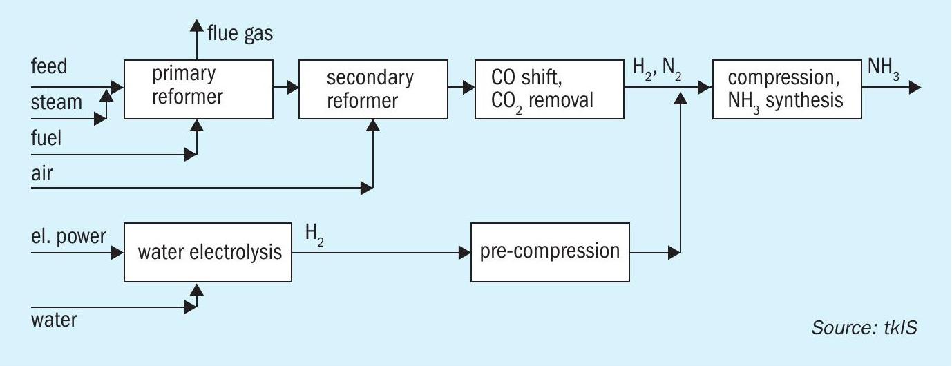
In this case study, the impact on an existing plant is described, when 10% of the hydrogen fed to the synthesis is replaced by hydrogen from an external (carbon-free) source as shown in Fig. 1. The main focus is on how much the CO2 emission can be reduced, whether there are any obstacles for such a modification and how they can be avoided.
Impact of modifications on process units
The reference case for the simulation is an actual uhde® ammonia plant but the study results are equally valid for any ammonia plant based on primary and secondary reforming with stoichiometric process air and with heat recovery for HP steam generation. Electrolysis data are also taken from the uhde® / thyssenkrupp Industrial Solutions alkaline water electrolysis (AWE) process.
It is obvious that the feed gas consumption of the reformer will also decrease by about 10% but there remains a number of questions to be answered:
- What is the change in reformer fuel demand?
- What is the change in steam export?
- Will the operating parameters remain in the limits of design?
- Finally, and referring back to the purpose of the change, what is the reduction of the CO2 emission and operating cost of the plant?
Generally, the modification takes load from the plant front end and thus one might not at first glance expect any problem to arise. The addition of hydrogen at the end of the front end has an impact especially on the reforming unit of the ammonia plant. Process and performance parameters are summarised in Tables 1 and 2.
While the amount of hydrogen from the front end is being reduced, the nitrogen demand has to remain approximately the same because it is dictated by its content in the ammonia produced. This means the natural gas feed and process steam to the reformer are lower than in the reference case, while the air to the secondary reformer is kept unchanged. The front end has therefore to produce a synthesis gas with a H/N ratio of less than the stoichiometric number of 3.
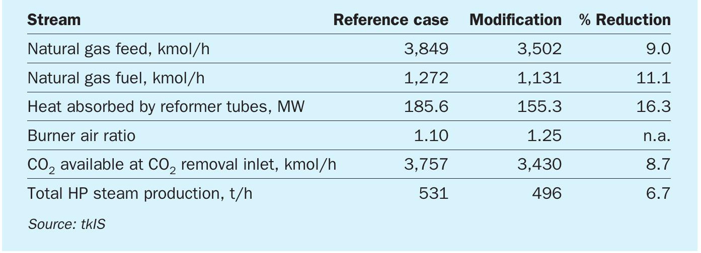
Since the air feed to the secondary reformer is fixed, but its feed stream is lowered, the energy available in the secondary reformer is sufficient to sustain more reforming reaction and therefore allows for a higher inlet CH4 concentration. Consequently, the heat pick-up of the primary reformer tubes is not only lowered by 10% due to lower flow, but additionally by lower CH4 splitting and an 18°C lower outlet temperature. Consequently, the primary reformer is seeing a more than proportional reduction in absorbed heat by not only 10% but 16%.
This shift of the reforming duty from the primary to the secondary reformer leads to a higher temperature rise between the inlet and outlet of the secondary reformer which in the simulated example amounts to 180 K instead of 168 K in the reference case. Luckily, the effect of the lower inlet temperature is the dominating one so the outlet temperature is not higher than normal and thus stays within the design limit.
In the convection bank of the primary reformer another challenge arises because there is less flue gas stream but the rate of the process air stream to be preheated has not changed. Therefore, without any adjustment not enough heat would be available. In the simulation it is postulated that all preheating temperatures shall be maintained as before. In order to achieve that, the air ratio of the combustion is being increased, from 1.10 to 1.25. The air and flue gas flow rates remain within the design limits of the blowers. Alternatively, one could allow for a lower feed/steam preheating temperature in order to lower the duty in the convection bank. Since the primary reformer is operated at lower throughput there is enough margin available to increase the portion of preheating duty in the reformer tubes.
The heat available in the front end for HP steam generation decreases while the conditions in the synthesis section and its HP steam generation remain mostly unchanged. Therefore, the decline in steam generation is less than 10% (Table 1).
A critical consequence of this is the change in process temperature between the waste heat exchanger and superheater downstream of the secondary reformer. The modification results in a rise in temperature, which must be limited in order to avoid the risk of metal dusting. In the example presented here, the temperature goes up by 12°C only and remains below the design temperature. This should be checked in each project case by case.
Downstream of the reforming unit, the situation is less critical. Due to the lower overall gas flow, catalyst volumes in the HT and LT shift are more than sufficient and the outlet CO shift concentration drops. This leads to a lower temperature rise in the methanator, but still sufficient to maintain the reaction, and to the very welcome fact that there are less inserts in the syngas to the synthesis section.
In the CO2 removal unit, the overall gas flow and CO2 to be separated are about 10% below the reference process so no performance problems are expected. The only issue may be the total amount of CO2 if in the reference case it is all being consumed by a downstream plant. In case of no or little CO2 usage, the reduced amount of CO2 venting leads to the desired effect of producing ammonia with a lower CO2 footprint.
Overall performance
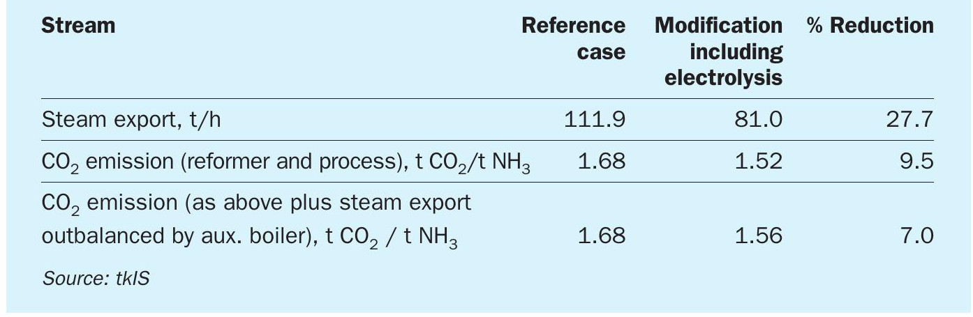
The overall plant performance parameters of the reference configuration and the modification are summarised in Table 2.
There is a significant drop of more than 27% in the steam export from the ammonia plant. This is caused by nearly unchanged operation of many consumers (e.g. refrigeration, process air and syngas compressor turbines) despite lower steam production from waste heat (see above).
For a newly built plant the steam system can be designed around this situation, but for an existing plant the owner has to decide how to handle that. In the worst case, the reduced steam export in the modified operating case will lead to a steam deficit in another unit (e.g. a urea plant) which has to be met by higher production in the auxiliary boiler. However, there may also be cases where the lower steam export can be accepted if its consumer can be replaced by one using an alternative form of energy, like electric power.
The 10% addition of hydrogen from a non-fossil source does not increase the plant CO2 emission. The total CO2 emission, consisting only of reformer stack and CO2 vent, is reduced by about 10% (absolute and per tonne of ammonia). In case the lower steam export has to be replaced by a gas fired auxiliary boiler, and its CO2 emission is included in the comparison (which seems fair), the reduction is only 7%.
A change from natural gas to electricity is not only made for economic reasons. Putting together the ammonia production cost resulting from natural gas and electricity (including the electrolysis, which is the biggest power consumer) shows that the overall production cost is the same for the reference case and modification at a gas cost of $5/million Btu (LHV) and $15/ MWh for electricity.
The electrolysis option becomes more attractive when some kind of tax or allowance for CO2 emission has to be considered. Of course, this increases the production cost for both cases greatly, but, for example, at an emission cost of $30/t CO2 , the overall cost of the modification with electrolytic hydrogen from “green” power is approximately $5/t NH3 lower.
Options for process control
In the conventional plant, the H2 to N2 ratio adjustment is made by regulating the feed flows of natural gas and process air, typically keeping the natural gas constant and matching the process air so that the H2 / N2 ratio at the feed to the synthesis loop is close to the stoichiometric ratio of 3.
In the modified system, with the external feed a third variable comes into play. One scenario is that the external H2 fluctuates in the same way as the available electricity from a renewable source, in which case the ammonia plant will have to deal with and balance out greater fluctuations than usual. Instant reaction is not always required because the loop itself acts as a buffer and small changes in the ratio will result in only a slightly lower conversion.
In the other scenario, if electricity is available continuously without fluctuations, this is perfectly suited for ratio control since the load of the electrolyser and the hydrogen supply can be adjusted within seconds, being a system with less inertia than the ammonia plant front end.
Other benefits
The external H2 stream or a part of it can also be added to the process in ways besides that shown in Fig. 1. One option is to use this H2 as a hydrogenation stream for the desulphurisation, thus avoiding the usual H2 recycle over the front end. Another option is to compress the H2 to synthesis pressure using a dedicated H2 compressor and combining the streams there. This would save steam consumption of the syngas compressor train and might help with the shortfall of steam export mentioned above.
Summary
Summarising the above, there are a few points to observe when replacing part of the hydrogen from the front end by an external source, especially the following:
- outlet temperature secondary reformer;
- energy balance of convection bank;
- gas temperature between reformed gas waste heat boiler and superheater;
- availability of CO2 for downstream products;
- steam export;
- system control if H2 feed is fluctuating.
References
KBR
Revamp of vintage ammonia plants using KRES™ technology
KBR’s experience in the design of ammonia plants dates back to the first plants commissioned in 1944. Since then, KBR ammonia process technology has undergone a number of significant innovations and improvements, which have enabled the owners of KBR-designed ammonia plants to obtain consistently safe, reliable and cost-effective operation. KBR has licensed, engineered or constructed 244 ammonia plants worldwide making it the world’s leading ammonia technology licensor.
KBR’s track record in ammonia plant revamping includes more than 100 projects since 1995 and ranges from small to large increase in production capacity and reduction of energy consumption. In particular, KBR Reforming Exchanger System (KRES™ ) offers the potential for increasing the capacity of the front-end of existing plants by up to 30%, by using high temperature process waste heat exiting the secondary reformer (or auto-thermal reformer) to reform additional flow of natural gas.
This article highlights how the application of KRES™ technology to vintage ammonia plants, originally designed for 1,360-1,420 t/d, can successfully boost their capacity to 2,100 t/d and above as well as reduce their energy consumption.
Vintage TEC and GIAP ammonia plants
In the period from 1973 to 1988, 45 TEC and GIAP ammonia plants were built in the Soviet Union. The design of those plants was based on M.W. Kellogg technology (now KBR) or similar and had the nameplate capacity of 1,360 and 1,420 t/d of ammonia. The original design varied slightly for TEC and GIAP plants but generally included the following sections:
- hydrodesulphurisation;
- primary and secondary reforming with 2+1 downstream waste heat boilers (WHB);
- high temperature and low temperature shifts converters (HTS and LTS);
- CO2 removal section, using potassium carbonate solution (Benfield) for TEC and amine solution for GIAP;
- ammonia synthesis;
- refrigeration, by way of ammonia compressor for TEC and absorption chilling units (ACU) for GIAP.
Over the years, almost all those plants were revamped to bring their capacity to 1,500-1,800 t/d. The modifications typically included:
- revamping main machinery;
- modifying primary reformer: radiant section re-harped, additional MF coil and process air coil, new feed preheat coils;
- halting the fired heater;
- Installing additional parallel LTS converter (TEC);
- upgrading the activator of the Benfield unit (TEC), replacing MEA solution with aMDEA (GIAP);
- modifying ammonia converter basket;
- installing hydrogen recovery unit;
- adding air-cooled heat exchangers and condensers.
Most of the revamps were carried out by replacing the existing equipment with bigger units using the same process design. Only in rare exceptions were licensors involved and new technology solutions implemented. The maximum capacity achieved through implementing such a modification is about 1,800 t/d, which reflects the limit of the main process equipment. As practice shows, any further increase in capacity without implementing innovative technology solutions requires much higher capital investment per additional tonne of product, increases the specific energy consumption and reduces the lifetime and reliability of operation of the plant. This is a problem faced by the owners of ammonia plants built all over the world in the 1970s and 1980s.
The main bottlenecks for further capacity increase are generally the rotating equipment, reforming capacity, performance of reformer WHB, CO2 removal section and ammonia synthesis capacity.
KBR, as licensor of more than half of all built and operated ammonia plants, has been involved in a large number of revamping projects all over the world, from small to large size. In approaching any new projects, KBR applies the lessons learnt from over 100 revamping projects as well as from the 244 grassroot plants licensed and designed.
By applying innovative technology solutions, KBR has demonstrated that it is possible to increase the capacity of vintage TEC and GIAP ammonia plants further to reach 2,100 t/d of ammonia and more, while improving the energy consumption to match the performances of state-of-art grassroots modern plants.
Revamping project challenges
Revamping existing vintage plants has distinct challenges, not only during project execution stages but also over the entire plant lifecycle. Among other factors, special attention is required for the following:
- performance of the revamped plant on a long term basis;
- ensuring high level of reliability of the plant after the revamping;
- considering all costs associated with the revamp project;
- optimising the project schedule to avoid any disruption to the operation of the existing plant (e.g. hook-up of new units during normal turnaround period);
- reviewing and supporting project execution during all phases.
KBR not only places high emphasis on providing cost-effective technology solutions for the overall plant, but also offers the support for the entire project life cycle, including detailed engineering design review, construction advisory, commissioning and start-up support. These involve ammonia revamping specialists in all disciplines and ensure successful project execution, achieving the performance as per design.
The revamping of the whole process plant requires highly specialised modelling capability and proven technology that KBR is in a position to offer due to the large number of ammonia plants in operation that KBR has designed and licensed and the large technology portfolio that KBR offers.
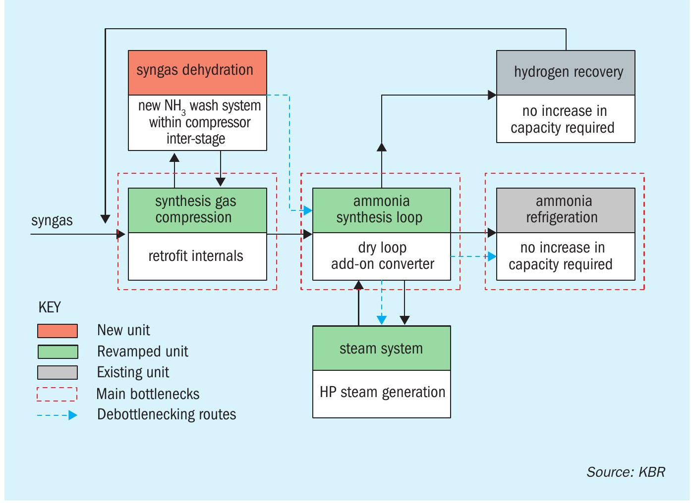
Revamp scheme (2,100+ t/d)
KBR innovative technology solutions to revamp existing TEC or GIAP plants to 2,100 t/d and above include the following main features:
- increase reforming capacity: debottleneck the reforming section by implementing KBR’s proprietary KRES™ technology, along with mechanical knowhow to integrate KRES™ to the existing secondary reformer and waste heat boiler;
- upgrading CO2 removal unit based on modern CO2 Removal Technology (working with third Party) for increased throughput and reduce energy consumption;
- increase synloop capacity by installing a proprietary KBR design add-on converter (or re-using existing spare converter shell with new radial-style catalyst baskets when available) and by optimising synloop operating parameters to minimise modifications required in the synloop and refrigeration system;
- convert to dry loop: existing synthesis loop is converted to a dry loop using liquid ammonia in a new KBR design ammonia wash system (unitised syngas dehydrator);
- machinery upgrades:
– air compressor train: revamp to handle higher capacity and improve efficiency/reduce steam consumption.
– syngas compressor and turbine: revamp to handle higher capacity and improve efficiency/reduce steam consumption.
– refrigeration compressor turbine: revamp to improve efficiency/reduce steam consumption.
These revamp solutions also provide a large reduction in specific energy consumption. KBR also have various technology and revamp solutions to achieve further reductions in energy consumption. These include but are not limited to combustion air preheat, saturator, dry loop with molecular sieve, better heat integration, secondary waste heat recovery.
Key modifications are described in the following sections.
Front end
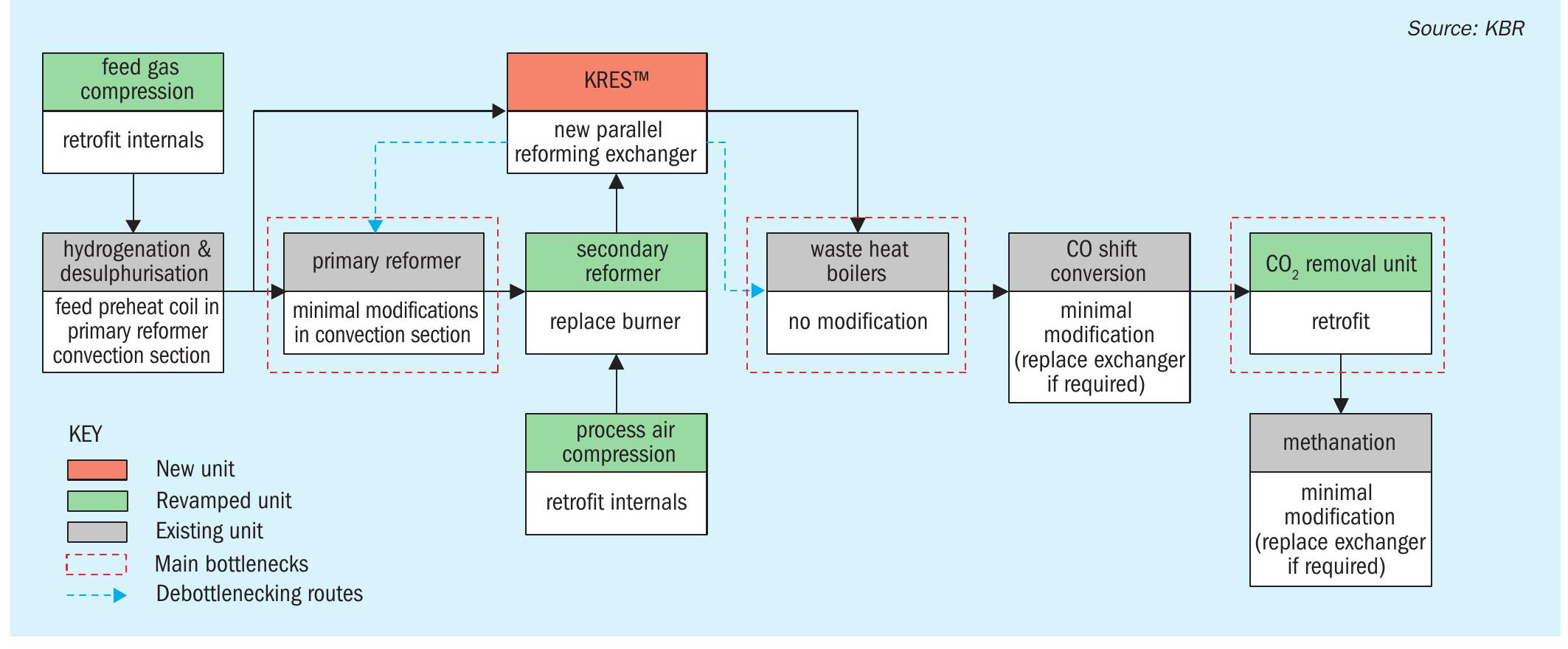
The general revamp scheme of the frontend of the ammonia plant is presented in Fig. 1.
First, the air compressor train and natural gas compressor should be revamped to achieve higher capacity and reduce steam consumption.
Second, the radiant box size and structure of the existing primary reformer furnaces is generally inadequate to accommodate any further revamping aimed at achieving stable and reliable operation above 1,850 t/d ammonia capacity. Extensive modification of the full box, such as adding rows and expanding size of radiant box, involves high cost and very long shutdown period. Therefore, a cost-effective approach for revamping of vintage ammonia plant requires innovative technology solutions in the reforming section.
Third, the original design waste heat boilers need to handle large increase in heat load, suffer more frequent failure, which affect plant reliability.
These key bottlenecks, primary reforming and waste heat boilers, are resolved by the installation of the KBR KRES™ exchanger, which provides the additional reforming duty by using high grade process heat exiting the secondary reformer (or auto-thermal reformer). The details of construction and references of KRES™ are presented in earlier publications1-6.
- avoid major expensive modifications and long shutdown period of reforming furnace area;
- improve thermal efficiency of existing furnace system as convection duty relative to the radiant duty is higher (compared to no KRES™ scenario), thus enhancing ammonia plant energy efficiency and reducing CO2 emissions per tonne ammonia;
- avoid major expensive modification/ replacement of secondary reformer waste heat boilers;
- No change to ID fan as flue gas flow, temperature and fan head is not increased;
- Reduce front-end pressure drop and maximise synthesis compressor suction pressure;
- avoid/minimise changes in HP steam/ BFW system/drum/pump;
- well-proven and reliable technology with 25+ years operational experience in ammonia plants;
- open-ended catalyst tube design which eliminates thermal and mechanical stress – ensuring high reliability;
- easy loading and unloading of catalyst using the same tube bundle saving cost and downtime of replacement.
Due to the increased quantity of process air required for higher ammonia production, the existing secondary reformer generally needs burner replacement.
One of the key challenges is how to physically connect the existing secondary reformer with the KRES™ exchanger and the KRES™ exchanger with the existing waste heat boiler. These connections need to be done via refractory lines (transfer lines). KBR has successfully provided tailored solutions in different types of ammonia plants, both KBR and non-KBR plants, which require different approaches.
For TEC/Kellogg or GIAP plants, KBR has developed an optimal arrangement and routing for the transfer line systems to and from KRES™ , which minimises site work. This was implemented in KBR’s recent revamp in Russia.
The existing reforming waste heat boilers are generally suitable for post-revamp operation due to the decrease of heat duty after installation of KRES™ .
The shift reactors and methanator do not usually require modification. However, internals can be modified to reduce pressure drop.
The CO2 removal system is revamped for increased throughput using the most up-to-date technology available. All existing equipment is re-used after the revamp. Existing column internals typically require modification as well as solution pumps.
Finally, the front-end pressure profile is studied in detail and optimised in order to maintain process gas pressure as high as practically economic.
Back end
The general revamp scheme of the synthesis loop is presented in Fig. 3.
The syngas compressor and driver typically require modification to achieve higher capacity and reduce steam consumption. Usually the compressor internals can be retrofitted.
A new ammonia wash system, (unitised syngas dehydrator), can be installed in the inter-stage of the syngas compressor to dry the make-up gas. The primary purpose of the new ammonia wash system is to remove water from the synthesis gas before it enters the synthesis loop. This allows conversion of the existing “wet” loop into a more energy-efficient “dry” loop. KBR’s ammonia wash system (unitised syngas dehydrator) is a compact design with minimum footprint achieved by stacking upand integrating a vertical wash exchanger on the syngas dehydrator column. Conversion of “wet” loop into “dry” saves power on the syngas circulator by improving conversion per pass in the synthesis loop and reducing circulation flow. This scheme also results in increased energy efficiency due to reduced cooling and heating usage.
The required additional ammonia production is obtained by installing a new add-on ammonia converter, (Fig. 4). The following benefits can be achieved:
- higher per pass ammonia conversion;
- increased condensation of ammonia inside water or air cooler, avoiding changes in refrigeration system (no medication required to refrigeration machine);
- reduced duty on the synthesis gas compressor, enabling cost effective and reliable retrofit of its internals;
- improved energy efficiency of whole plant by saving power on synthesis machine and duty on refrigeration system;
- avoids changes in high pressure synthesis loop equipment and piping by avoiding an increase in circulation flow as well as an increase in velocities and heat duty on most equipment;
- generates additional HP steam in the synthesis loop in a new boiler which provides a flexible steam balance.
The temperature of the flow leaving the ammonia converter is high enough to generate HP or MP steam. HP steam generation offers energy benefit whilst the MP steam generation avoids having a long pipe run for the HP saturated steam.
CASE STUDY Dorogobuzh, JSC (Acron Group)
PJSC Acron is one of the fastest growing fertilizer producers, not only in Russia, but also globally. In 2017, Acron’s management set the ambitious goal to achieve the highest possible capacity on its operating plants with cost-effective investments. The revamping of one of its TEC ammonia plants in Dorogobuzh was selected as a pilot case. KBR technology was selected for the revamping project, offering an opportunity to introduce on the territory of Russia/CIS countries its well proven technologies in the first-of-its-kind project of revamping of TEC /GIAP plants. The project implementation period was also very ambitious, targeting completion by 2019.
The TEC ammonia plant in Dorogobuzh had a nameplate capacity of 1,360 t/d. Over the years the plant’s output was increased to 1,725 t/d.
Upon completion of the revamping project in December 2019, the plant achieved the guaranteed capacity of 2,100 t/d with simultaneous energy savings by 9%. Moreover, the plant reliability was enhanced as demonstrated by uninterrupted operation of the plant since start-up.
The project team included KBR as licensor, basic engineering designer and proprietary equipment supplier, R&DC Acron Engineering (Acron Group) as general designer, Dorogobuzh (Acron Group) as general manager and organiser of construction.
The scope of the revamp included the state-of-art KBR design solutions KRES™ and the cold wall add-on ammonia converter as main design features for modernisation of the reforming and synthesis sections, respectively. Most of fabrication and installation works was performed during normal plant operation and only the tie-in of new equipment was done during a normal plant turnaround within 42 days. Upon stabilisation of performance after start-up the plant achieved all guaranteed figures. n
Refrigeration
The outlet ammonia concentration from the add-on converter is significantly higher than the concentration from the existing converter, thus the additional ammonia made can be condensed against air water cooler. This allows the existing refrigeration compressor to operate at similar refrigeration loads compared to the current operation; hence, no modification is expected.
Steam system
Application of the KRES™ technology reduces the high pressure steam generated in the front-end waste heat boiler. This reduction is compensated by the high pressure steam generated in the synloop boiler, thus balancing the steam system. Modifications affecting the steam system have already been outlined in the previous sections. The main modifications include:
- revamp to improve energy efficiency of major turbine drivers;
- the steam generated from the new loop boiler is connected to the steam superheaters;
- the steam superheat coil can be modified to preheat HP steam to higher temperatures.
Cooling water system
Generally, no change/increase is expected to the cooling water system. However, if the cooling water reserve is available, then additional cooling can be implemented for better efficiency.
Relief and flare system
The revamp of TEC or GIAP plants typically require modernisation of the flare system, reusing the existing stack for the front-end and installation of a separate stack for the back-end.
Preliminary energy saving
Energy saving for the above scheme ranges from 1 to 1.5 Gcal/t (LHV) depending on the extent of modification implemented to reduce the energy consumption. KBR can recommend the most cost-effective approach in a feasibility study.
Conclusions
Revamping of vintage ammonia plants is an attractive way to extend their lifetime and increase profitability. KBR offers cost effective proven technology solutions for ammonia plant revamps to increase the production capacity and enhance energy efficiency. The competitive advantages of KBR technology were successfully demonstrated during implementation of the revamp project for Dorogobuzh JSC (Acron Group). This approach for revamping of TEC and GIAP plan can be efficiently applied to other plants.
References
CASALE SA
Casale revamping of GIAP ammonia plants
GIAP, which stands for “Gosudarstvennogo Instituta Azoti Promishlennosti” or “State Nitrogen Industry Institution”, developed a domestic Russian technology for the production of ammonia, based on the Kellogg process.
The front end of a GIAP plant is very similar to Kellogg plants, the main exception being the CO2 removal section, where columns are designed with special trays in some cases (in AM76/AM80 schemes) equipped with internal coils to provide heat.
Another feature of these plants is the use of absorption coolers instead of cooling cycles based on ammonia compression that is proposed by all other licensors.
GIAP built 37 plants from the early 1960s through the 1980s. The institute left the ammonia plant market just before the collapse of the Soviet Union in the early 1990s. There are currently 25 operating ammonia plants designed according to GIAP technology AM70/AM76 or AM80 in Russia and the former USSR countries.
Casale has developed and patented specific process schemes and technologies for the revamping of these plants, in particular to increase their capacity and make them stable throughout the year. Most of these technologies have already been applied by Casale for the revamping of GIAP ammonia plants.
While the following information discusses the revamping of GIAP plants, most of the concepts and technologies are applicable to any plant type.
Capacity increase — AARP (AXY) section
A problem that is commonly faced when the capacity of GIAP pants is increased, or when the air temperature increases during the summer months, is the cooling limitation of the existing AXY (the Russian acronym of AARP, aqua ammonia refrigeration package).
The lack of AARP cooling capacity often results in a serious bottleneck for plant capacity increase, or reduced plant production during the hot season.
The typical upgrading developed for AARP sections concerns the ammonia condenser (item 903): air cooled condensers are normally replaced with evaporative condensers to improve the AARP distillation section.
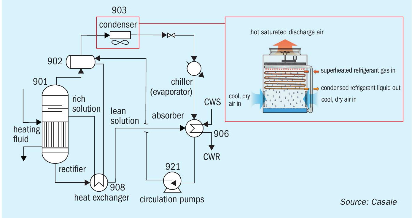
Fig. 1 shows a typical AARP revamping approach.
Thanks to the lower condensation temperature achievable with evaporative condensers, it is possible to decrease the regenerator operating pressure and thus temperature approach in the regenerator reboiler. This results in an increased distilled ammonia flow rate and consequently enhanced AARP cooling capacity.
Unfortunately, if nothing is done to also improve the ammonia absorption (item 906), the improvements can result in modest or even disappointing overall results.
AARP cooling capacity increase is inevitably tied to ammonia vapour absorption: if more liquid ammonia is sent to the process chillers, more ammonia will need to be absorbed.
The ammonia absorption by means of regenerated lean aqua-ammonia solution is in fact as critical as rich solution regeneration: a weak vapour absorption can lead to a pressure and temperature increase in the chillers, which would have a detrimental effect on the process cooling.
Additionally, ammonia absorption is influenced by the operating conditions (temperature and flow rate) of the cooling water.
Casale’s approach is to closely analyse all AARP sections, in order to understand which ones are preventing the system from reaching its design capacity. In particular:
- ammonia condensation (item 903);
- ammonia absorption (item 906);
- rich solution regeneration (items 901, 902, 908).
The most common example is represented by the difficulties in achieving the required AARP performances even after the replacement of item 903. Often, once the limitation in ammonia condensation is removed, the ammonia absorption (item 906) becomes a much more difficult bottleneck to deal with.
Two revamping approaches are known to overcome limitations in the ammonia absorber (item 906):
- The first approach is to provide additional CW exchangers for the existing ammonia absorber (see Fig. 2). The drawback of this approach is the higher cooling water consumption. For this reason it is not always applicable due to limitations on cooling water availability (CW pumps and/ or cooling towers) and it increases plant overall energy consumption.
- The second approach is the Casale cooling module, a new technology developed by Casale for its clients, aimed at reducing the duty requirement in the existing absorber.
Ammonia vapours are routed to a pre-absorption column where they are washed with lean NH3 -H2 O solution coming from the AARP regenerator.
Semi-lean solution from the pre-absorption column bottom is divided into two streams: one stream is cooled at the expense of air and DW evaporation in a dedicated cooling loop, the second stream is sent to the existing absorber to complete absorption of the pre-absorption column overhead.
Since most of the ammonia vapours coming from the process chillers are absorbed in the pre-absorption column, the load on the existing absorber is drastically reduced.
The Casale cooling module can be designed to overcome existing absorber limitations, increasing overall AARP cooling capacity, or even to completely replace item 906 (AARPs with no CW consumption can be designed following this principle).
The Casale cooling module is installed upstream of the existing absorber and will partially condense ammonia vapours at the expense of air. Cooling water can therefore be saved in the existing absorber CW exchangers.
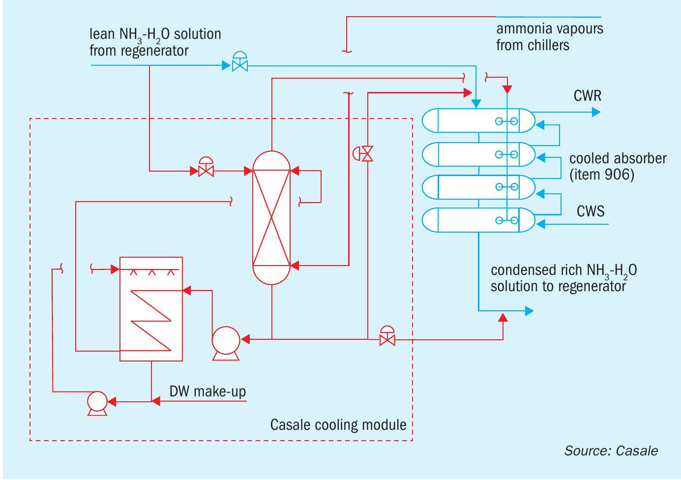
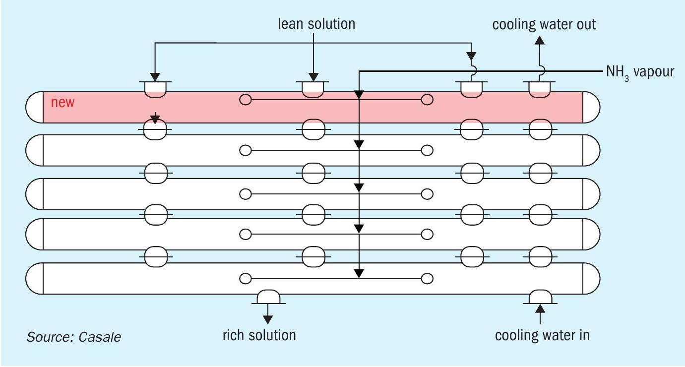
Fig. 3 shows a sketch of the absorber after implementation of the Casale cooling module (for the existing absorber refer to Fig. 2).
In this case, the Casale cooling module is carefully designed in order to minimise the pressure drop and maximise the achievable process benefits.
- AARP ammonia vapour absorption power will be increased, allowing the AARP cooling capacity to be increased with the maximum benefit.
- Cooling water can be saved from existing absorber CW exchangers, creating room on CW pumps and cooling towers for additional users (e.g. compressor inter-stage coolers, new process water coolers, new lithium-bromide units, new AARPs).
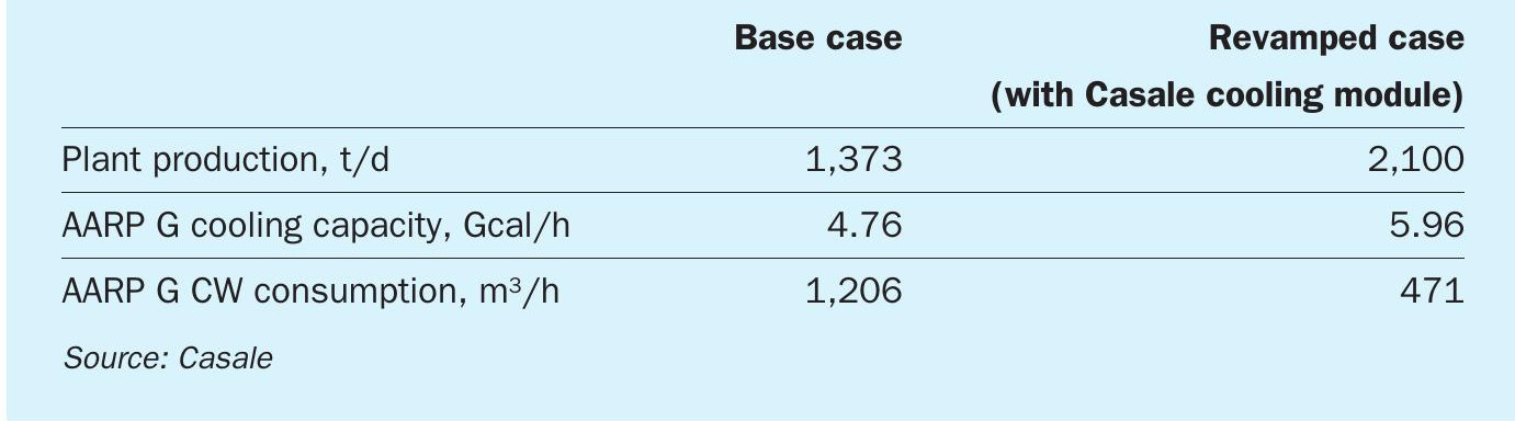
The example in Table 1 shows the expected effect of the Casale cooling module if applied on AARP G (-10°C thermal level) of a reference GIAP AM76 plant.
The client’s request was to both increase plant production and improve overall energy consumption.
As shown in Table 1, AARP cooling capacity has been increased (restoring most of its original design cooling capacity) and, at the same time, cooling water consumption has been reduced by 60% with respect to the base case.
In this example, the cooling water saved in AARP G was used to cover the additional consumption of the compressor’s interstage coolers and new CW exchangers (both necessary for the increased plant capacity).
The Casale cooling module improved the project economics by avoiding the need for an expensive new cooling water circuit (i.e. new additional circulation pumps, new additional cooling towers etc.).
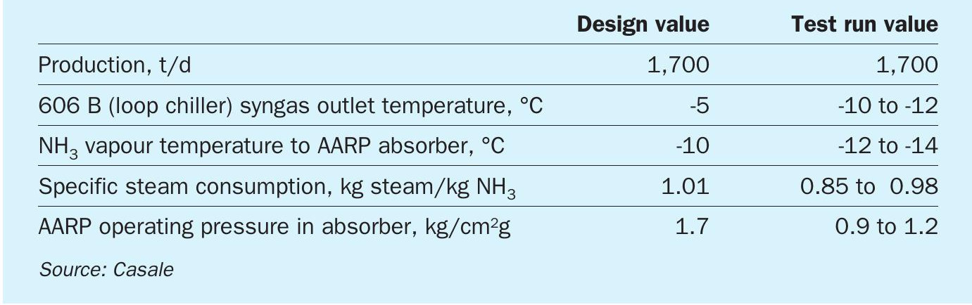
Casale also has experience in the design and supply of new aqua ammonia refrigeration packages. In the revamping of a GIAP plant in 2015, Casale supplied a new unit of 10 Gcal/h cooling capacity at a thermal level of -10°C, the biggest ever installed in Russia. This new unit uses 3.5 kg/cm2 LP steam to drive the refrigeration cycle. Casale engineered the integration of the new unit within the existing ammonia absorption refrigeration system and was responsible for all the project steps, from basic engineering up to delivery. Table 2 shows the performance of the new aqua ammonia refrigeration package.
Besides the classical AARP based on -10°C or +1°C ammonia operating temperatures, Casale has also developed a new version particularly suited for energy saving, summer stabilisation and negligible consumption of utilities.
The new AARP is designed assuming +5°C and +10°C respectively as ammonia operating temperatures, which allows the use of evaporative condensers or dry air coolers instead of shell-and-tube heat exchangers for the absorption phase.
The use of cooling water as cooling medium is therefore not required in the new scheme; additionally, the heating source is very low pressure steam (1-2 barg) or even hot water.
Capacity increase — CO2 removal section
The CO2 removal section is one of the most critical in ammonia plants and it is usually a bottleneck when the capacity is raised above the plant design capacity.
The original design of CO2 absorber is not usually suitable for revamped conditions, since the existing internals must cope with higher process gas and amine solution flow rates.
Casale acquired the license and all know-how of the CO2 removal process developed and owned by Karpov Institute of Physical Chemistry. Hence, Casale is the only company able to revamp original AM70 & 76 CO2 absorbers by applying the original design philosophy.
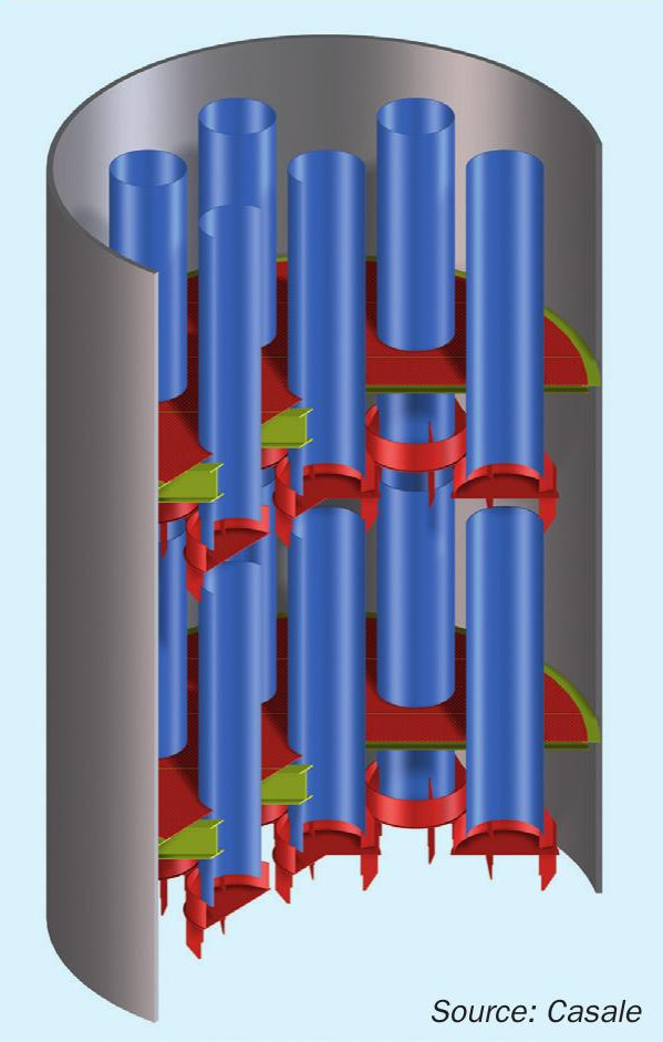
Casale multipipe trays (Fig. 4) can be designed to cope with the new column hydraulics, allowing the low CO2 slip, characteristic of GIAP plants, to be maintained and overcoming the difficulties given by the simple installation of random packing in place of trays.
Replacing existing absorber trays with random packing can undermine the CO2 separation efficiency, leading to an excessive CO2 slip and consequent higher synloop inert content.
Due to their specific design which provides a high contact time between phases, multipipe trays (existing GIAP absorber trays or new Casale multipipe trays) are almost twice as efficient than common trays and random packing and replacing them with a different technology (e.g. commercial trays or random packing) would imply a much higher amine solution circulation rate than Casale multipipe trays to maintain control of CO2 slip.
Unfortunately, such additional flow rate is rarely available due to the physical limitations of lean and semi-lean pumps. Additional pumps can be added, but increase the revamping cost, jeopardising the investment payback time.
The advantages of Casale multipipe trays can be summarised as:
- high efficiency;
- efficiency estimated to be as much as double that of standard sieve trays;
- no wall effects – preferential paths and distribution problems are avoided, unlike random packing absorbers;
- a higher approach to equilibrium is achieved;
- higher active area compared to standard sieve trays, allowing for the design of smaller absorption columns.
Casale has already successfully applied this technology for the revamping of GIAP plants, in particular, absorber tray revamping making these sections suitable for a capacity of at least 2,100 t/d.
Another section strongly limited in case of capacity increase (especially during summer) is CO2 compression in the urea plant.
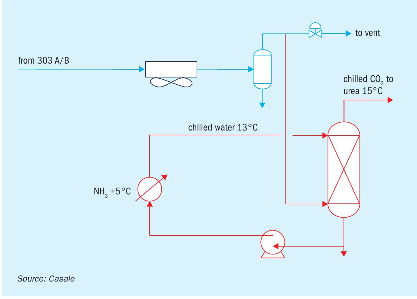
To overcome this, Casale proposes the installation of a CO2 chilling section as shown in Fig. 5 where red identifies new lines/equipment.
After water is separated in item 322, CO2 is diverted to the new chilling column 3001 where it is cooled down to 15°C by circulating chilled water at 13°C.
Thanks to the new CO2 chilling section it is possible to debottleneck the CO2 compressor in the urea plant: volumetric flow at the compressor inlet decreases by about 10-15%, making it possible to reduce the power requirements/costs of a new parallel compressor for a urea capacity increase.
Additionally, due to the lower feed gas temperature, the electrical consumption of the CO2 compressor is reduced (savings: ~350kW @ 1,320 t/d urea and ~435kW @ 1,800 t/d urea).
CO2 delivery pressure at battery limits will not be decreased with respect to base case since the pressure drop of the additional column is very low and can be easily recovered by a small increase of the operating pressure of the strippers 303A/B. The regeneration penalty coming from the slightly higher operating pressure of the CO2 stripper is negligible.
Water is chilled by an additional CO2 water chiller (item 3003) fed by liquid ammonia from AARP A. Such ammonia is evaporated at 4.3 kg/cm2 g so that the evaporating temperature is around 5°C, avoiding any freezing risks.
A CO2 chilling section very similar to the one proposed here was successfully commissioned in two Romanian ammonia plants respectively in 2015 and 2016, and in an ammonia plant located in Saudi Arabia.
Improve CO2 purity
The existing CO2 removal section of the GIAP AM76 plant is usually already equipped with a clean/dirty separation system located in the regenerator top.
However, solution degradation, mechanical issues or other problems may have affected this system/device, and in any case, the clean CO2 flow rate should be maximised.
Such improvement can be accomplished by the internal modification of towers 303A/B, or by means of the installation of a pre-desorption unit. Casale offers both solutions.
Internal separation device
The solution involving the modification of the regenerator top (solution applicable to any regenerator/stripper) foresees the installation of a separation device (Fig. 6), where dirty CO2 is separated from clean CO2 ; proper sealing avoids any mixing between the two streams.
This technology can be applied both to amine and hot potassium based CO2 removal sections. The maximum recovery of clean CO2 is usually about 70-80% of the overall CO2 recovered by the CO2 removal section, the balance is a dirty stream of CO2 .
External vessel solution
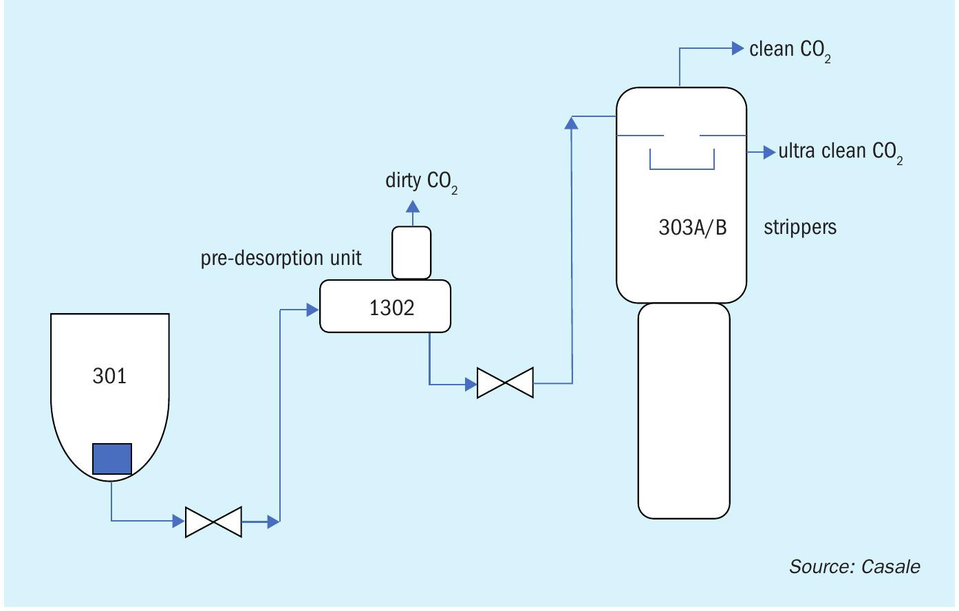
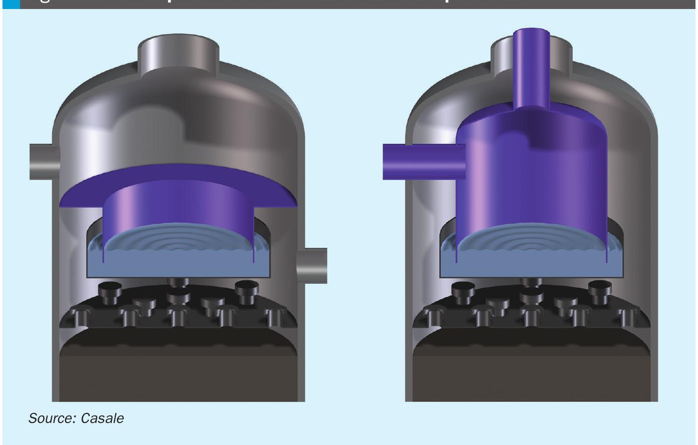
In case of a pre-desorption unit installation, the process flow scheme is modified as follows (see Fig. 7).
The pre-desorption unit is installed between the absorber, item position 301, and the regenerators 303 A/B; the rich amine stream coming from the absorber is de-pressurised and fed to the new pre-desorption unit to separate the released gas from the liquid, a small washing tower is usually provided in case part of the CO2 released needs to be recovered.
The pre-desorption unit is designed with the proper residence time. The pre-desorption unit internals are designed to improve the H2 release (degassing of the amine solution). The CO2 stream released from the pre-desorption unit top contains more than 6-7 mol-% H2 (dirty CO2 stream).
The pre-desorption unit (Fig. 8) is located at a certain height from the ground in order to provide the capability to operate within a certain pressure range and in order to optimise the H2 desorption from the amine solution.
The pre-desorption unit is installed upstream of item 303A/B and is operated ideally up to the range 2.3-2.8 kg/cm2 g, therefore the final elevation of this new equipment is selected in order to allow stable operation at these conditions.
Considering these operating parameters, the regenerators could produce ultra-clean CO2 (that should be enough for the new urea plant) and also a new stream of clean CO2 with less than 500 ppm vol maximum content of H2 (this content could be further reduced by lowering the operating pressure of the pre-desorption unit, or by installation of a solution/solution new exchanger with low pressure drop).
To provide the previous operating conditions, modifications should also be made to the top of item 303A/B; the bottom vortex breaker of item 301 is also typically modified to reduce the entrained H2 in the amine rich solution fed to the pre-desorption unit.
Capacity increase – synthesis loop
The ammonia converter in GIAP plants is normally a bottleneck for capacity increase. The maximum achievable capacity without replacing the original converter or adding a second converter in series or parallel operation is around 1,850-1,900 t/d.
However, thanks to Casale modifications to converter 601 internals and to the availability of the new AmoMax-Casale catalyst, it is possible to achieve a maximum production of 2,000+ t/d without adding new converters to synthesis loop.
Ammonia converters internals modification
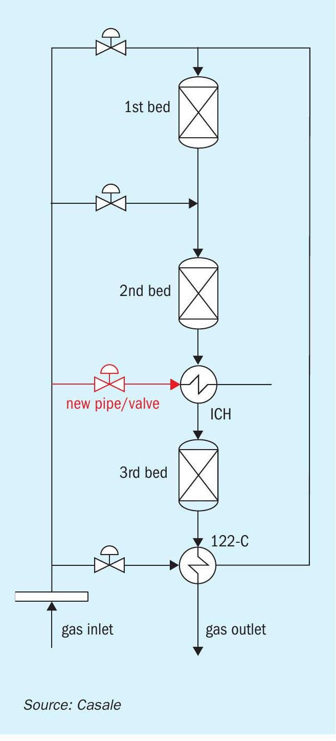
One of the most important modifications to the internals to improve the operation of this converter is the feeding line to the interchanger.
The interchanger located between the second and the third converter is fed from the bottom with a new dedicated line and valve (Fig. 9), reducing the relevant pressure drop and improving the operation efficiency of the revamped ammonia converter. This solution has been applied by Casale in more than a dozen of converters, similar to the GIAP one, in ammonia converters located in China, Saudi Arabia, Trinidad & Tobago, Belgium, Canada and the USA.
The old top interchanger feeding nozzle can be reused to feed the existing quench torus located at the outlet of the first bed (as an additional nozzle parallel to the existing one), reducing the feeding pressure drop for this service and making the converter more reliable and efficient (the second and third bed will be optimised to achieve better performance).
Thanks to all of these modifications the main valve will be less throttled and the synthesis loop will have a lower pressure drop.
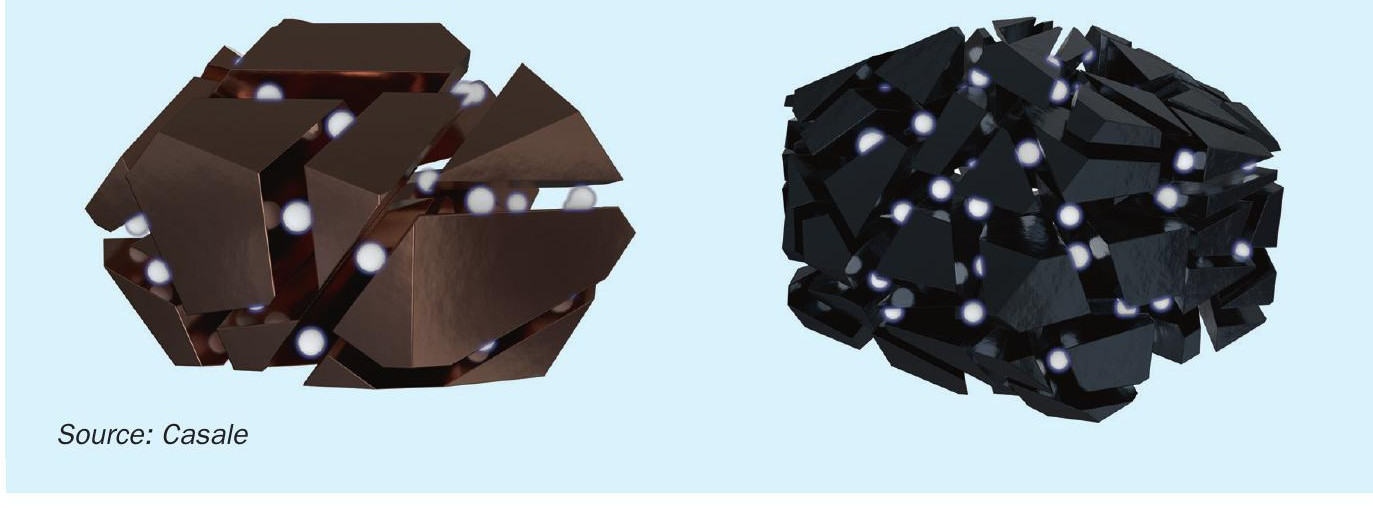
Amomax-Casale
AmoMax-Casale is a new ammonia synthesis catalyst developed by Clariant and Casale particularly for use in Casale ammonia converters.
AmoMax-Casale is an evolution of the well-known, wustite-based catalyst, AmoMax® 10 and represents the latest innovation in ammonia synthesis catalysts. AmoMax-Casale retains the same superior resistance to ageing, poisoning and mechanical strength of AmoMax® 10 but is significantly more active.
Catalyst activity has been evaluated up to 25% higher than the standard iron-based catalyst (wustite or magnetite catalysts).
The superior performances offered by AmoMax-Casale, compared to catalysts offered by competitors, allows a further increase ammonia conversion per pass improving project economics. This feature allows the loop recycle rate and the loop pressure to be reduced and/or the ammonia production to be increased.
AmoMax-Casale catalyst consists mainly of ferrous oxide (wustite) with a tailor-made and optimised set of promoters that stabilise the iron crystallites and increase significantly the surface area of the activated catalyst (see Fig. 10).
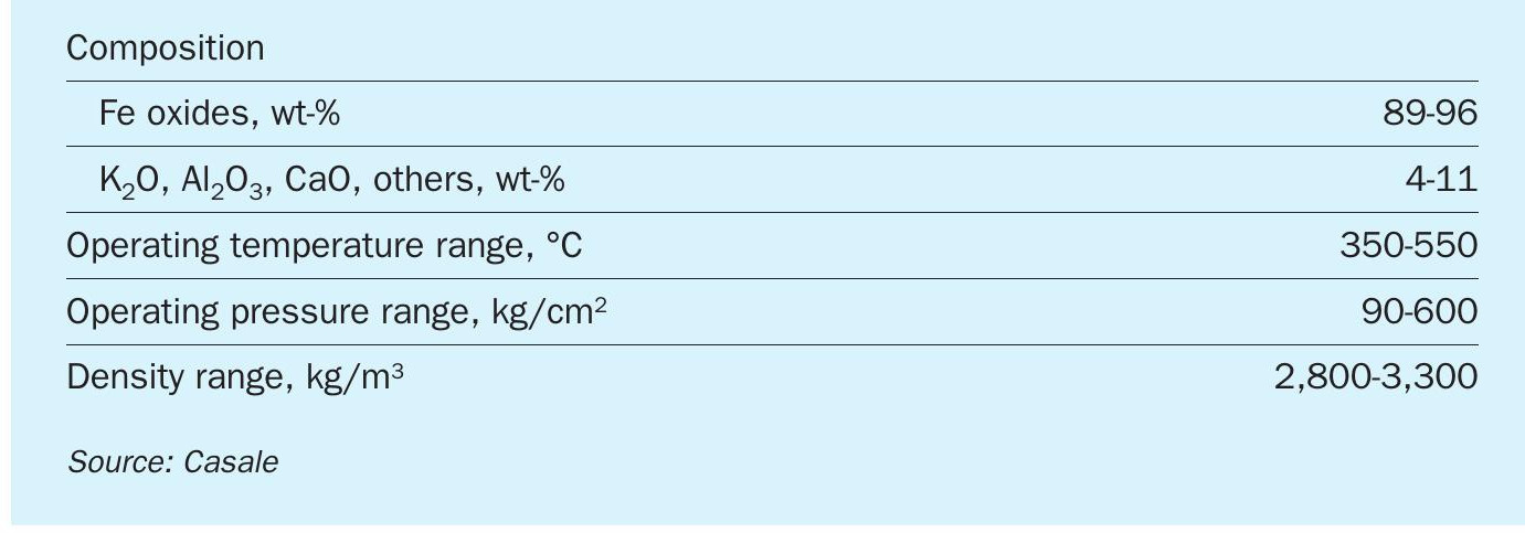
Technical features of AmoMax-Casale are shown in Table 3.
AmoMax-Casale has been successfully applied in a Central American plant very similar to GIAP plants (started-up in December 2019). Amomax-Casale has been installed in the third bed of an existing ammonia converter, providing a superior conversion per pass in the existing synthesis loop.
The converter internals were modified as per the previous description (new interchanger feeding line and valve).
As a result of the Casale converter revamp, the synthesis loop can now run at a much lower pressure than before (about 10 bar lower) and, at the same time, with an inert content much higher (about 50% higher than before), resulting in a tangible energy saving and a plant capacity increase above nameplate capacity.
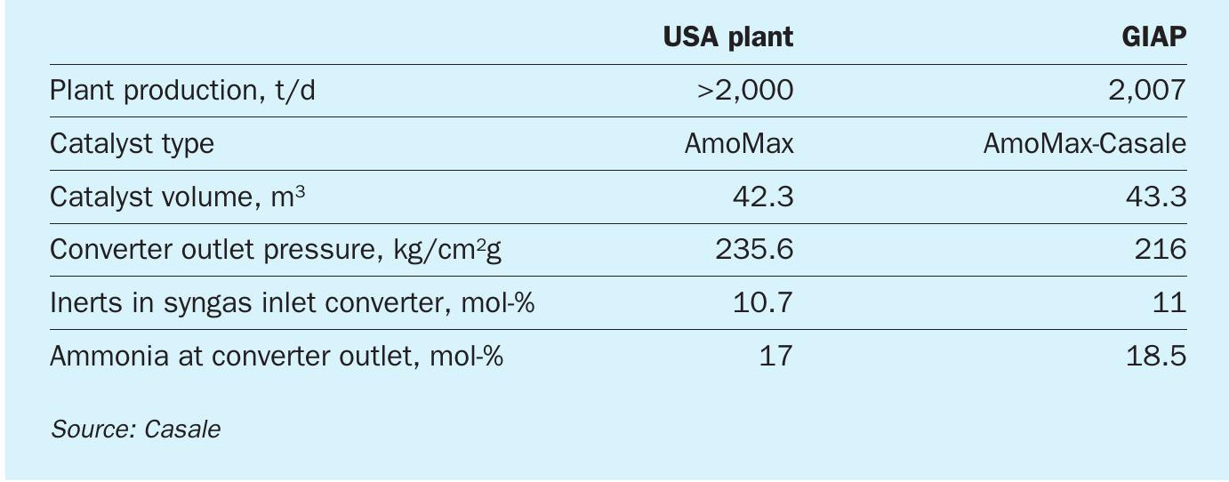
There are also Casale references for operation at 2,000 t/d with a single ammonia converter.
Table 4 summarises the main data related to a plant located in the USA where the operating conditions, the ammonia synthesis converter and the catalyst volume are close to those expected for an existing GIAP reactor.
Summer stabilisation
Ammonia plants in Russia and the former USSR countries are often limited during summer time because of the unfavourable ambient conditions; ambient air temperature can be quite high (>30°C) which impacts the cooling capacity of the air coolers as well as of the cooling water exchangers installed in the ammonia plant.
For GIAP AM76 plants, poorer performance of item 604 in the synthesis loop (air cooler condenser) overloads the ammonia chiller 606 and consequently the relevant AARP-10. Such loss of cooling capacity can reduce plant output by as much as 100-200 t/d during summer.
A simple way to solve the issue is to install a chilled water exchanger or an ammonia chiller (for instance with ammonia +5°C), just downstream of item 604.
Respectively, a chilled water exchanger would require the installation of a lithium/ bromide unit, while an ammonia chiller would require a new AARP. Casale has experience to supply both.
In case additional cooling water is not available (limitation given by existing CW pumps or cooling towers), the installation of a new cooling tower would be required, which is normally quite expensive.
In light of this, Casale has developed a new arrangement focused on the reduction of cooling water used by the plant biggest AARPs (i.e. AARP “A” and AARP “Г”), without impacting (or possibly even improving) their cooling capacity. The new arrangement is possible by the installation of new equipment i.e. the Casale cooling module, described earlier.
Basically, the existing AARP is modified taking into consideration that the ammonia vapours coming from the chiller, once washed/contacted with the lean solution release heat. By accomplishing most of the absorption in the new Casale cooling module it correspondingly reduces the requirement of the other existing absorption equipment (item 906). Eventually the cooling water requirement is hugely reduced, and additionally the cooling water still fed to the absorber (item 906), after heat exchange, is sent back to the existing cooling tower at a temperature 1-3°C lower than the current design making the cooling tower operation more efficient and effective.
A new single Casale cooling module can be provided for both AARPs, allowing plant production to be stabilised during the summer months (i.e. maintaining winter production levels throughout the year).
In case of lack of cooling water an effective alternative would be to also install a brand new Casale AARP equipped with absorber and condenser designed with dry air coolers, therefore liquid ammonia is provided to the plant back end requiring low steam pressure at battery limits.
JOHNSON MATTHEY
Retrofitting with Integrated ammonia flowsheets
Johnson Matthey (JM) is a leader in sustainable technologies and a market leader in the development of catalyst and process technology in the ammonia, methanol and formaldehyde industries. With a heritage in ammonia dating back to the first decade of the 20th century, JM currently offers a range of high performance catalysts, leading edge technologies and diagnostic services to its customers. Johnson Matthey’s range of DAVY™ technologies offers design, licence and commissioning expertise. The combined skills and experience of catalysts and process design is ideally suited to the development of innovative syngas flowsheets.
The integration of the ammonia and methanol processes into a single flowsheet can exploit the common upstream syngas generation unit operations. There is a history of methanol and ammonia coproduction from a common feed. Methanol synthesis has even been used as a carbon oxides removal stage in the flowsheet to produce ammonia from coal. Developments in ammonia production technology from naphtha and natural gas meant that a single stream ammonia production was more economic than the historic coproduction concepts.
Either downstream use of methanol in an ammonia complex, or changeable market conditions can now make the flexibility of a single process to produce both ammonia and methanol attractive. Through the combination of industry proven technologies, the synergies between ammonia and methanol production can be maximised. This allows the environmental impact of the twin productions to be minimised, and the operating costs and energy consumption of the coproduction scheme to be optimised.
Methanol coproduction
Methanol synthesis
The reactions involved in the synthesis of methanol from syngas are as follows:
- CO + 2H2 CH3 OH
- CO2 + 3H2 CH3 OH + H2 O
- CO + H2 O CO2 + H2
The synthesis of methanol is favoured by high pressure, moderate temperature, high levels of carbon dioxide and low levels of water.
The methanol industry today is almost entirely based on the low pressure methanol technology and high performance catalysts developed by ICI, and continually improved by Johnson Matthey since its acquisition of the business. Johnson Matthey has licensed over 100 grassroots methanol plants using their leading technology, and the skills and experience in catalysis and process design within JM lend themselves to the development of novel revamps for the synthesis of methanol on ammonia plants.
The requirement for carbon oxides in the feed for the methanol synthesis section means that there are various locations within an ammonia process for the coproduction of methanol which make use of the residual carbon oxides in the process. The selection of location for a coproduction retrofit is mainly dependent on the desired methanol production rate since this dictates a required level of CO and CO2 in the feed but is assessed on a case by case basis.
Operation
Johnson Matthey’s high and stable activity KATALCO™ methanol synthesis catalyst allows methanol production to be carried out at low temperatures that minimise the formation of by-products such as high alcohols, hydrocarbons, aldehydes and ketones.
Reduction of the methanol synthesis catalyst can be considered similar to that of the low temperature shift catalyst, and it is possible to design for the use of the existing reduction gas system.
Coproduction using syngas inlet HTS
Flowsheet
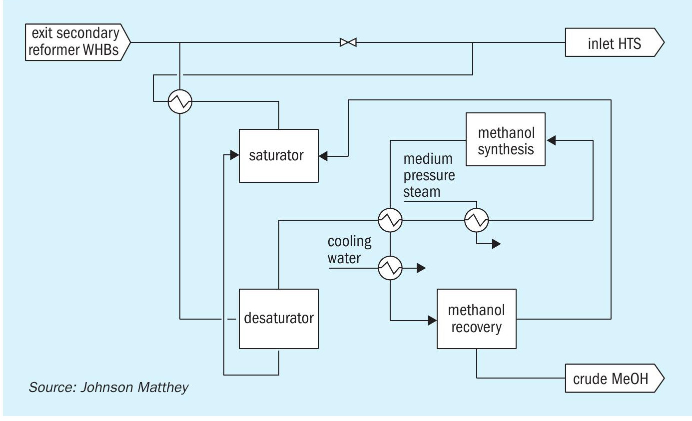
In general, for cases requiring a relatively high production rate of methanol, the carbon oxides level upstream of the high temperature shift (HTS) are most attractive. In this flowsheet, the syngas from the secondary reformer waste heat boilers on the ammonia plant is passed through a desaturation stage to reduce the water content and then heated to methanol synthesis temperatures. A fraction of the CO and CO2 is converted to methanol in a suitable once-through methanol converter. The product methanol is recovered in a crude state and sent to a distillation section for refining to product specifications. The unreacted syngas is passed through a saturation stage to return the removed water to the stream and reheated to the HTS inlet temperature before returning to the ammonia plant. This is illustrated in Fig. 1.
Benefits
Advantages of a retrofit in this form are that there is a single break in and return point to the existing ammonia plant and it has little impact on the operation of the existing equipment.
A once through methanol synthesis system allows the capital cost of the equipment to be kept at a low, reasonable value. The nature of the upstream process on the ammonia plant means that there is a high level of nitrogen in the feed syngas which results in very high flowrates, and therefore high equipment costs, for circulating systems. The configuration also allows for continual operation of the ammonia plant without the methanol section running and for simple start-up of the methanol section in parallel to the ammonia plant.
A benefit of installing the methanol synthesis retrofit upstream of the HTS is that any additional CO slip from the methanol section as a result of methanol synthesis catalyst deactivation can be accommodated in the existing shift section. Therefore, any loss of production of methanol is offset by the increase in ammonia production as a result of the increased hydrogen produced in the shift section. The increase in carbon dioxide exit the shift section is removed in the existing CO2 removal stage.
The once through system is designed such that operation is as simple as possible, and the plant with the retrofit in place can be operated with existing staffing levels.
Ammonia plant impact
Since the synthesis of methanol consumes hydrogen which would otherwise be used in ammonia synthesis, it is necessary to adjust the operation of the existing ammonia plant to maintain a 3:1 H:N ratio in the syngas being fed to the ammonia synthesis loop. The operation of the reforming section can be adjusted such that the syngas leaving the methanol synthesis retrofit is suitable for ammonia conversion.
The front end of the ammonia plant can also be uprated to accommodate some or all of the reduction in ammonia rate associated with the introduction of the methanol synthesis retrofit.
The synergies between the production of ammonia and methanol can be maximised via close collaboration and integration between the design of the methanol synthesis retrofit and the adaptation of the existing ammonia technology. The global strategic alliance agreement between Johnson Matthey and KBR to license ammonia-methanol coproduction processes combines JM’s methanol production process and KBR’s proprietary PURIFIER™ ammonia process. KBR’s PURIFIER technology provides a method of optimising the syngas composition downstream of the methanol synthesis retrofit.
Collaboration between the technology providers can exploit the synergies between the two technologies and reduce the environmental impact of the plant and its opex through shared utilities and lower energy consumption. The interconnectivities between the processes and the design of the methanol synthesis retrofit in close collaboration with the ammonia technology allows for flexibility to optimise production between ammonia and methanol.
Coproduction using syngas exit CO2 removal
Flowsheet
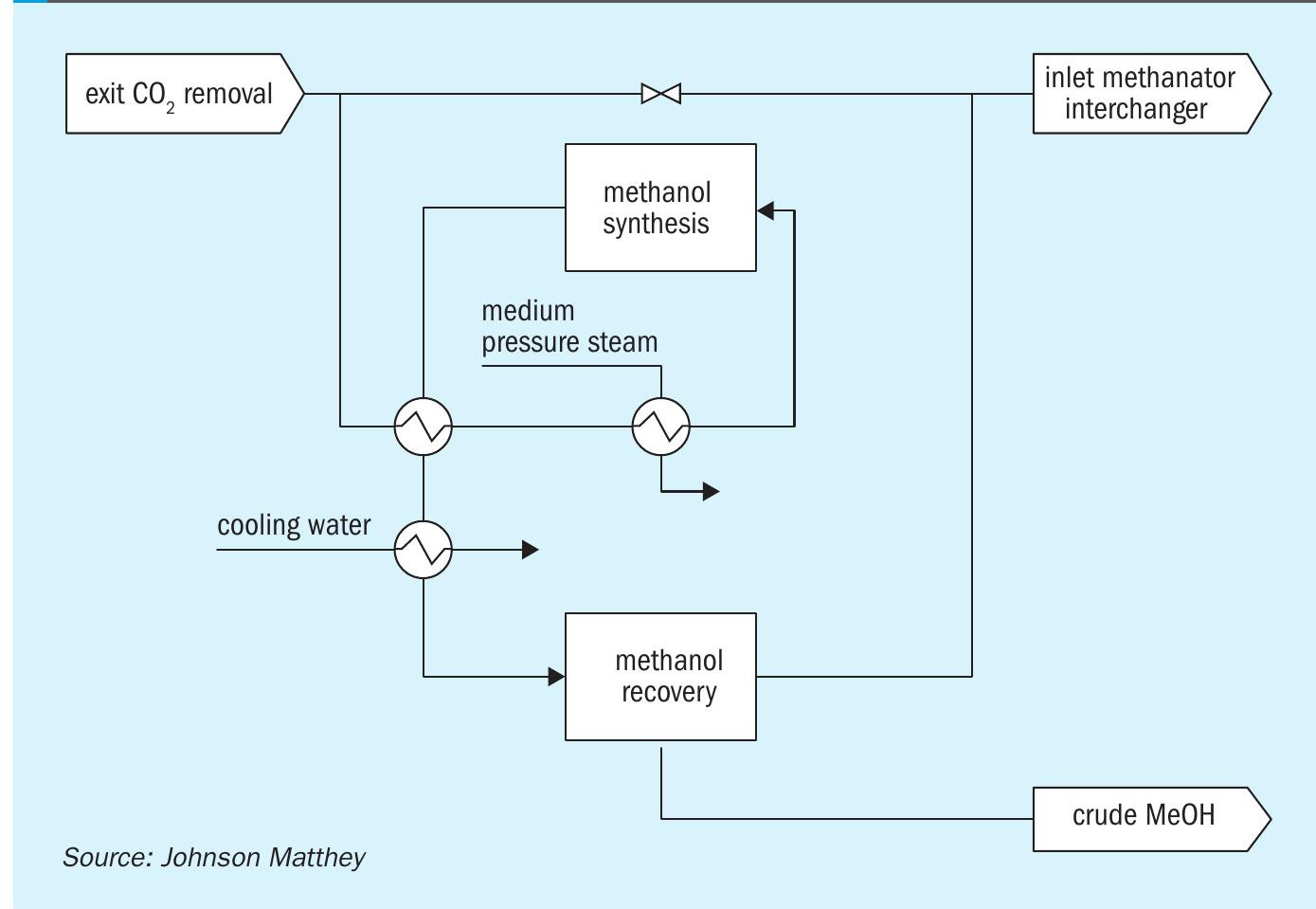
For cases requiring a lower production rate of methanol, the syngas exit the CO2 removal stage can be used. Here, there are low levels of CO and CO2 following the shift and CO2 removal sections, so the maximum methanol capacity is limited. The syngas typically has a water content that is low enough to not require a desaturation stage. The syngas from the overhead of the CO2 removal column is heated to methanol synthesis temperatures. The CO and CO2 is converted to methanol in a suitable once-through methanol converter. The product methanol is recovered in a crude state and sent to a distillation section for refining to product specifications. The unreacted syngas is returned to the ammonia plant. This is illustrated in Fig. 2.
To increase the CO content exit the CO2 removal stage, a portion of the plant flow can be bypassed around the low temperature shift (LTS) converter. Alternatively, the operation of the CO2 removal section can be adjusted to increase the slip of CO2 .
Advantages
Benefits of the retrofit in this form are that there is a single break in and return point to the existing ammonia plant and it has little impact on the operation of the existing equipment. The bypass configuration allows for continual operation of the ammonia plant without the methanol section operating and for simple start-up of the methanol section in parallel to the ammonia plant.
Downstream of the CO2 removal section, the carbon oxides are considered a contaminant since they act as a poison in the ammonia synthesis converter, and carbon dioxide can form ammonium carbamate via reaction with ammonia. Therefore, any carbon oxides in the process are converted to methane in the methanator. The methanation process consumes hydrogen via the reactions:
- CO + 3H2 CH4 + H2 O
- CO2 + 4H2 CH4 + 2H2 O
This hydrogen consumed via methanation cannot then be used in the synthesis of ammonia. Since the conversion of CO and CO2 to methanol consumes less hydrogen than the corresponding methanation reactions, the net effect of introducing the methanol synthesis retrofit is to reduce the hydrogen consumed to convert the residual carbon oxides. This allows for a higher flow rate of hydrogen to the ammonia synthesis section, and if the synthesis loop and associated equipment is capable, allows for an increase in the production of ammonia.
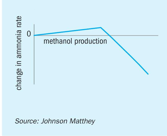
Note that increasing the CO or CO2 at the feed to the retrofit section via a partial bypass of the LTS or modification of the CO2 removal section will increase the carbon oxides slip from the methanol synthesis section. These carbon oxides consume hydrogen in methanation and will reduce the potential ammonia production rate. Eventually, the increased slip will offset the benefit on hydrogen consumption of synthesising methanol over methanation (Fig. 3).
The once through system is designed such that operation is as simple as possible, and the plant with the retrofit in place can be operated with existing staffing levels.
For significantly higher required methanol production rates, this illustrates how a retrofit using syngas exit the CO2 removal stage is less suitable than one using syngas exit the secondary reformer.
Ammonia plant impact
There is a lesser impact on the ammonia plant for a retrofit using syngas exit the CO2 removal stage since the methanol synthesis is using a smaller flow of CO and CO2 than that upstream of the shift section.
As discussed above, there may be a benefit to ammonia production as a result of the methanol synthesis retrofit. For cases requiring higher CO and CO2 in the feed, the ammonia production may be reduced. Some, or all, of this reduction in rate may be accommodated by uprating the ammonia plant syngas generation section, and an assessment of the optimal technology configuration can be made on a case by case basis in close collaboration with the ammonia technology provider.
A reduced exotherm over the methanator as a result of lower CO and CO2 levels in the methanator feed means that additional heating will be required to achieve the methanator inlet temperature. The effect of the increase in heating required can be mitigated with collaboration between ammonia and methanol technology providers and the optimal integration of the flowsheets.
Integrated UFC
Urea formaldehyde concentrate (UFC) is used to condition a granular urea product and some prilled urea products. UFC is added to the urea product in small quantities, which renders a standalone production facility for an individual urea producer unfavourable economically. Therefore, urea producers typically import purchased UFC from third party distributors (Fig. 4).
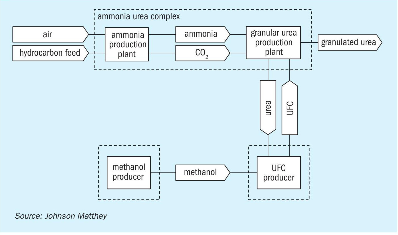
UFC producers would normally purchase a methanol feedstock at market value, which includes the margins of the methanol producers. The imported UFC cost also allows for the third-party producer’s margins, and the cost of transportation to the urea producer. This raises the opportunity for significant savings to a urea producer were it possible to manufacture the necessary UFC on the ammonia-urea complex.
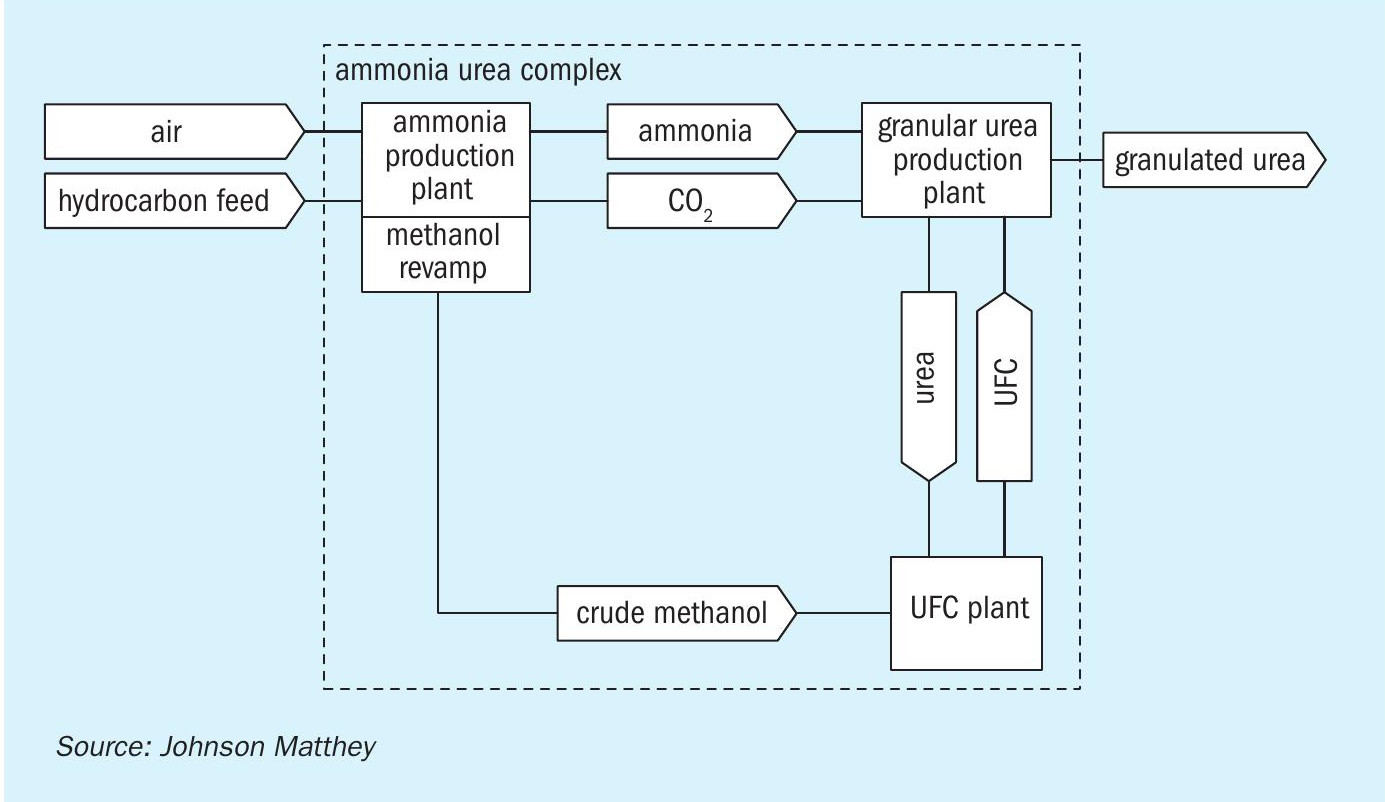
The interconnectivities between the production of ammonia, urea and formaldehyde can be exploited to offer a retrofit to existing ammonia plants to produce UFC for conditioning the urea product (Fig. 5). In the iUFC™ process, formaldehyde is produced via the oxidation of methanol, and methanol can be produced using a retrofit as described earlier. The modest capital costs of a well-designed retrofit section can allow the savings of in-house UFC production over purchased UFC to be realised.
UFC production
Production of formaldehyde and UFC uses well established technologies. The Johnson Matthey FORMOX™ process employs mixed oxide catalyst technology due to its superior yield, high steam production and because it makes it possible to produce UFC-85 directly in the same plant.
Formaldehyde is produced via the partial oxidation of methanol with air as an oxidising agent:
2CH3 OH + O2 → 2CH2 O + 2H2 O
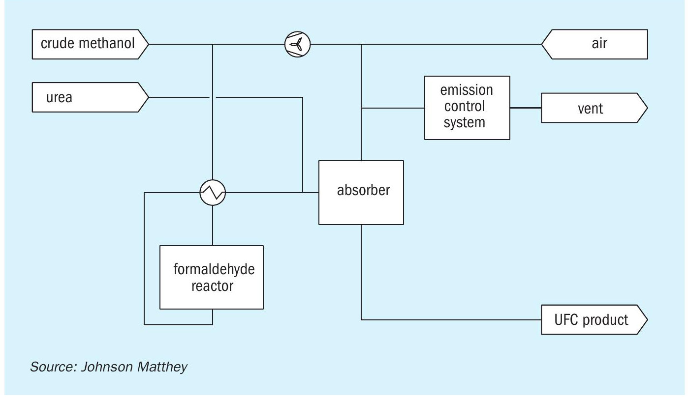
The product stream from the formaldehyde synthesis reactor is sent to a water absorber column. The formaldehyde is absorbed into the water, the water condensed, and any unreacted air is recycled to the formaldehyde synthesis reactor. A purge stream is taken from the recycle gas which is released to the atmosphere after treatment in an emission control system to convert the trace methanol, formaldehyde and CO to carbon dioxide and water. The formaldehyde in the absorbed water is absorbed into a urea solution to produce a UFC product at the required concentration. This is illustrated in Fig. 6.
Integrated UFC production
Standard Johnson Matthey FORMOX™ plants are designed with flexibility in mind and either UFC-85 or formaldehyde can be produced on the same plant. The plant can also be configured to produce UFC concentrations other than 85%.
When retrofitting an ammonia urea complex for the integrated production of UFC, the UFC plant can be designed to operate with crude methanol. This allows for capital and operating cost savings in the distillation of the crude methanol product from the methanol synthesis retrofit. Further integration is also possible and can be offered on a case by case basis.
Johnson Matthey FORMOX
Johnson Matthey FORMOX has been developing and selling formaldehyde technology and catalysts since the late 1950s and has supplied more than 20 million t/a (as 37 wt-%) capacity to a wide range of customers. To put this into context, global demand in 2015 was about 45 million t/a. By carrying out both catalyst and technology development in the same organisation, any catalyst development can easily be implemented in the flowsheet and vice-versa. Johnson Matthey FORMOX typically acts as an engineering and procurement contractor during the project phase and assists during erection and commissioning. After start-up Johnson Matthey FORMOX continues to support plant operation with an extensive technical support program.
Johnson Matthey FORMOX has continuously improved the formaldehyde catalyst and technology and today its customers produce more than four times as much formaldehyde in the same size reactor as in the early 1960s. This increase in production also comes with a considerably improved yield, less than half the power consumption and more than double the steam generation.
The integration of the UFC plant and the methanol synthesis retrofit on the ammonia plant can integrate the utility requirements to optimise the operating costs of the two processes.
Benefits
As discussed above the main benefit of the iUFC process is the reduction in the cost of UFC since the integrated process eliminates the premium of the third-party producer for methanol or UFC and the transport costs. The operating costs for the UFC process are minimal in comparison to the ammonia-urea complex. The potential savings are assessed on a case by case basis and can be maximised by optimising the integration of the iUFC process. Typically, the savings are of the order of the purchase cost of the UFC.
Typically, the required rate of methanol production for an iUFC process means that the methanol synthesis retrofit using the syngas exit the CO2 removal stage is most appropriate. Therefore, the benefits outlined previously are also applicable here. The flexibility of the methanol synthesis retrofit means that there is no impact on ammonia plant reliability and standard storage designs can be provided for intermediate storage of crude methanol to accommodate catalyst changes in the methanol and formaldehyde synthesis systems.
ARVOS / SCHMIDTSCHE SCHACK
Improving plant reliability with a new process gas cooler
The steam system in ammonia plants can have a big impact on the overall reliability of the plant. Steam is used at different pressure levels for the process itself, as well as providing the driving power for the process compressors. The steam is produced by waste heat recovery from the process and additional natural gas fired auxiliary boilers. Depending on the plant scenario, modern steam systems are designed for zero steam export, export steam to produce electricity, or in the case of an ammonia/urea complex, to supply steam or electricity to the urea plant, which is a consumer of both.
In ammonia plants, a major part of the steam generation by waste heat recovery takes place downstream of the secondary reformer. The waste heat boiler package, at a minimum, consists of a horizontal or vertical process gas cooler (PGC) with a steam drum, operating with natural circulation of the water/steam. Damage to the PGC is the main cause of poor performance of the steam system and unexpected plant shutdowns.
Reasons for PGC failures
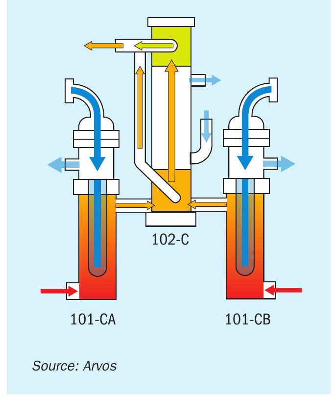
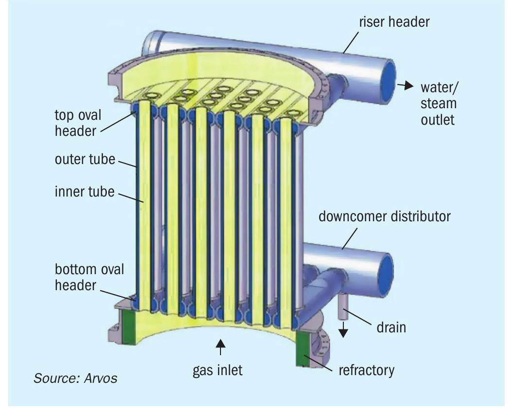
Most of the world’s ammonia plants built between 1960 and 1990 are equipped with vertical PGCs downstream of the secondary reformer. A typical arrangement is shown in Fig. 1. The effluent gas enters two parallel primary PGCs at a temperature level around 1,000°C. The primary PGCs are connected to a vertical secondary PGC. The secondary PGC is equipped with an external by-pass to control the gas outlet temperature.
During the last ten years, reliability issues, damage and failures of both PGCs have been reported in various conference papers.
The primary PGCs (101-CA/CB) have a vertical bayonet water tube type design. The process gas enters the PGC at the bottom and flows turned by baffles upwards in co-current flow with the boiler water (BW). The shell is completely refractory lined on the inside and has a water jacket on the outside. The bayonet tube is a tube-in-tube design; in general this design, with boiler water flowing in the annular gap, is an excellent solution for a heating surface. In the bayonet design the water enters the end cap of each tube through a coaxial open-ended inner tube and flows upwards through the annular space between the inner and outer tube walls. As the inner and outer tubes are held by different tube sheets, the bayonet tube boiler design avoids the critical problem of tube sheet stress caused by thermal expansion of the tubes, which virtually disqualifies conventional shell-and-tube designs for this application.
However, the bayonet tubes of the PGC have several inherent reliability issues, in particular:
- Sludge deposition in the end cap/ pocket of the bayonets: deposits in the BW agglomerate in the end cap and reduce or inhibit the cooling capability. In addition, the cap is the section of the bayonet with the highest heat flux and consequently this leads to local overheating. The situation gets worse when operating above the nameplate capacity.
- Tube vibration: since the process gas is turned by baffles, there is always the risk of flow induced tube vibrations and tube failure.
- Problems during start-up since the direction of the water/steam circulation are not clearly defined.
Damage to the tube bundles of these boilers is the main cause of unexpected shut-downs in ammonia plants. The boiler is high maintenance with the tube bundle needing frequent replacement. This requires a spare bundle that also has to be maintained ready for the next replacement. Spare inventory also ties up capital with additional negative financial impact.
The secondary PGC (102-C) is a standard shell-and-tube in a vertical fire tube design. The process gas enters the PGC at the bottom and flows upwards in co-current flow with BW. As already discussed, this design principle has inherent reliability issues due to sludge deposition at the lower tube sheet, which can lead to overheating and failure of tube-to-tube sheet welding, and steam blanketing at the upper tube sheet. Due to mechanical reasons, riser nozzles cannot be located as close to the upper tube sheet as required. Consequently, steam bubbles agglomerate which leads to reduced cooling of the upper tube sheet and failure of tubeto-tube sheet welding.
A reliable design of a vertical PGC is always challenging. For that reason Schmidtsche Schack’s philosophy was not to develop a completely new design, but to apply and adapt a proven design to achieve a reliable solution.
A proven design
The basic element of this proven solution is the Schmidt’sche® double tube system (see Fig. 2). It combines the advantages of the fire and water tube design and comprises a row of coaxial double tubes welded at each end to a horizontal header with an oval cross-section. A PGC is made up of a multiple array of these tube/header assemblies, with the headers welded together to effectively form hollow tube sheets.
The water side of the exchanger operates in natural circulation. Water from the steam drum is fed through the downcomer piping to the bottom oval headers and flows upwards through the annulus between the inner and outer tubes, where it is partially converted to steam, and into the upper headers, which discharge into the riser manifold. As the ‘tube sheets’ are cooled by the water/steam flowing through the tube headers, there is no need to protect the tube sheet with a refractory layer. This reduces the use of refractory and has a positive effect on the reliability of the PGC and plant.
The process gas flows through the inner tubes and is cooled by the water/ steam mixture in the annulus between the inner and outer tubes.
Each process tube in the Schmidt’sche® double tube exchanger thus has its own cooling element provided by the outer tube. Variations in the heat load on the individual tubes are automatically accommodated by the proportion of the water that is converted to steam.
Due to the clearly defined flow path on the water side and on the gas side there is no risk of flow induced vibrations.
Since the BW flow from bottom to top is clearly defined, on the one hand there is no risk of sludge settlement at the bottom or steam bubble agglomeration at the top. On the other hand, the direction of natural circulation is predetermined during start-up.
High water flow velocities with high turbulence intensively cool the oval headers (tube sheet) and each tube. Consequently, a reduced wall thickness can be realised which leads to lower wall and material temperatures. This results in low thermal stresses at the tubes and tube-to- tube sheet welding. In addition, the oval header, a key design feature, enables easy accommodation of differential thermal expansion between the inner and outer tube, which also results in favourable stress patterns.
The robustness of the Schmidt’sche® double tube system is ensured by full penetration and crevice free welds of the inner and outer tube. Crevice corrosion is therefore avoided and due to water cooling at the weld position, the temperature at the welds is low.
Reference applications
The vast majority of Schmit’sche® double tubes systems are used in the petrochemical industry in steam cracking processes for olefin production. However, in the last 20 years approximately 19 units of double tube heat exchangers have also been installed downstream of the gasifier in coal, pet-coke and biomass gasification processes, where the syngas atmosphere is more severe than in ammonia plants. Gasification plant are more problematic than ammonia plants and experience higher fouling, higher metal dusting and higher hydrogen attack due to the higher partial pressures of hydrogen, carbon monoxide and carbon dioxide as shown in Fig. 3.
The process conditions, as well as the size and weight of the double tube design, for replacing 101-CA/CB in a typical ammonia application are within the existing experience of ethylene and gasification plants.
Revamping options
The boilers downstream of the secondary reformer (101-CA/CB and 102-C) can be replaced in three different scenarios:
- One-by-one: each of 101-CA/CB and 102-C can be replaced by a new PGC.
- Two-in-one: both 101-CA/CB will be re-placed by one big 101-C. 102-C will be replaced separately. The existing by-pass for temperature control also remains.
- Three-in-one: all three boilers will be re-placed by one big PGC including temperature control.
The greatest customer benefit is achieved by a one-by-one replacement for the following reasons:
- Usually the existing foundation inside the existing steel structure is suitable for the new PGCs (preliminary analysis can assess this issue); the installation of a new big foundation will be avoided.
- No additional plot space for the new PGC is required (which would reduce the available space for maintenance activities).
- The existing gas transfer lines can be used; the installation of a new long and big transfer line connecting the secondary reformer to the new big PGC is expensive and could be a safety concern due to operation at high pressure and temperature.
- The existing water/steam piping can be used with minimal adjustments. In case of a new big PGC this piping has to be considerably extended.
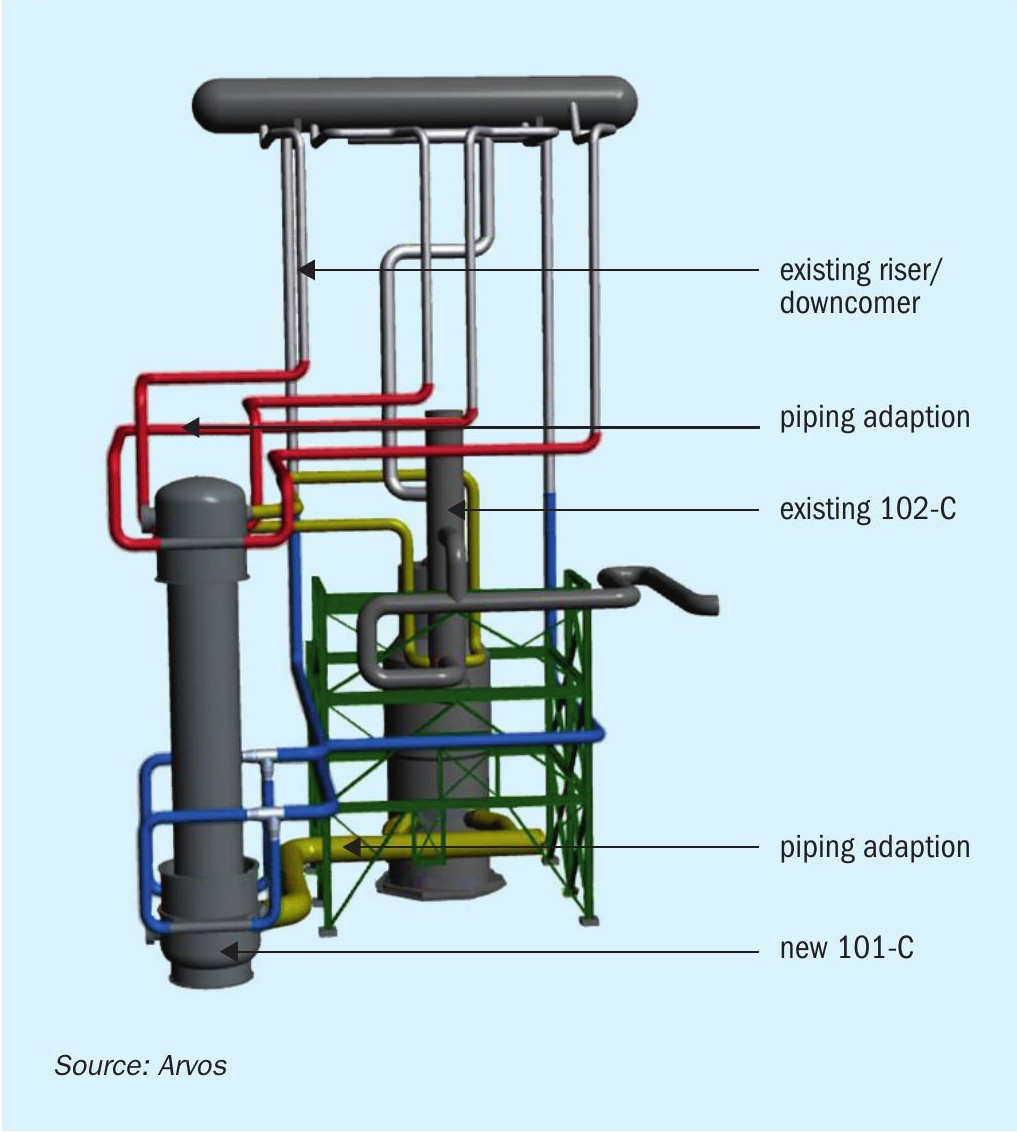
Fig. 4 shows an example of the one-by-one replacement of 101-CA/ CB. The new 101-CA/CB was designed for 2,000 t/d, a capacity upgrade from nameplate capacity (1,360 t/d). The real arrangement of an existing plant was 3D laser scanned by Casale SA. The data were transferred into a CAD model. This approach ensures full transparency in the design phase and allows any issues to be detected early in the project phase.
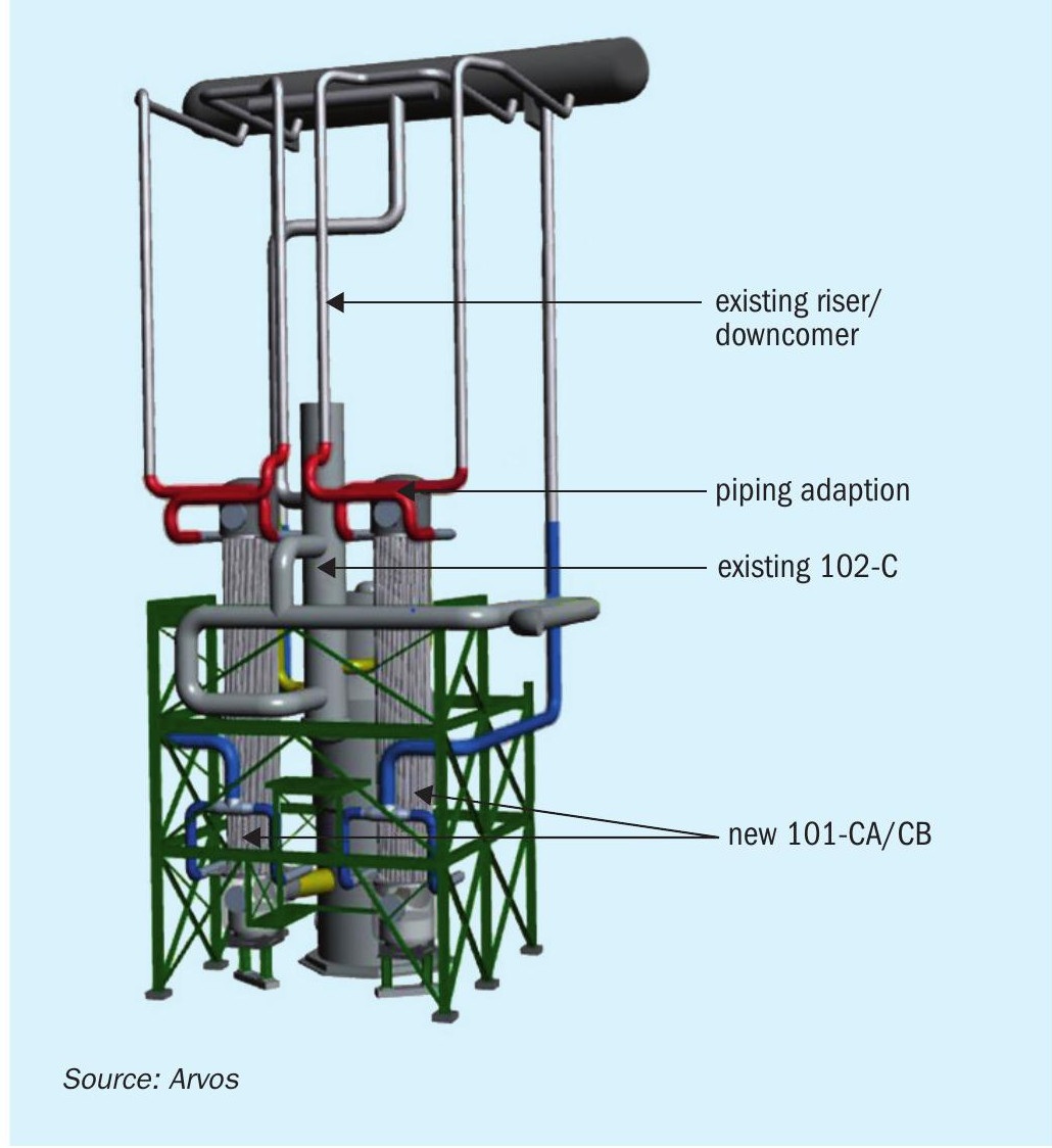
The new PGC fits into the existing steel structure on the existing foundation. Adjustments to the existing riser/downcomer piping are very limited (coloured red/blue).
The double tube technology is flexible enough for all revamping scenarios depending on customer needs and requirements. Fig. 5 shows an example of the replacement of the 101-CA/CB with one PGC. The major extensions of water/steam piping as well as the gas transfer line can be clearly seen. In this case, the new PGC requires a new plot space outside the existing steel structure.