Sulphur 392 Jan-Feb 2021

31 January 2021
Fire prevention and suppression for molten sulphur tanks and pits
SULPHUR SAFETY
Fire prevention and suppression for molten sulphur tanks and pits
Fires are known to occur in sulphur storage pits and tanks somewhat frequently due to the presence of both flammable material and air, so methods for preventing and extinguishing these fires are critical. D. J. Sachde, K. E. McIntush, C. M. Beitler, and D. L. Mamrosh of Trimeric Corporation review fire suppression methods used in the industry including snuffing/sealing steam, rapid sealing, water mist, and inert gas blanketing. Protective tank design features to reduce the likelihood of a sulphur fire are also reviewed. Benefits and limitations, design considerations, and recommended guidance for suppression and preventative measures are discussed.
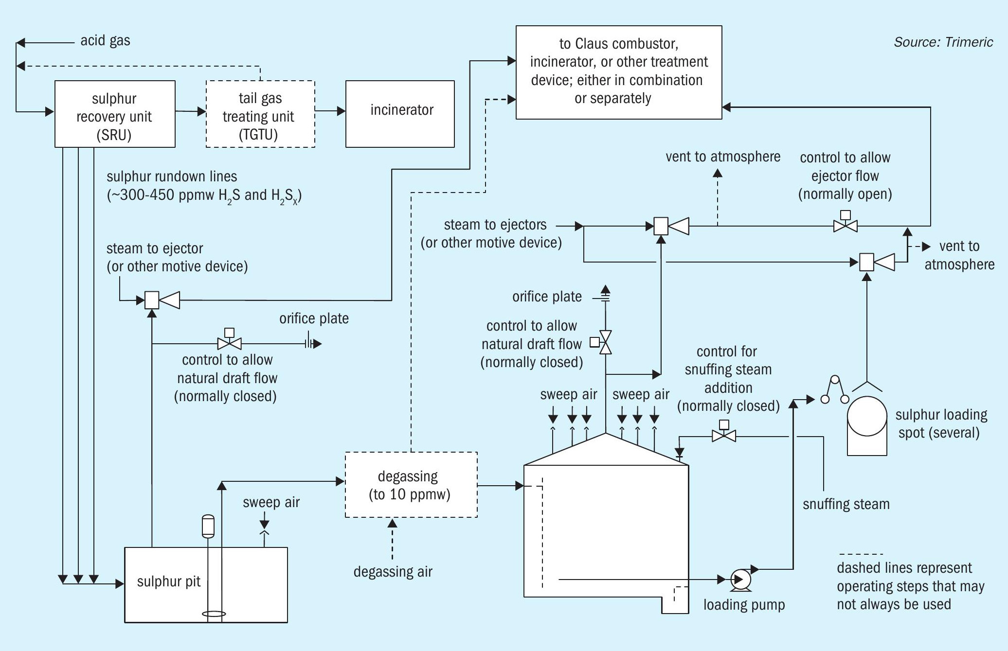
Hydrogen sulphide (H2S)is a byproduct of processing natural gas and refining crude oils, which generally must be removed and controlled. A modified Claus sulphur recovery unit (Claus SRU) is a method for converting the removed H2 S to molten elemental sulphur. The molten sulphur from a Claus SRU is stored and handled in several steps, as depicted in Fig. 1.
The sulphur from the Claus unit often flows to a sulphur pit or receiving vessel and contains approximately 300 ppmw H2 S and H2 SX 2,3,4 although oxygen enrichment and subdewpoint operation can produce higher H2 S levels, e.g. 450 ppmw5 . The sulphur may be degassed in the pit or in separate equipment to reduce H2 S concentrations to ~10 ppmw. However, undegassed sulphur is common and should be considered in any molten sulphur handling design in the event the degassing system is not functioning. The molten sulphur often flows from the pit to a storage tank for offloading and transport.
The storage pit and tank represent areas where explosive vapours may accumulate and other hazardous conditions may develop as part of the operating conditions of the system6 . Multiple sulphur species may be present and should be considered when evaluating the risks of the system7,8 . This article focuses on the hazards associated with sulphur fires in molten sulphur storage applications. A summary of industry guidance, standards, and/or common practices for preventing and suppressing sulphur fires is presented.
Fire and explosion hazards in molten sulphur storage
Flammable components
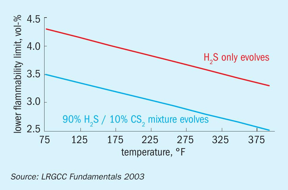
Hydrogen sulphide is present in the molten sulphur and vapour space of storage and handling equipment. The flammability window of H2 S is denoted by upper and lower explosive limits (UEL and LEL). In molten sulphur handling applications, the LEL is of practical concern since concentrations approaching the UEL are not expected based on the equilibrium concentrations of H2 S in the vapour. Fig. 2 depicts the LEL of H2 S as a function of temperature2 . Note that more recent literature data on the LEL of H2 S differs slightly from the figure (e.g., at 330°F/166°C, the newer data indicates the LEL of H2 S is ~3 vol-% H2 S)9 .
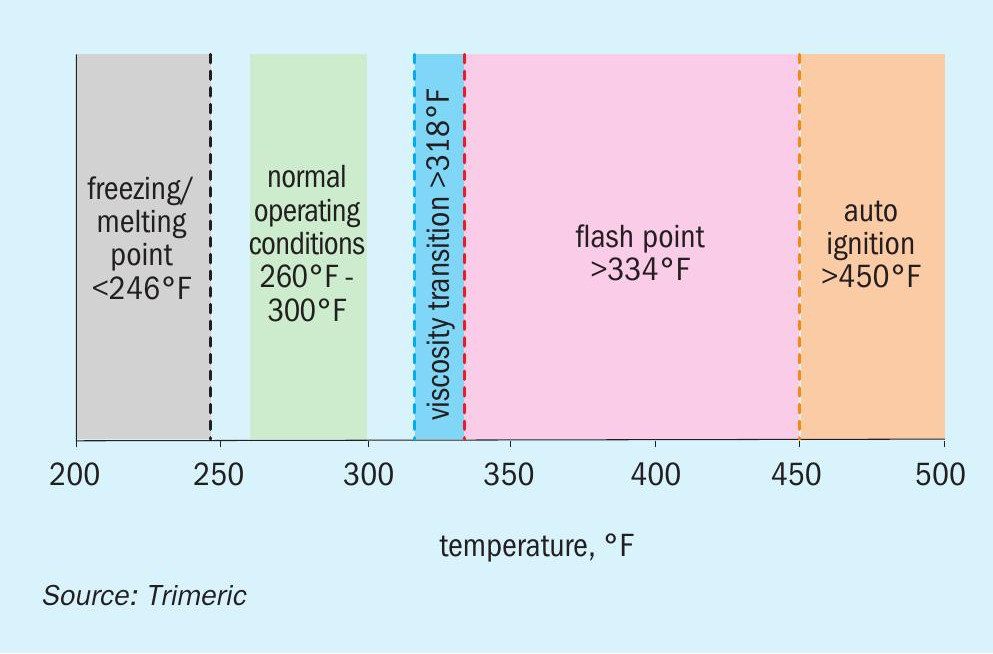
If a fire is ignited, the molten sulphur itself can serve as fuel. In addition, elemental sulphur has a flash point as low as 334°F/168°C2 . If the sulphur handling equipment is operated above the flash temperature, the risk of fires increases significantly. Furthermore, the auto-ignition temperature of elemental sulphur is as low as 450°F/232°C10 . While this is well above the normal operating temperature of molten sulphur storage systems, localised hot spots approaching the auto-ignition temperature could be a source of fires. Fig. 3 depicts the operating window for molten sulphur given its unique properties.
Finally, NFPA-655 cites 309°F/154°C as a transition temperature for the design of molten sulphur storage equipment. Above 309°F, additional design requirements apply (e.g., deflagration vents)11 . Field experience reported in the literature12 and Trimeric’s first-hand knowledge of operator experience supports the implication that bulk temperatures above 309°F are associated with increased frequency of sulphur fires, even though this is well below the sulphur vapour flash point.
Ignition sources
For sulphur below its auto-ignition temperature but within its flammability window, fires nominally require an ignition source. In molten sulphur applications, ignition sources include: l Static discharge accumulated by free-falling sulphur2,12 : Molten sulphur is an electrical insulator and can accumulate static charge when falling through air. This leads to a risk of electrostatic discharge that can serve as an ignition source.
(Note that, while the authors are not aware of any incidents where air moving over a stagnant molten sulphur surface (e.g., sweep air in a tank) have led to sulphur fires, the mechanism for static charge generation is similar to free-falling sulphur (i.e., relative velocity and associated friction between the air and the molten sulphur). Therefore, some have hypothesised that air sweeps over molten sulphur could pose a static discharge risk12 .)
- Hot surfaces in equipment: Rotating equipment may be susceptible. For example, failing pump bearings may lead to increased friction and localised hot spots.
- Improper operating temperature: This can occur from improper temperature design targets (e.g., operating above 309°F) or improper use of heating medium in storage applications (e.g., using steam with a temperature above the flash point of sulphur, i.e., above ~80 psig/f~5.5 barg, if saturated steam is used).
General ignition sources in an operating facility, e.g., sparks generated by maintenance work, also pose a risk and must be considered in sulphur handling areas.
Pyrophoric iron sulphide formation
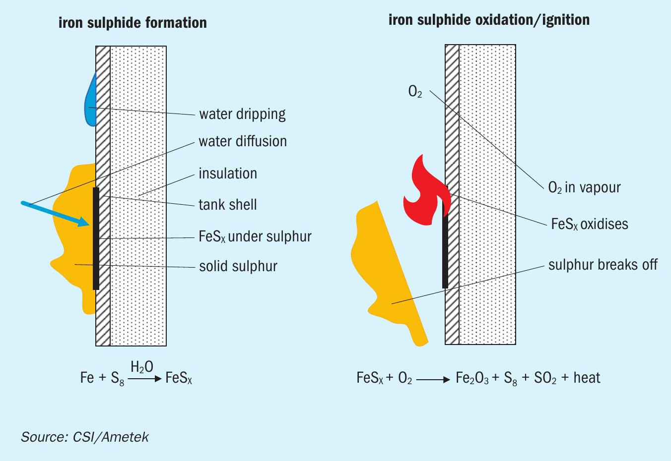
The formation of pyrophoric iron sulphide is a unique risk that exists in carbon steel equipment where H2 S and/or elemental sulphur and water are present in an anaerobic or reducing environment13 . For example, in a carbon steel molten sulphur tank that is purged or blanketed with an inert gas (e.g., nitrogen), iron sulphide can form on internal tank surfaces. When water is present (e.g., via steam leaks), corrosion of carbon steel occurs yielding iron sulphide on the tank surface14 (see ref 14 for chemistry discussion). The iron sulphide does not present a risk on its own. However, if iron sulphide is exposed to oxygen (e.g., via air during tank maintenance), a pyrophoric reaction can lead to fires and/or explosions. In molten sulphur handling systems with sweep air, iron sulphide that is formed is generally oxidised quickly in a controlled manner, preventing accumulation to levels where the pyrophoric reactions can occur. However, even in systems with continuous air sweep, if significant deposits of solid sulphur accumulate on tank surfaces, it may limit access of the oxygen to the tank surface, allowing iron sulphide to form and accumulate (Fig. 415 ). Therefore, internal tank surfaces that accumulate solid sulphur deposits are a safety concern.
Fire prevention
Industry standards and guidance
NFPA-655 (“Standard for Prevention of Sulfur Fires and Explosions”) is a primary industry reference for fire prevention in molten sulphur handling applications. Chapters 5 and 6 (2017 edition) are related to molten (“liquid”) sulphur handling. Chapter 5 applies to NFPA-defined normal handling temperatures (246°F-309°F). Chapter 6 applies to sulphur above 309°F. NFPA-655 includes guidance on the following preventative measures:
- Design for normal handling temperatures
– Detection of unsafe conditions (e.g., H2 S monitoring)
– Equipment design (e.g., tank feed/ fill line extension to tank bottom to minimise free-fall and agitation when feeding sulphur)
– Vent systems (e.g., heated vent system design to prevent molten sulphur solidification)
– Bonding and grounding (e.g., bonding and grounding of sulphur lines, tanks, loading trucks/cars)
– Open flames and sparks (e.g., appropriate conditions for activities involving open flames/sparks such as welding).
- Design for handling temperatures above 309°F
– All of the guidance for normal handling temperatures apply.
– Equipment design: Recommends design of equipment to be “closed as tightly as possible to prevent escape of vapour and to exclude air”, signaling a different approach to fire prevention than sweeping with air to stay below the LEL.
– Deflagration venting: Refers to NFPA 68 for deflagration venting design and covers other design considerations associated with deflagration vents (heating of vents/ducts, need for an inerting agent, etc.).
In addition to NFPA-655, NFPA-68 is relevant for deflagration venting and NFPA-69 (Standard on Explosion Prevention Systems) includes information on preventing and managing explosions/deflagrations. NFPA-69 identifies two approaches to prevent combustion: i) Combustible concentration reduction, ii) Oxidant concentration reduction. The standard provides a discussion on each approach (Chapter 7, 8, and Annex B in 2018 Edition).
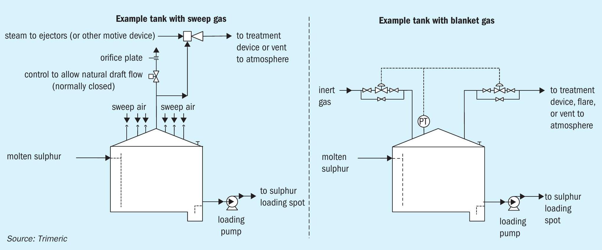
Minimising combustible component concentration – Use of sweep gas
Sweep gas is often used to dilute the H2 S concentration in the vapour space of storage equipment. Different sweep gases have been used including air, nitrogen, fuel gas, steam, combustion product gases, and CO2 . Many molten sulphur storage tanks are swept with air because it is readily available and inexpensive. The flammability concerns with air (oxygen) can be mitigated by maintaining a safe margin below the LEL and installing monitoring equipment. Using 25% of the LEL is a common industry practice for calculating the sweep air flow rate requirement; values as low as 15%16 and as high as 35%11 as an upper limit to stop operation have been reported. The presence of oxygen also keeps the tank atmosphere in an oxidising state, which prevents the formation of pyrophoric iron sulphide.
Other sweep gases (e.g., nitrogen, fuel gas, steam) have been used but are not as common because of the risk of pyrophoric iron sulphide formation, limited availability of the gas, and introduction of combustible materials to the tank, among other reasons. Details of the sweep gas approach are presented elsewhere17,18,19 . See the September-October 2020 issue of Sulphur for more details on sweeping and blanketing of gases18 .
Minimising oxidant concentration — Inert gas blanketing
Another method to prevent fires and explosions in sulphur tanks is to blanket the tank with inert gas to limit the oxygen content in the vapour space by preventing air ingress. As shown in Fig. 5, the blanket gas (e.g., nitrogen) is fed to or removed from the tank to maintain a constant, slightly positive, pressure as inbreathing or out-breathing occurs (primarily via liquid movement). The flow of N2 in “blanket” mode is intermittent and typically less than the gas requirement in “sweep” mode. The blanketing method may be used if a site does not have the means to handle and/or treat the large continuous sweep gas flow. However, inert gas blanketing can result in a significant amount of H2 S accumulating in the vapour space that can create an explosion hazard if oxygen is unintentionally introduced to the tank. Inert gas blanketing also results in increased formation of pyrophoric iron sulphide, and a source of the inert gas is required. For these reasons, the use of inert gas blanketing to prevent molten sulphur tank explosions is less common than the use of air sweep. Another blanketing technique using gas with oxygen below the limiting oxygen concentration (LOC) is also presented in the literature16,18,20,21,22 .
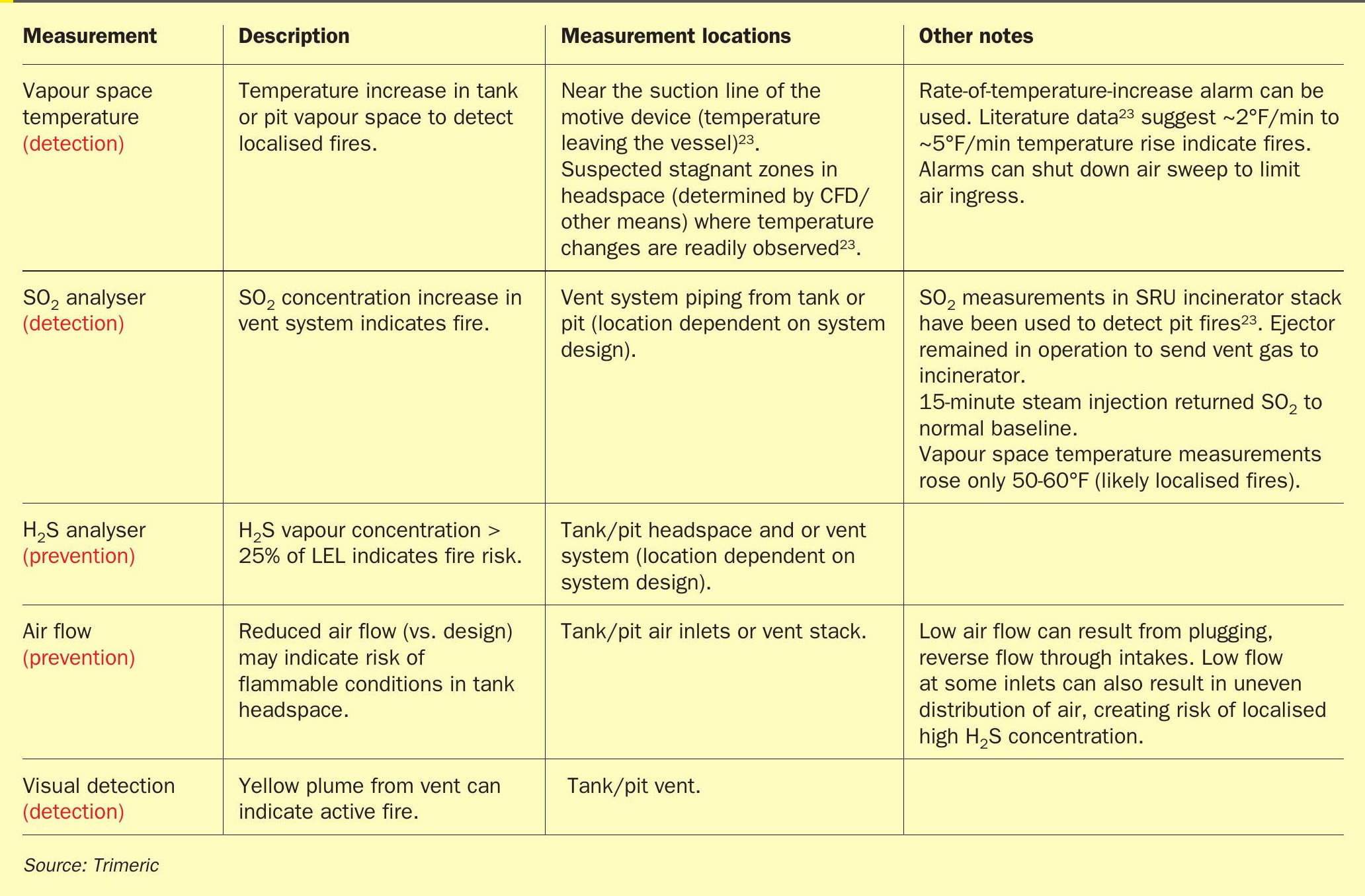
Fire prevention and detection design features
The design of the molten sulphur pit or tank should include features to mitigate and detect sulphur fires such as those in Table 1.
Fire suppression
Industry standards and guidance
NFPA-655 is a primary standard for fire suppression in molten sulphur handling operations. In the 2017 edition11 , Chapter 5 (normal handling temperatures, 246-309°F/119-154°C) and Chapter 6 (handling sulphur above 309°F) contain relevant information on fire suppression. The box to the right summarises some of the fire suppression topics covered in the standard (2017 edition)11 .
Fire suppression industry standards and guidance
1. Firefighting methods (Section 5.5 in NFPA-655) for covered liquid sulphur storage tanks, pits, and trenches:
- Inert gas system designed according to NFPA 69.
- Steam extinguishing system capable of delivering a minimum of 2.5 lb/min of steam per 100 ft3 of volume (“snuffing steam”).
– In Annex A (Section A.5.5.1(2)), a design recommendation that snuffing steam “should be preferably introduced near the surface of the molten sulphur” (via NFPA 86, Section F.3).
- Rapid sealing of the enclosure
– The only rapid sealing method explicitly discussed in the current NFPA-655 standard is sealing steam application (Annex A, Section A.5.5.1(3)).
- Sealing steam is applicable to enclosed sulphur tanks or pits designed with sweep air systems that meet the requirements of NFPA 69. Steam delivered at a minimum rate of 1 lb/min per 100 ft3 of tank or pit volume is “expected to develop a positive pressure in the enclosure, thereby sealing the sulphur tank or sulphur pit and preventing air ingress and extinguishing the fire.”
- The standard includes additional guidance on sealing steam, referencing the originating literature23 .
– The standard does not specifically exclude other means of “rapid sealing”, including closing off vessel inlets and outlets.
- Prior versions of NFPA-655 did explicitly refer to “…closing the container to exclude air…”; there was also language referring to small vessel sizes for this practice24 .
- In the authors’ opinion, extreme caution is advised regarding mechanical sealing of a vessel as a fire mitigation technique.
2. For open containers, fine water sprays are deemed acceptable for fire extinguishing.
3. For storage equipment operating above 309°F:
The standard indicates that storage equipment should be designed to exclude air under normal operation, so sealing methods for fire suppression are not applicable. The standard does indicate that an “adequate” supply of an inerting agent, such as steam, must be available “at all times for blanketing and purging equipment.”
Snuffing and sealing steam
NFPA-655 makes a distinction between snuffing and sealing steam. Snuffing steam is used to directly extinguish a fire by displacing air at the fuel-fire interface with steam, removing the oxygen needed for combustion. Sealing steam is used to effectively “seal” the tank/pit by continuously introducing steam to the headspace and generating a positive pressure in the vessel. This prevents additional air ingress, extinguishing the fire after any oxygen in the headspace is consumed.
The addition of “sealing” (as opposed to “snuffing”) steam in NFPA-655 was based on the overpressure risk for typical air-swept tank and pit designs subject to the snuffing steam requirement23 . Analyses indicated that the snuffing steam requirement of 2.5 lb/min/100 ft3 of tank volume was often impractical to vent from air swept tanks and pits when balancing overpressure risk from the steam (large air inlets required to vent steam) against normal air intake (smaller inlets to prevent reverse flow)23 . A lower sealing steam rate (1 lb/min/100 ft3 ) was proposed based on industry feedback and steam flow evaluation via CFD.
Design and operating considerations
Sealing and snuffing steam systems have several considerations outside of the fire suppression function/flow requirements. Key design considerations include:
- Location of the steam activation valve: Industry practice is that the valve (typically manual) should be at least 50 ft from the tank (radially) to ensure the valve operator is safely removed from the hazard area23,3 . The valve should be located in a place where the operator has a clear line of sight from the valve to the tank vent(s) to verify steam activation.
- Verification of dry steam: The design should include provisions for blowdown of steam prior to activation to ensure only dry steam is present in the line. Wet steam can create a tank rupture risk (larger mass of water reaches and vaporises/expands in the tank). The steam system should include a drip leg and steam trap upstream of the valve to ensure condensate does not accumulate in the line and the line stays warm23 .
- Minimise the risk of plugging: To prevent sulphur plugging of the steam line, the line may have rupture disks at the tank. Alternatively, the line can use a small purge gas flow to prevent back flow of sulphur vapour and/or be thoroughly steam jacketed or traced to prevent plugging. The sealing steam line operation should be verified periodically to ensure plugging has not occurred.
- Some references also indicate that sealing steam should be introduced close to air inlet nozzles so that the steam rapidly exits via the air inlets11,23 . In practice, if sufficient steam is introduced to generate positive pressure in the tank (i.e., force tank vapour out of the air inlets), the sealing effect of the steam should still be effective even if the vapour that initially leaves the inlets is headspace vapour (rather than steam). However, benefits of having the steam leave rapidly to form the “seal” may include:
– Limiting the rapid expulsion of the toxic headspace vapours to the atmosphere and immediate vicinity as the steam enters.
– Quick visual verification that the steam has reached the tank (exiting the air inlets).
(Note: It is important to distinguish between sealing steam, where it is recommended to introduce the steam near the air inlet nozzles and snuffing steam, where it is recommended (in NFPA-655) to introduce the steam close to the molten sulphur surface. The difference in the primary mechanism to extinguish the fire for each application explains the different recommendations for steam introduction.)
While the NFPA guidance for sealing or snuffing steam flow can be used directly as the basis for a steam fire suppression system design, several independent engineering checks can be performed to validate the steam rate (NFPA recommended or other steam rate):
- Verify positive pressure generated by the steam is sufficient to “seal” the tank/pit across a range of operating conditions (normal air sweep flow, air forced into the tank by wind effects, etc.).
- Check over-pressure risk once the maximum possible steam flow is finalised.
- Use CFD analysis to confirm adequate performance of sealing steam.
In Trimeric’s experience, some sites do not have enough steam to supply the 1 lb/min/100 ft3 sealing steam as recommended in NFPA-655. Literature suggests that fires can be suppressed even if the steam rate is lower than in NFPA-65523 , and Trimeric’s contacts in industry also indicate that lower steam rates are successfully used to extinguish fires.
Finally, time to steam activation after fire detection is another important design consideration to prevent fire damage. The authors’ experience and some of the available literature23,25 suggest that operators have activated steam within ~4 to ~10 minutes of detecting a fire. The data also suggest that the pits and tanks often suffered no known damage, sometimes in spite of multiple fires. However, the duration of steam application to ensure complete extinguishing may vary greatly depending on many site-specific factors.
Mechanical sealing
Mechanically closing/sealing off all vents and air inlets is another approach to extinguish a tank or pit fire26,27 . This can be done using control valves that are activated remotely by an operator or automated in response to an alarm (e.g., high vapour space temperature) that indicates a fire. By stopping air ingress into the pit or the tank, the fire will put itself out once the oxygen reaches its LOC for combustion of sulphur. This method may be considered if sufficient snuffing or sealing steam is unavailable.
However, a concern with mechanical sealing is heat generation in the closed vessel. Estimating the temperature and pressure produced by a fire in a sealed tank is complicated. The combustion of sulphur can be rather slow. There is also a large thermal mass from the molten sulphur and tank walls that can absorb the heat generated from combustion. In an extremely fast fire, combustion heat may only impact the headspace of the tank. In a very slow fire, combustion heat may be dispersed through the tank and its contents at the same temperature. The results of a simple analysis evaluating the total potential heat-up to reduce oxygen content below the LOC are shown below for an example tank:
- Fast combustion (heat absorbed by tank headspace and impacts gas temperature only): Tank headspace heats to >2,000°F/1,093°C with >30 psi/>2 bar increase, if not relieved.
- Slow combustion (heat absorbed by entire tank and all contents at equal temperature): Temperature of all contents rise by ~10°F with a pressure increase of 0.1 psi/0.007 bar.
The actual conditions may fall between the two extremes depending on operating conditions and the mechanisms of the fire. It may be prudent to design for the extreme cases. Damage to the tank could be severe, resulting in a loss of mechanical integrity or even collapse of the structure or roof. Overpressure and vacuum relief devices are important to relieve pressure build-up from heating and vacuum that could occur with cooling. Explosion hatches may also be warranted. The system will need to be allowed to cool below 309°F before reopening. Extreme caution is advised with this fire suppression method. If steam can be used, it may be a more effective and lower risk means to extinguish a fire26,27 .
Water mist
Spraying a solid stream of water onto a fire may cause the generation of a large amount of steam or cause sulphur (perhaps burning sulphur) to be splashed wildly. The sudden generation of steam in an enclosed space may result in overpressure of the tank or pit. However, water spray methods have been used to control sulphur fires on merchant sulphur vessels28 and in sulphur production and manufacturing industries29 . Also, NFPA655 recognises the use of a fine water spray to extinguish liquid sulphur fires stored in open containers. Although Trimeric knows from experience that water sprays have been used to suppress fires in enclosed tanks, NFPA-655 does not mention using a water spray in enclosed tanks11 .
If the proper amount of water is used, the water mist option functions similarly to sealing steam, because the mist would vaporise to make steam. The water should be provided in a fine mist (as opposed to high-pressure water streams) to avoid splashing and provide good dispersion. The nozzles and spray headers that supply the water mist must be prevented from plugging. There are no known engineering standards for this molten sulphur fire suppression method, so careful design considering each system and situation must be applied.
Conclusions
Sulphur storage tanks and pits can be designed and operated to prevent, detect, and/or mitigate fires and explosions. Preventative methods include maintaining proper operating temperatures, preventing iron sulphide accumulation, limiting ignition sources, and maintaining the vapour space below 25% of the LEL of H2 S via sweep air or inert gas blanketing to exclude air. If a fire occurs, vapour space temperature, SO2 concentration, and visual detection (plume) can be used to detect fires. The most common method used is to extinguish the fire is to provide snuffing or sealing steam to the tank, with careful consideration of overpressure risks from steam addition. Rapid sealing of the tank by closing the vents has also been used, but can result in high temperatures and overpressure or vacuum conditions that can damage the tank unless properly relieved. Direct contact with a solid stream of water is not recommended, but the use of a fine water spray has been used to suppress fires. Fire prevention and suppression methods may be dictated by site-specific constraints and local regulatory requirements.
Acknowledgement
This article is based on material prepared for the 2020 Brimstone Sulfur Recovery Symposium1 and edited for Sulphur magazine.
References