Nitrogen+Syngas 370 Mar-Apr 2021
31 March 2021
Maximising urea plant efficiency and reliability
UREA PLANT RELIABILITY
Maximising urea plant efficiency and reliability
From new materials of construction and improved equipment designs to the latest digital tools, Casale, thyssenkrupp Industrial Solutions, Saipem, TOYO and Stamicarbon report on some of their latest achievements.
The reliability of a system, in the general sense of its meaning, is the ability of achieving its design scope within the expected lifetime, ensuring product quality and process availability by operating in compliance with the key health, safety and environmental requirements.
Nowadays, more than ever, the process industry is looking at the concept of reliability from a different perspective. It applies to the design, engineering and operation of new grass roots units and especially to the revamping of older industrial plants.
A major percentage of the world’s urea production comes from old installations, which were designed and built decades ago. Today it is not only the ageing effects that threaten production from these vintage plants, market conditions are challenging and environmental and safety regulations are more stringent than ever.
Whereas in the past it was common to see mechanical engineers involved in maintenance activities, today organisations have institutionalised groups of competence, still including the function of the mechanical engineer, but working jointly with the process, electrical and instrumentation and automation engineers.
In a modern concept a reliable urea process should be operationally ready, safe and efficient at all the times. To guarantee financial success and market competitiveness, urea production should be predictable in terms of throughput and product quality and the process should be capable of achieving the highest performance with the minimum operational expenditure. In general, the process should also comply with the newest environmental and safety regulations and be designed to meet efficiency targets.
The introduction of the various stripping processes for urea production started in the 1970s and was a major advancement for the efficiency of urea production. Both CO2 and thermal stripping processes reduced the energy intensity by almost 50% compared to traditional total recycle processes. However, this breakthough in process technology also brought major challenges in terms of plant reliability.
In modern urea plants, the decomposition and recycle of unreacted carbamate at high pressure and temperature occurs at operating conditions much harsher than those typical of traditional processes, demanding superior materials for higher durability as well as particular care in process operation and maintenance activities to achieve and sustain the highest safety and reliability standards throughout the entire life of the plants.
Historically, alloys such as titanium and zirconium have been widely employed because of their excellent corrosion resistance properties. Later, super austenitic urea grade steel such as AISI 316L UG and 25Cr.22Ni.2Mo were widely used for the design of critical equipment and plant components with the aim of reducing the impact of the material on the cost and to further improve reliability.
Today, super duplex materials are widely used to improve reliability and safety, as well as providing significant advanages in terms of process design and efficiency, in grass roots, revamping and major capital equipment replacement projects.
CASALE
Uremium29 brings a leap forward in equipment reliabilty
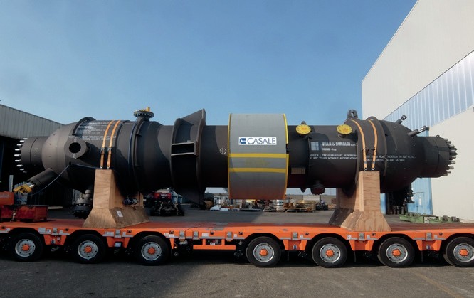
Casale, as technology licensor, brings added value to any project for revamping or grass root urea production plants thanks to its competence developed over several decades and to its capability to bring together technology and mechanical engineering competence in a single project. Casale has improved and consolidated process schemes, materials of construction and the mechanical design approach to drive down the consumption of medium pressure steam in urea plants.
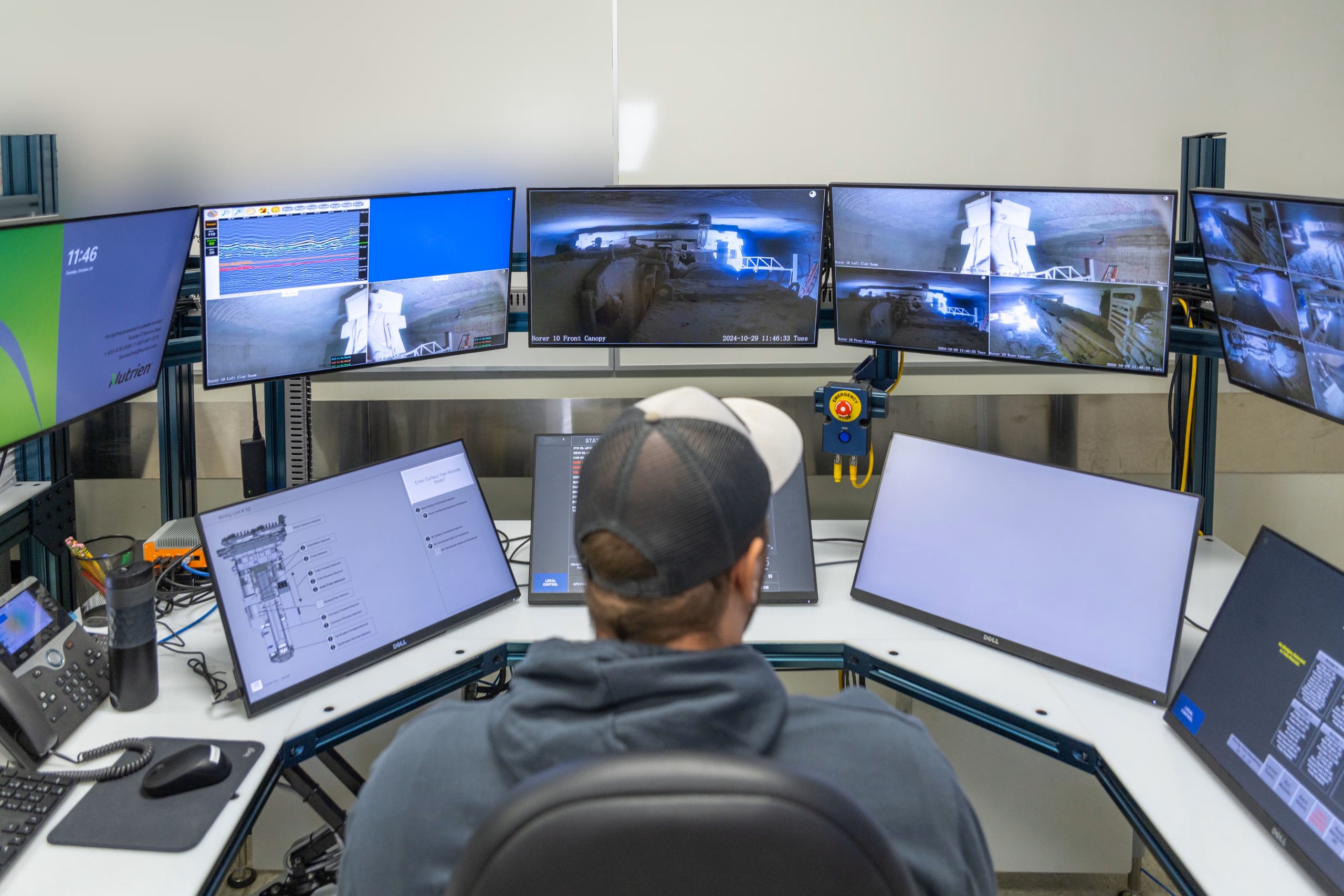
Production plants can also benefit from Casale’s valuable experience in process operation through its wide range of digital services aimed at remote monitoring and optimisation.
A leap forward in equipment reliability has been brought about by the introduction of new super duplex steel. Super duplex materials are characterised by a higher content of chromium and lower content of nickel compared to the super austenitic steels previously employed. Such chemistry allows for ferritic and austenitic layers to be bonded into a “sandwich” structure exhibiting superior corrosion resistance properties.
In joint cooperation with Tubacex, Casale has developed and extensively tested Uremium29, a super duplex material for HP urea service.
The introduction of Uremium29 and the latest approach to equipment design allows not only new grass roots installations, but also vintage small-to-medium urea plants to remain competitive after decades of service. The goal of most owners of vintage urea plant is to prolong the lifetime of their facilities with focused maintenance interventions, end-oflife equipment replacement and at the same time small- to medium-scale debottleneck revamping to achieve opex figures in line with the most modern grass roots installations.
In this context it is understood that the industrial urea community is looking at reliability from a different perspective, i.e. plant performance should be supported by both mechanical and process reliability, otherwise an efficient, but costly, modern stripping plant can experience a more drastic erosion of its gross margin for any unexpected mechanical failure, prolonged downtime or slowdown of production than a vintage less efficient plant.
Uremium29 − reliable efficiency
Uremium29 is an austenitic-ferritic steel with high chromium and low nickel contents in accordance with requirements of ASTM UNS S32906 and ASME Code Case 2295.
Since its first delivery to the market, in 2016, Casale has accrued a number of Uremium29 orders for new critical HP equipment. The material reliability and suitability was broadly tested for an extensive range of urea process conditions in strict lab tests and in plants before being released to the market. Casale was determined to exploit its superior mechanical and chemical properties to boost the life expectancy of critical urea equipment without compromising on plant efficiency. Uremium29 find its natural application in all parts in contact with process fluids of the synthesis section of stripping plants. In addition to critical equipment, it is also highly suitable for piping, fittings, control valves and critical components of process instrumentation.
Besides these virtues, the enhanced re-passivation capacity of Uremium29 has an immediate impact on the efficiency of urea synthesis without compromising on plant reliability. In CO2 stripping plants for example, where parts in contact with the process fluids of the HP stripper are made of traditional 310 MoLN steel, the required oxygen fraction in the CO2 feed ranges from 0.6 to 0.8 vol-% which has a detrimental effect on conversion in the urea reactor. Use of super-duplex such as Uremium29 allows a drastic reduction of oxygen for passivation, down to 0.3 vol-%, which typically improves conversion with consequent reduction of MP steam consumption by 2.0 to 3.0%. Additionally, the increased resistance to corrosion, and the superior mechanical strength, allows thinner tubes to be used. Thinner tubes reduce the overall weight of the item which becomes extremely useful when replacing existing vintage strippers as it makes it possible to increase the number of tubes without the need for reinforcement of the support structure and foundations. Tubes with larger internal diameters handle an increased maximum load per tube prior onset of flooding. In existing vintage urea plants where the HP stripper is frequently the capacity bottleneck, simply replacing the existing item with modern strippers equipped with Uremium29 tubes often creates enough room for a moderate plant capacity increase. This concept also applies to other critical items in urea stripping plants; for example, replacing a traditional 310 MoLN HP carbamate condenser with a new one equipped with Uremium29 thinner tubes allows for a larger surface area at comparable equipment weight. The new HP carbamate condenser would generate LP steam at higher pressure than the replaced item, therefore opening up the possibility to debottleneck downstream equipment and increase plant throughput.
Uremium29 is also ideally suited for application in process locations where the presence of two-phase liquid-gas flow and high fluid velocity may activate erosion induced corrosion phenomena. It is a useful choice for any equipment internal, two-phase flow piping and especially for the design of the synthesis letdown valves, which need to withstand heavy duty service for many years.
The use of Uremium29 as material of construction for HP strippers is not limited to CO2 stripping; Casale also applies Uremium29 to self-stripping technology which traditionally relies on zirconium, titanium or bimetallic (25Cr.22Ni.2Mo + zircornium) tubes to withstand the high temperature at the stripper bottom. In the most typical process embodiment where a bimetallic stripper is employed, air compressors are provided to satisfy the passivation needs and protect the stainless steel internals, liners and weld overlays against corrosion. The most critical location is actually the stripper outlet, where the average working temperature reaches 204-205°C.
Casale’s philosophy for self-stripping technology foresees fully exploiting the potential of Uremium29 by replacing the bimetallic equipment used in combination with the improved NH3 stripping process configuration. This solution consists of installing a level in the reactor top, typically by replacing the reactor cover. In this way, the vapour phase at the reactor outlet, which still contains oxygen, is separated from the liquid and is driven by a new line up to the new Uremium29 stripper bottom to provide oxygen for passivation purposes. In this way, passivation air compressors, which are highly demanding in terms of maintenance and are typically a source for oil entrainment into the process, can be idled. The overall pressure of inerts in the synthesis loop and ammonia recovery sections of the urea plant is also reduced providing a great benefit in terms of condensation and ammonia capture capacity.
Casale operational assistance
The operation of a urea process is a very complex task. The complexity arises from the intricate interaction between participant chemicals and from the need to manipulate a large set of variables to reach production targets, while maintaining optimum efficiency in terms of consumption and emission figures.
The close relationship between process operation and mechanical reliability actually adds an additional element to the complex operation of chemical plants. Often, plants are highly stressed by the operating conditions which are pushed to the limit to maintain profits. This is particularly true for old plants whose mechanical reliability and related performance must be carefully monitored. Therefore, it is of extreme importance to develop maintenance programs aimed at improving reliability. The operational data becomes a fundamental part of a more extensive analysis that not only supports the diagnostics of failures but also helps to understand the root causes during mechanical inspections.
To help plant operations to achieve and maintain the best efficiency, support maintenance and further improve reliability, Casale has created a portfolio of digital products that take full advantage of the existing plant data infrastructure:
- Casale Remote Engineering Service (CARES), providing valuable support aimed at achieving the customer’s production targets, improving process reliability and supporting mechanical inspections;
- Casale Operator Training System (OTS), to improve the confidence and knowledge of operational teams, because people are the most valuable asset, the internal factor in driving the plant close to the optimum efficiency;
- Casale Model Predictive Control (MPC), a trusted “auto-pilot”, embedding process knowledge to keep the plant cruising at its best efficiency, every moment, every day;
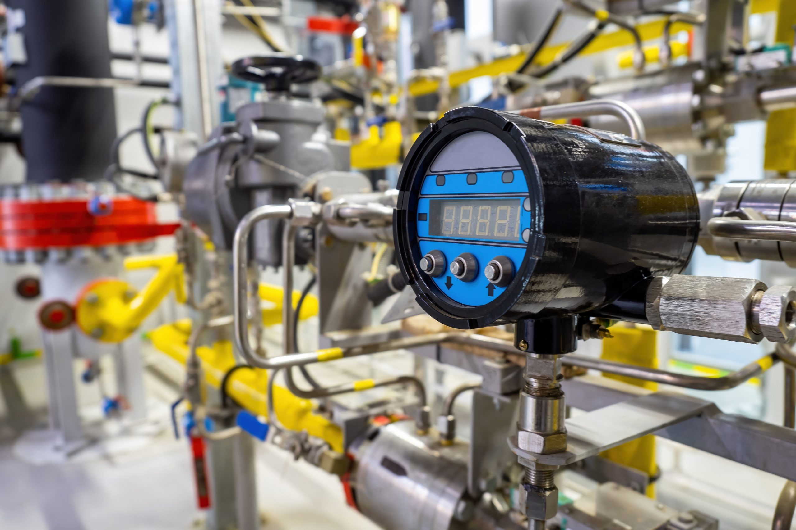
- Casale smart instrumentation providing reliable tools to assist operations: Advanced URea Online Raman Analyser (or AURORA), tunable diode laser, refractive index meter, HP urea service guided wave radar level, etc.
THYSSENKRUPP INDUSTRIAL SOLUTIONS
Higher operating stability with a self-regulating pump
One of the well-known challenges in operating a urea plant is to keep the biuret formation to a minimum in order to avoid off-specification product. Biuret formation is an unwanted but inevitable side reaction of two urea molecules polymerising with elimination of ammonia. The formation is accelerated by three factors: low ammonia concentrations, high temperatures and high residence times. There are a few locations in every urea plant, where all these factors occur at the same time. In this article the focus is on the outlet of the evaporation section and the melt transfer line to the granulation unit.
In order to transfer the urea melt leaving the evaporation section to the granulation unit and to ensure the required supply pressure for the granulator spray nozzles, a dedicated pump is required.
Considering that the evaporation section is operated at vacuum conditions and the melt leaving the evaporator is boiling, the NPSH (net positive suction head) for that transfer pump has to be accordingly high. A common value is 3 m. But having a suction head of approximately 3 m in order to avoid cavitation, consequently leads to a higher residence time of the urea melt in the pump suction line and thus to increased biuret formation.
To avoid this scenario, thyssenkrupp Industrial Solutions (tkIS) optionally equips newly built plants with a special self-regulating pump. Compared to a conventional centrifugal pump, the self-regulating pump is independent of the intake rate, i.e. the pump capacity always corresponds to the intake rate resulting in a required NPSH of approximately 0 m. Consequently, the required suction head and therefore the residence time of the melt are decreased to a minimum, leading to less biuret formation and avoiding plant trips due to a loss of level.
A fertilizer complex consisting of an ammonia and a urea plant normally runs smoothly without significant capacity changes. But, in case the complex consists of more units, e.g. urea synthesis, urea granulation, diesel exhaust fluid unit, UAN, which the urea plant has to supply with urea solution or melt, the evaporation unit of the urea synthesis and the granulation plant can suffer from an unstable supply of urea solution and melt. In these cases, the operator has to adapt the load to the evaporation section and consequently the transfer pump capacity accordingly. Especially when the evaporation feed has to be reduced, care has to be taken in cases where a conventional centrifugal pump is used. Reducing the evaporation feed can easily initiate the dry run protection of the pump in the suction line, resulting in tripping of the downstream granulation unit. However, if a self-regulating pump is used, that scenario will not happen. Due to the self-regulating character of the pump, the capacity will adapt according to the intake rate without causing a trip of the pump and the downstream process unit. Thus, capacity fluctuations can be easily handled by this type of pump, facilitating the plant operator’s work and reducing the risk of tripping downstream units.
Another advantage of the self-regulating pump is the elimination of layout constraints for the outlet of the evaporation section. When using a conventional centrifugal pump, a required suction head has to be maintained. Depending on the plant layout, the line between the outlet of the evaporator and the suction flange of the pump can be quite long, increasing the melt’s residence time and thus promoting biuret formation. A self-regulating pump can be located directly below the evaporator outlet, since no specific suction head is required. Only the overall height of the pump frame and the required head space has to be considered. Fig. 1 shows a typical pump setup. It is clearly visible how close the pump can be placed to the evaporator, which can be seen in the background.
Over the past years tkIS has gained a lot of good experience using the self-regulating pump with respect to efficiency and reliability. Furthermore, the plant layout has improved specifically at this challenging location. The self-regulating pump provides security for a stable operation, especially for the downstream granulation unit. tkIS holds the patent rights to install a self-regulating pump at this location. The self-regulating pump can be installed for grass-roots plants as well as during revamping.
SAIPEM
A proven approach to achieving better equipment life
While good design is the starting point for long-lasting equipment, it is not the sole answer to the problem of ensuring reliability of urea plants, according to the experience of Saipem, as licensor and EPC contractor of the Snamprogetti™ Urea Technology. Care during the construction and throughout the whole lifetime of the equipment is also essential.
Saipem’s main focus of its proprietary urea technology centres on the high pressure equipment due to the criticality of their operating and design conditions.
Saipem draws upon its experience in plant and equipment design spanning a wide spectrum of fields, ranging from green technologies to the oil and gas industry, to find the most appropriate solutions for the optimisation and improvement of equipment design.
By establishing close and enduring relationships with manufacturers, equipment can be designed with the knowledge of any associated construction issues, ensuring that the proposed solutions are technically viable, thus avoiding unexpected, expensive and time-consuming reworks aimed at finding alternative solutions which, in the rush to meet the project schedule, may not be the optimal ones.
It is these experiences and bonds with manufacturers that are the basis for the continuous development of the equipment design, as well as, for the definition of criteria, the renowned confidential and proprietary Saipem’s “510 & 516” series of specifications. These criteria consist of a collection of requirements regarding materials, methods of construction, examinations and inspections during manufacturing that are periodically updated based on the feedback from manufacturers and operating plants to ensure and to improve the quality of the equipment. The presence of Saipem’s quality inspectors during the main steps of construction of its equipment, either in the manufacturer’s workshop or, in case of constraints (as experienced during the recent pandemic) remotely, ensures that all fabrication steps are monitored, providing the smooth and timely manufacture of equipment according to Saipem’s design requirements and criteria.
Once equipment is installed, Saipem is proud to assist end-users by offering its post-sales assistance, which covers a wide range of services with the target of monitoring the status of the equipment, ensuring (if not prolonging) its expected life time and boosting its performance. In this way Saipem has acquired and developed a deep knowhow for all the different pieces of equipment, specialising in performing the inspections, understanding the best approaches to attend the required maintenance and, last but not least, getting a feeling on how to intervene if features of equipment design require improvement.
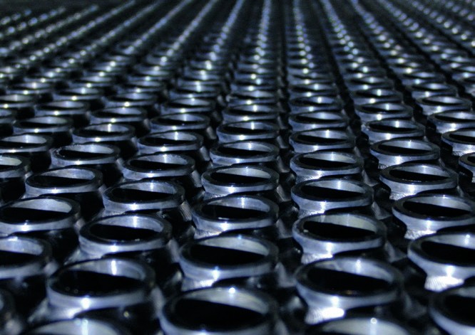
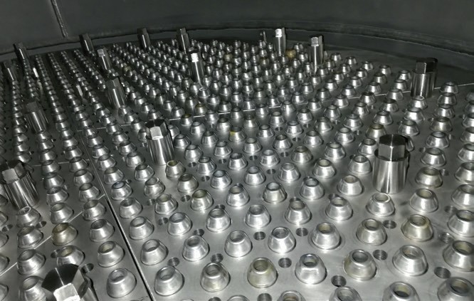
A demonstration of the benefits of this approach is the development of the design of the ferrules of the urea stripper. Ferrules are the distribution devices for the urea solution, installed over the head of the tubes, that generate a falling film flow along the tubes of the heat exchangers (in this case the urea stripper) thus providing optimal heat transfer and efficient decomposition of the carbamate and consequent release of the vapours.
By performing the inspections on different plants and relevant strippers, it has been noticed that the portion of the bimetallic tubes heads from where the zirconium was removed was more prone, long term, to corrosion issues; corrosion was due to 25/22/2 Cr/Ni/Mo material (in proximity of the weld) being directly exposed to the process fluid and to the higher temperatures of the tube-sheet.
After a joint discussion among process and mechanical engineers and quality experts, the design of the head of the tubes was modified by increasing the length of the protrusion of the tube ends over the tube-sheet to allow for maintaining the terminal zirconium and consequently avoiding, over long periods, the risk of corrosion on 25/22/2 Cr/Ni/Mo tubes. The proposed design was then presented to the stripper qualified manufacturers to check whether from a construction viewpoint the studied improvements were feasible and, in particular, to what extent. Manufacturers confirmed the weldability of the tubes to the tube-sheet and defined limits for the length of the tube protrusions.
The design was also updated by switching from internal to external ferrules, as it was no longer possible to maintain an internal ferrule without reducing the passage area inside the tubes. The ferrules were also subject to other modifications aimed at improving the sealing over the tubes and their stability; based on feedback from manufacturers and end-users, the design of the hold-down grid for the ferrules was also updated to improve its duty and to facilitate its installation.
Another aspect, which is a high priority for end-users worldwide, is the importance of inspections for proper maintenance of the equipment: a well scheduled inspection and maintenance plan for the equipment is of fundamental importance to meet the current practice of having turn-arounds every three or even four years.
Saipem recommends that the maintenance of the HP equipment should be performed by specialised and qualified companies (including, but not limited to, the equipment manufacturers) so that the quality of the repair activities is ensured with a beneficial effect on equipment life. By hiring specialised contractors with a deep knowledge of the equipment to attend the maintenance, the risk of catastrophic failure due to a repair activity not being performed properly is minimised.
It is important to note that equipment failure can have dramatic consequences, firstly from a safety viewpoint considering the operating conditions (temperature and pressure) and the toxicity of the fluids circulating in the equipment and, secondly, from an economic point of view considering the loss of production while the equipment is repaired (even if temporary) or replaced.
Maintenance is of particular importance for equipment close to the expected end of life where each small repair and maintenance activity can lead to important extensions of equipment life. The lack of appropriate inspection and maintenance is what has led to the failure of some older reactors in recent years that were close to the end of their expected life.
During the investigation into the causes leading to failures, Saipem was able to identify a series of common causes, different in nature, but all leading to the final failure of the reactors.
One of the main causes was the lack of appropriate inspections and data collection. Apart from the frequency and thoroughness of the inspections, it is important that proper and reliable measurements (e.g., for thickness) are taken using the correct tools, which should be properly handled and calibrated.
Another cause was the selection of a non-specialised contractor to attend the repair activity which, as already discussed, is a risk. It is of utmost importance that the contractor selected by the end-user, while performing the repair job, is fully aware of the design and characteristics of the equipment and of the consequences of a poorly executed repair job. It was also noted that proper supervision of the repair activities and the correct processing of the errors that occurred during the repair activity could have avoided the failures. For these reasons Saipem, as urea licensor, provides assistance and support services for the review of the procedures, qualifications, and drawings to be used during maintenance activities and invites all end-users to take advantage of such services with the aim of minimising the occurrence of issues during the execution of the activities they carry out themselves.
It is worth saying that, while it is the course of action by inspection and maintenance staff, being actively involved during the turnarounds, that probably has the most impact on prolonging the life of equipment, the operation team also has a share of the responsibility. The plant operators working in the plant every day are in fact best placed to be the first to detect possible leakages by performing a correct inspection of the weep holes. Weep holes are the mechanical expedients with the function to detect any leak from the lining welds (the welds performed between the different lining sectors) by providing passage of the leak across the pressure retaining wall of the equipment, via dedicated grooving and tubing, thus saving the equipment from carbon steel corrosion issues. The inspection of weep holes must be performed regularly, on a daily basis, taking care to also periodically verify that the weep hole circuits are free from plugs and, if any plug is found, to carefully remove them. Considering the total number of weep holes and their location on the plant, many end-users opt for an automatic leak detection system which ensures continuous monitoring, sparing the operators the time required to check the weep hole, allowing them to attend other activities providing better time management.
Various automatic leak detection systems are available on the market, proposed by different vendors and having different operating schemes and working principles (e.g., operating under vacuum or pressurised conditions). Saipem advocates the use of automatic leak detection systems provided that they are designed considering the peculiarities of the urea environment with particular attention to avoid the formation of plugs and to ensure that leaks are promptly detected. Saipem has not developed its own proprietary solution, preferring instead to rely on a proven and qualified solution already available on the market. This solution, based on the vacuum operating principle, has been jointly developed and commercialised by renowned and esteemed companies and it was technically approved by Saipem, after a thoughtful review involving both its capabilities as licensor of Snamprogetti™ urea technology and as EPC contractor.
To conclude, Saipem encourages end-users to exploit the scheduled maintenance activities and/or the replacement of equipment to boost the performances of their plant(s). Replacing equipment that has reached end of life with the latest updated design of equipment can also provide an opportunity to debottleneck the plant e.g. by increasing the exchanger surfaces or by increasing the reaction volumes. Variations to exchanger surfaces and volumes may, however, be limited by structural constraints. In fact, a bigger piece of equipment may not have sufficient space due to existing structures, piping and other equipment or it may require modifications to the structures or foundations due to the increased weight.
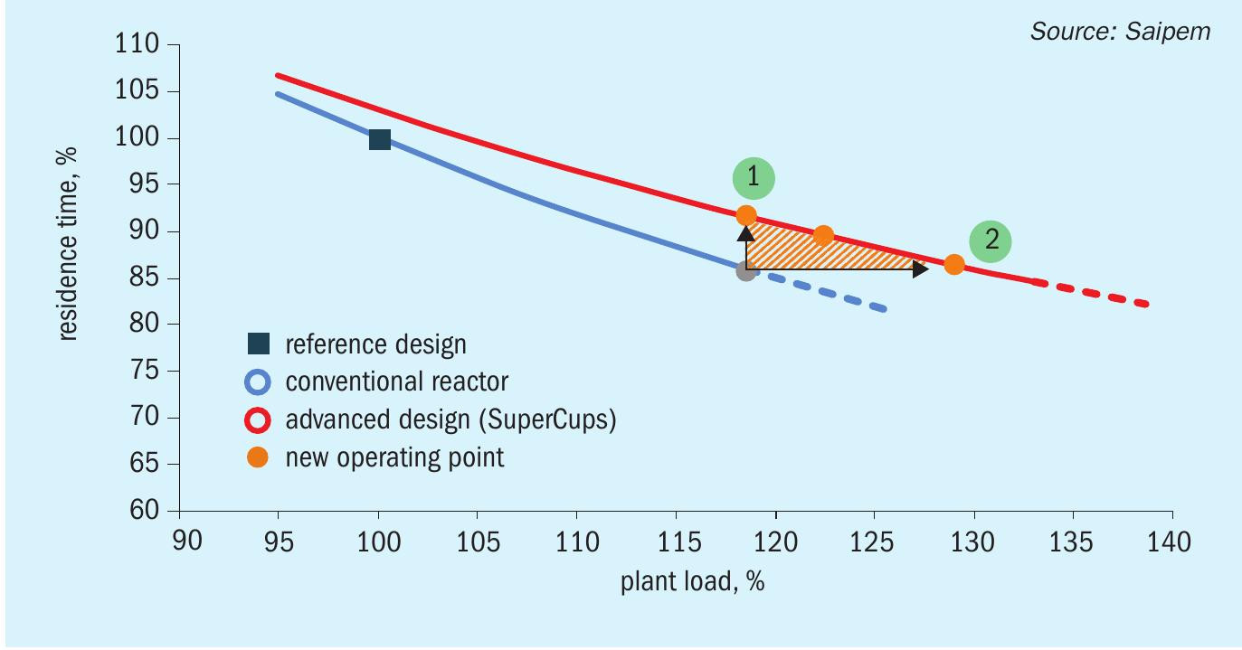
A solution to this for both existing reactors and new replacements is to install SuperCups. By means of their triple fluid-dynamic effect, SuperCups can easily boost the performance of an existing plant by promoting contact of the reagents and enhancing reactor conversion. It has been demonstrated that the characteristic “plant load vs residence time” curve of a reactor installed with SuperCups is higher than one with sieve trays (Fig. 1). By switching from sieve trays to Super-Cups, the residence time of the reactor for a fixed capacity is increased allowing higher conversions rates to be achieved. Higher conversion rates in the reactor mean lower decomposition (primarily in the urea stripper), condensation (e.g., in the carbamate condenser) and recycling loads to the downstream equipment, enabling the plant to reduce its power consumption, and therefore its carbon footprint, or to increase its production without further and more expensive interventions.
TOYO
Technologies for improved reliability and safety of urea plants
Toyo Engineering Corporation (TOYO), a global leading engineering contractor and urea process licensor, has developed various technologies to improve the reliability and safety of urea plants and increase efficiency. In this article, TOYO introduces its innovative technology line-up:
- super duplex stainless steel (DP28W™ );
- leak detection system; l AOCM™ (Advanced Online Corrosion Monitoring);
- IDCS™ (Image Diagnosis for Corrosion Screening).
Amongst others, AOCM™ and IDCS™ are recent introductions which TOYO believes will enhance maintenance activities for the critical equipment in urea plants.
DP28W™
TOYO has more than 40 years of experience in applying duplex stainless steels to urea plants. The most significant advantage of duplex stainless steel is its excellent corrosion resistance in urea-carbamate solution, which enhances the reliability and safety of equipment, and reduces the amount of passivation air required. Responding to industry demand, TOYO and Nippon Steel Corporation (NSC, formerly Sumitomo Metal Ind., Ltd) developed an advanced duplex stainless steel for urea plants, named DP28W™ , which has greatly improved the safety and economy of the urea plant over its lifecycle.
Features of DP28W™
DP28W™ has outstanding features in terms of alloying design, mechanical properties and corrosion resistance.
Alloying design
DP28W™ (28Cr-8Ni-1Mo-2W) shows excellent corrosion resistance, not only in the base metal, but also in the heat-affected zone (HAZ). A combination of the high chromium content, the addition of tungsten and a well-balanced ferrite/austenite structure have achieved excellent corrosion resistance. The molybdenum content is intentionally reduced to keep good corrosion resistance in the HAZ. The addition of tungsten compensates for the adverse effect on corrosion resistance in the base metal by reduced molybdenum. Optimisation of the chemical composition has been done by multiple linear regression analysis with the data obtained through tests in a pilot plant and commercial plants.
Mechanical properties
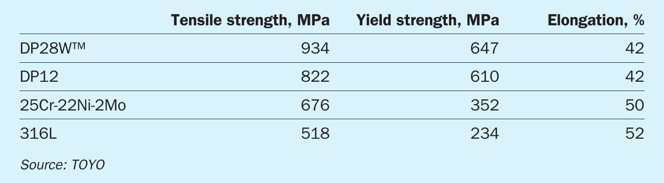
DP28W™ has remarkable mechanical properties. Table 1 shows an example of tensile test results for DP28W™ compared to other stainless steels. The table indicates that DP28W™ has high mechanical strength compared to austenitic stainless steels such as 25Cr-22Ni-2Mo and 316L, providing a great advantage for the mechanical design of equipment.
Corrosion resistance
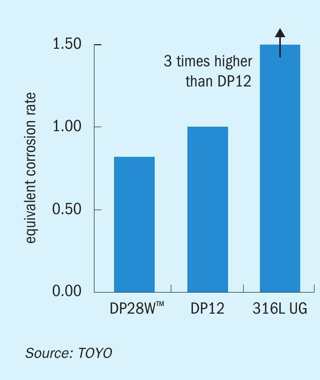
Corrosion resistance of DP28W™ to urea-carbamate solution has been proven in commercial plants. An example of immersion test results in a urea stripper is shown in Fig. 1. As shown, 316L UG corrodes at a high rate because it cannot maintain the passivation film due to severe corrosive conditions in the stripper. By contrast, DP28W™ shows excellent corrosion resistance, and also provides a lower corrosion rate than DP12.
Advantages of DP28W™ over the plant lifecycle
DP28W™ provides a number of great advantages which contribute to the safety and economy of the urea plant:
Enhanced reliability and maintainability of equipment
The expected corrosion rate of DP28W™ is lower than existing materials. The corrosion resistance in the HAZ and weld metal is greatly improved compared to conventional duplex stainless steels. These positive features provide the following advantages over the plant lifecycle:
- prolongs the life of components exposed to urea-carbamate solution;
- decreases maintenance frequency;
- reduces the risk of active corrosion.
Decrease of passivation air
DP28W™ is easily passivated with less dissolved oxygen in urea-carbamate solution. It suggests that the passivation air, which restricts operational efficiency due to lower conversion in the synthesis section and ammonia loss in the recycle section, etc. can be positively reduced.
Design allowance
DP28W™ has a higher allowable stress value and stress intensity value than austenitic stainless steels and conventional duplex stainless steels. This high mechanical strength provides a larger design allowance.
Experience
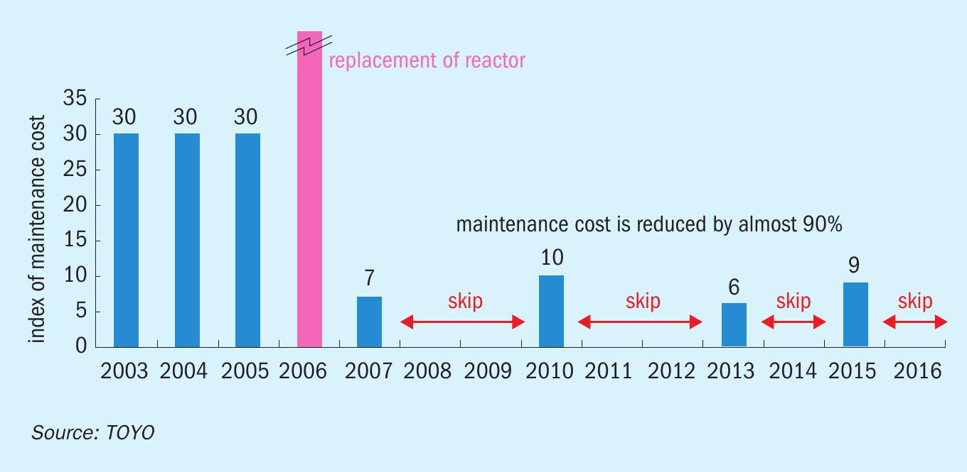
DP28W™ has been applied to TOYO urea plants since the middle of the 2000s and has shown excellent performance to date. For example, one owner replaced its existing titanium-lined urea reactor, in the total recycle process, with a new reactor lined with DP28W™ . The owner had clear intentions to operate the new reactor under the same operating conditions as the existing reactor (200 bar, 200°C). The operating condition was severe as titanium requires little passivation air even at high temperature. Nevertheless, it is notable that the actual corrosion rate of DP28W™ has been far lower than titanium. The new reactor fabricated with DP28W™ has been operating successfully since it was put into operation in 2006 and the owner has reduced its maintenance cost drastically by 90% as shown in Fig. 2. The maintenance activity during each turnaround has been mainly visual inspection only and there have been no major repairs caused by the material.
Leak detection system
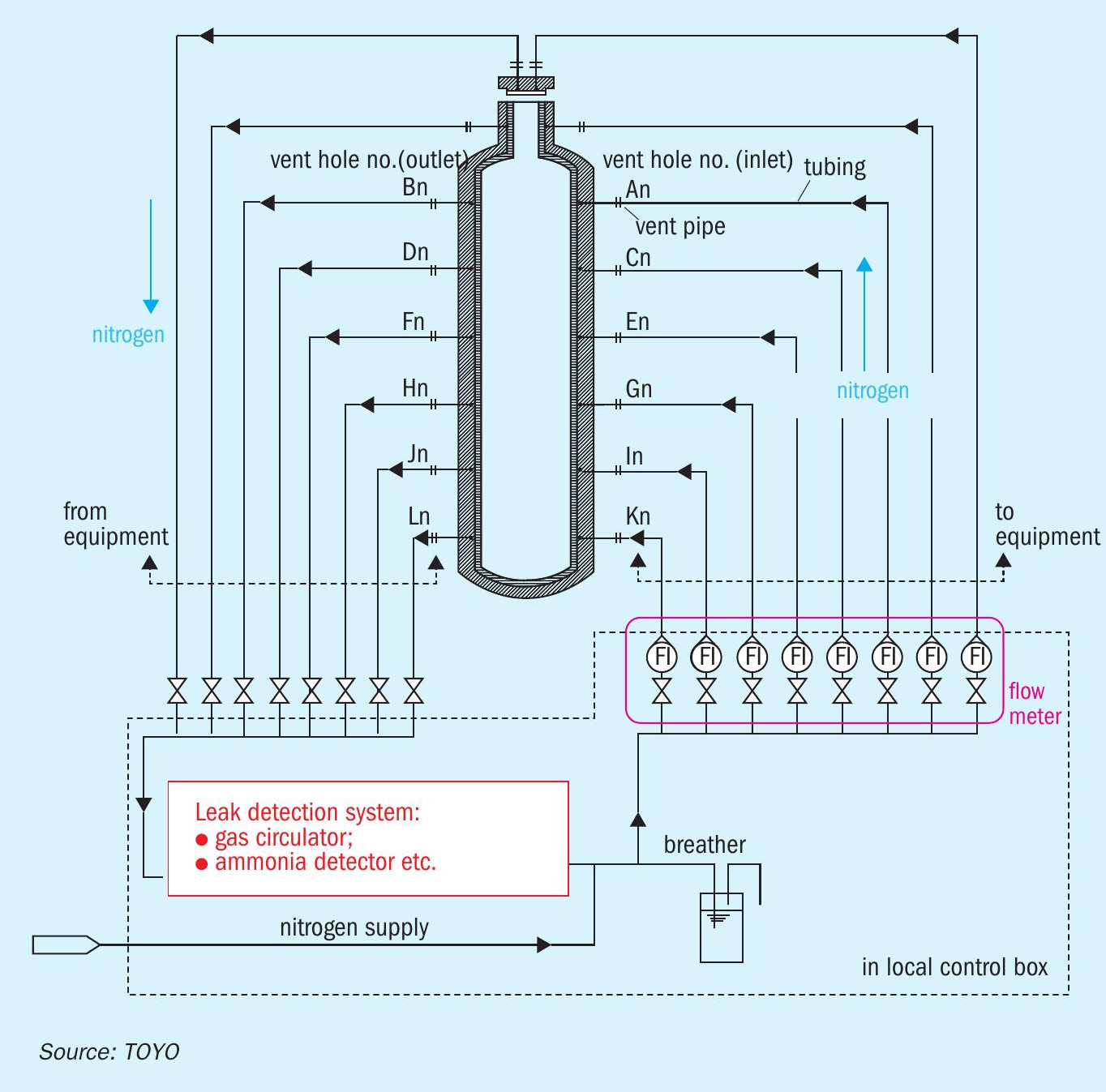
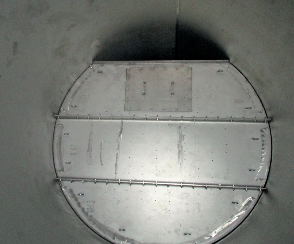
The internal wall of the high-pressure equipment in the urea plant is in contact with corrosive fluid and is lined by a proper corrosion-resistant metal plate. In the event that this lining plate has a leakage, it leads to damage to the pressure holding shell made of carbon steel.
TOYO has developed an on-line leak detection system by detecting ammonia leaking in circulating nitrogen gas between the lining plate and pressure holding shell (See Fig. 3). This system has the advantage of being able to detect tiny amounts of leakage and to identify the location of the defect before the damage becomes severe.
The system also contributes to making maintenance work easy and simple, and increases the reliability of the urea plant.
AOCM™ (advanced online corrosion monitoring)
Corrosion monitoring of high-pressure equipment and piping in the urea synthesis loop on a real-time basis is beneficial for plant owners not only in establishing optimised inspection plans, but also enabling reliable operation. Assessing a real-time condition of stainless steels exposed to ammonium carbamate is particularly challenging. AOCM™ is a solution that can predict the condition of the equipment and piping.
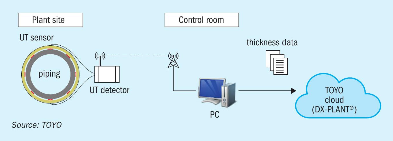
Fig. 4 shows the AOCM™ system applied to synthesis piping. Ultrasonic testing (UT) sensors installed in the piping measure the corrosion rate on a real-time basis.
AOCM™ application to ACES21®
TOYO has developed AOCM™ to apply to ACES21® , TOYO’s urea synthesis technology (see Fig. 5).
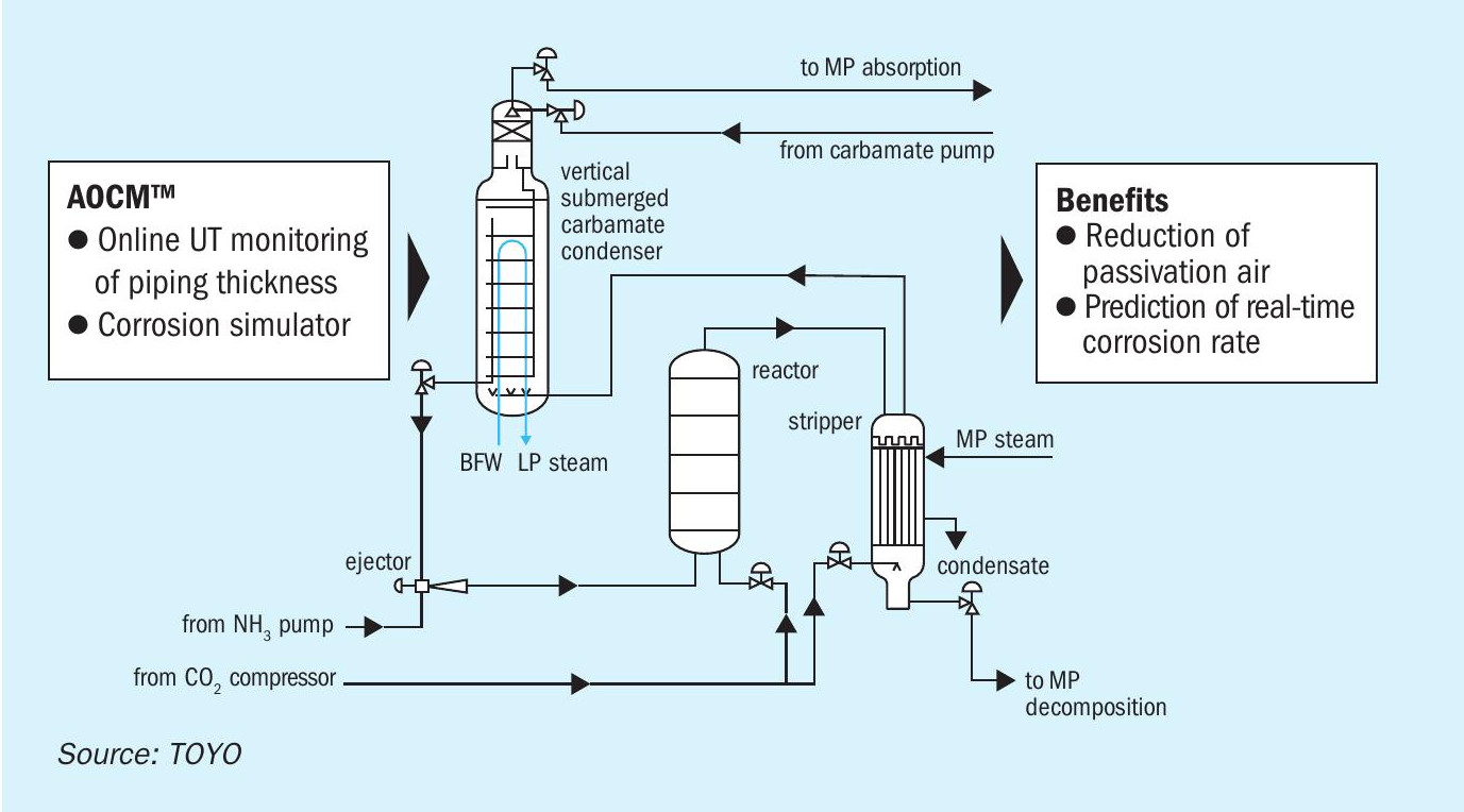
Piping
AOCM™ is applied to the piping in the ACES21® synthesis section, where its main function is to monitor the corrosion rate of the piping on a real-time basis. UT sensors are installed directly on the piping in various locations. The piping thickness measured by UT sensors is transferred to DX-PLANT® wirelessly on a real-time basis; this allows plant owners to monitor corrosion rates of individual piping with reference to operational parameters such as temperatures in real time.
Equipment
The corrosion simulator has been developed by TOYO based on empirical data obtained from immersion tests and is utilised for on-line corrosion monitoring of high-pressure equipment, since the installation of UT sensors in such high-pressure equipment is physically impractical. TOYO’s corrosion simulator predicts the corrosion rates of each type of stainless steel for both the equipment and the piping in the urea synthesis section using operating temperature and oxygen concentration in CO2 . As there is a certain correlation between the corrosion rates of the equipment and the piping, AOCM™ compares the corrosion rates obtained by the corrosion simulator and the UT sensors to provide a more accurate corrosion rate of the equipment.
Benefits of AOCM™ for plant owners
Since the urea synthesis section is a highly corrosive environment, passivation air needs to be introduced for corrosion prevention. Optimisation of the amount of passivation air will bring considerable benefits for plant owners, for example, increasing the urea synthesis rate or saving energy consumption, leading to opex reduction. While insufficient passivation air will cause severe metal loss due to active corrosion, AOCM™ ensures that passivation air can be reduced by corrosion monitoring on a real-time basis without the risk of active corrosion. Furthermore, plant owners can optimise shutdown maintenance activities and shutdown schedule (interval, period, timing) in advance by using the accurate information on corrosion rates.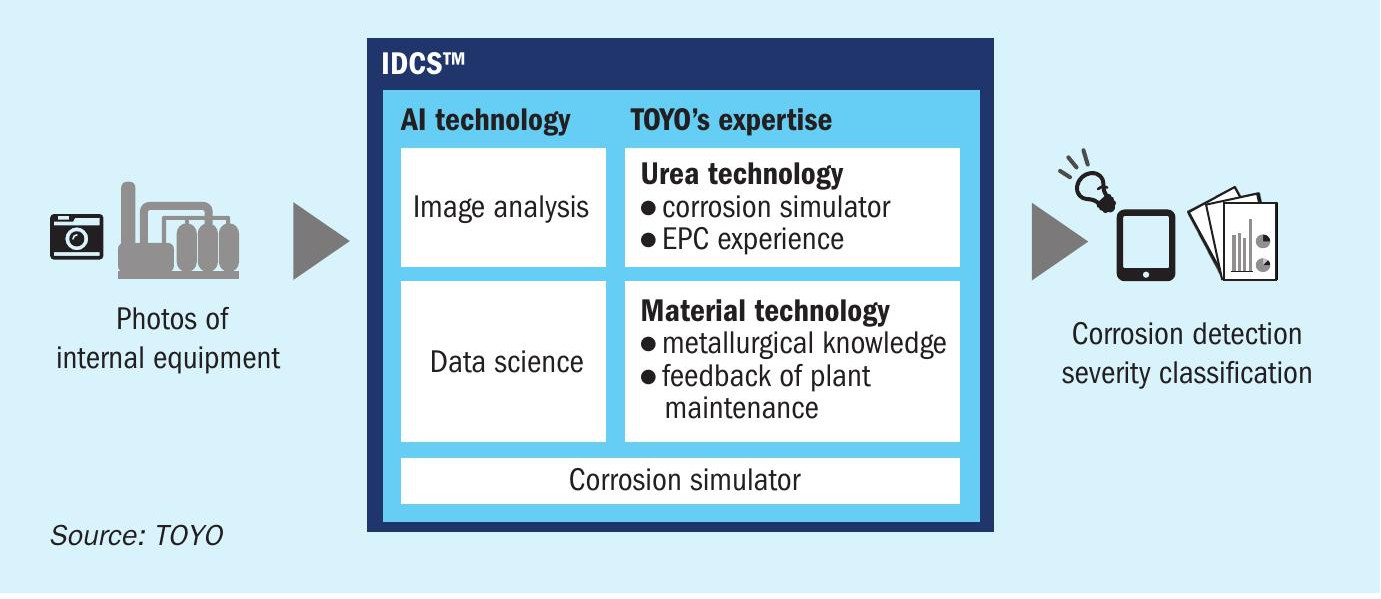
IDCS™ (image diagnosis for corrosion screening)
TOYO’s image diagnosis for corrosion screening (IDCS™ ) system is a new way to screen and detect corrosion of equipment internals during plant maintenance. This system utilises image analysis technology by artificial intelligence (AI) and enables efficient inspection for equipment during plant maintenance. Fig. 6 shows an outline of IDCS™ . The system is configured with a combination of AI technologies, such as image analysis, data science, a corrosion simulator and TOYO’s expertise, enabling a high speed and reliable analysis. IDCS™ facilitates corrosion detection classification of the severity for equipment internals using image data of the target equipment, as described in the following section.
The advantages of IDCS™ are:
- Time saving, accurate, and less person-dependent visual inspection during plant maintenance:
– IDCS™ provides greater efficiency compared to conventional inspection in which inspectors spend a long time on a ‘one-by-one’ visual inspection and the quality of the inspection tends to be highly dependent on the inspectors’ skills and time available.
- Dependable and easier estimation of timing for repair or replacement of equipment
– By applying IDCS™ periodically on the plant inspection and accumulating the historical data obtained, condition-based maintenance with reduced opex can be realised.
Work flow of new methodology of plant maintenance with IDCS™
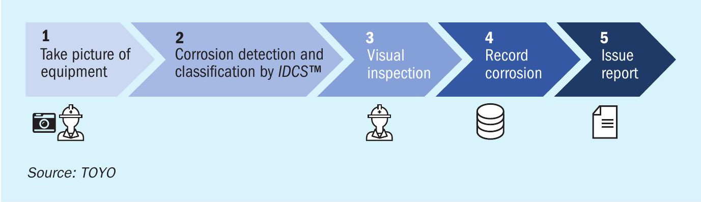
Fig. 7 shows a work flow of the new methodology of inspection utilising IDCS™ during plant maintenance. The procedure includes the following steps:
- take pictures of equipment internals and import them to IDCS™ ;
- IDCS™ detects corrosion and classifies corrosion severity into 4 levels by image analysis of the pictures;
- inspection personnel perform visual inspection mainly where the system detected corrosion;
- automatically record the corrosion details (location and severity of corrosion); automatically issue reports including the corrosion details.
IDCS™ verification test
At the development phase, TOYO conducted a verification test of IDCS™ for the stripper in the urea synthesis section.
The stripper has been operating for over 20 years in some TOYO ACES plants (previous process to the latest ACES21® ) and corrosion by ammonium carbamate has been occasionally observed on the tube-totubesheet (T/TS) welds. Corrosion on the weld HAZ on tube internals was the most inspected point. In addition, conventional visual inspection of thousands of T/TS welds requires highly skilled personnel and takes a long time. Therefore, utilising the sample of the corrosion on tube internals, the verification test was conducted to validate if IDCS™ has the potential to be applied to the actual equipment for time-saving and less person-dependent inspection.
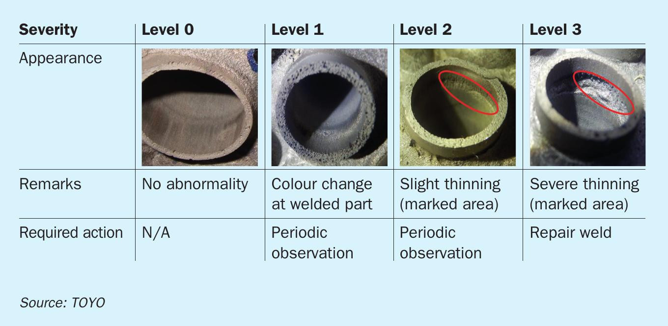
Table 2 shows models of defined corrosion of T/TS weld internals for different levels of severity. At level 0 there is no abnormality. At level 1, colour change is confirmed at the welded part. At level 2 slight thinning is seen on the weld heat affected zone and periodic observation is required for levels 1 and 2. Severe thinning is confirmed on a wide area at level 3. This must be repaired as soon as it is detected.
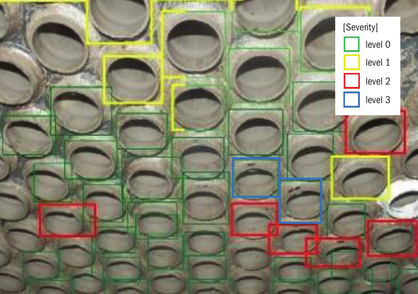
In the first step of the IDCS™ verification test, the IDCS™ had to manually learn hundreds of pictures of reference T/TS welds for each level as training data sets. After this stage had been completed, IDCS™ automatically classified the condition of other T/TS welds according to the four levels of severity and marked the corroded tubes, indicating their level. Fig. 8 shows an example of the output image obtained by IDCS™ . The accuracy of the classification of the corroded T/TS weld internals was higher than 80%. Further improvement to the accuracy is ongoing, aimed at application for actual equipment.
Further development of IDCS™
Considering the results obtained from the verification test, IDCS™ is expected to be applicable to various kinds of plant equipment, regardless of the type of process. To expand the areas of application, some further development is being carried out in the following areas:
- application to weld lines (ex. lining welds, support ring welds);
- application to corrosion cracking, localised corrosion, and weld defects;
- sizing of corrosion and damage;
- identification of the inspected parts (ex. rows and numbers of hex. tubes);
- application to movies recorded in equipment during inspection;
- application to wearable cameras for real time inspection.
STAMICARBON
Boosting reactor performance by high-efficiency trays
In all commercial processes, urea is produced by reacting ammonia and carbon dioxide at elevated temperature and pressure in the urea reactor and can proceed up to chemical equilibrium. Because of the equilibrium nature of the urea reaction, the reaction is preferably done in a plug flow reactor.
This conversion in the urea reactor is mainly determined by the residence time, reactor volume and sufficient contact between the gas phase and the liquid phase.
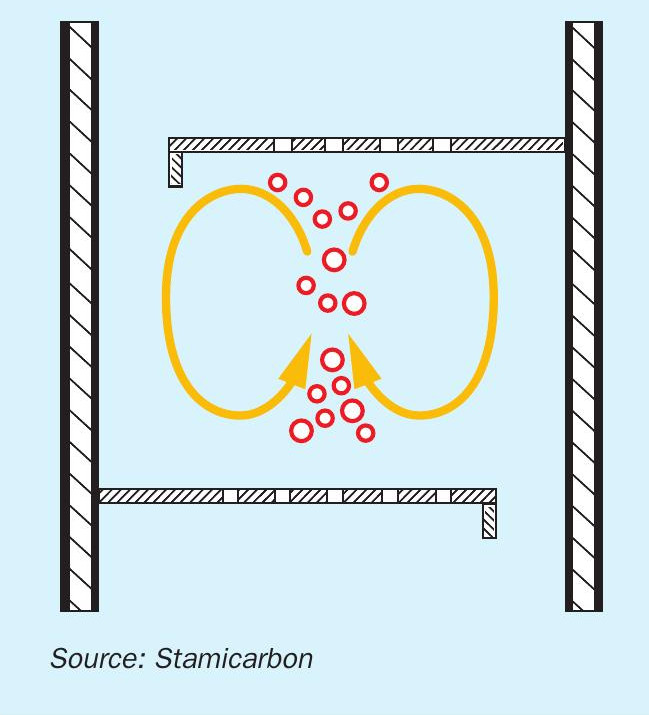
Generally speaking, a plug flow reactor can be achieved by installing numerous continuously stirred tank reactors (CSTR) in series, which can substantially improve the reaction kinetics. Practically this can be realised by installing a certain number of sieve trays along the reactor length, which divide the reactor into several compartments. In this way, the reactor turns into a bubble column with a torus circulation, which improves the contact between the gas and liquid and increases the urea conversion accordingly. The liquid risers are located at a 180° staggered position, to ensure a zigzag flow pattern. This flow pattern will increase the path of the fluids along the reactor and hence increases the residence time and urea conversion (Fig. 1).
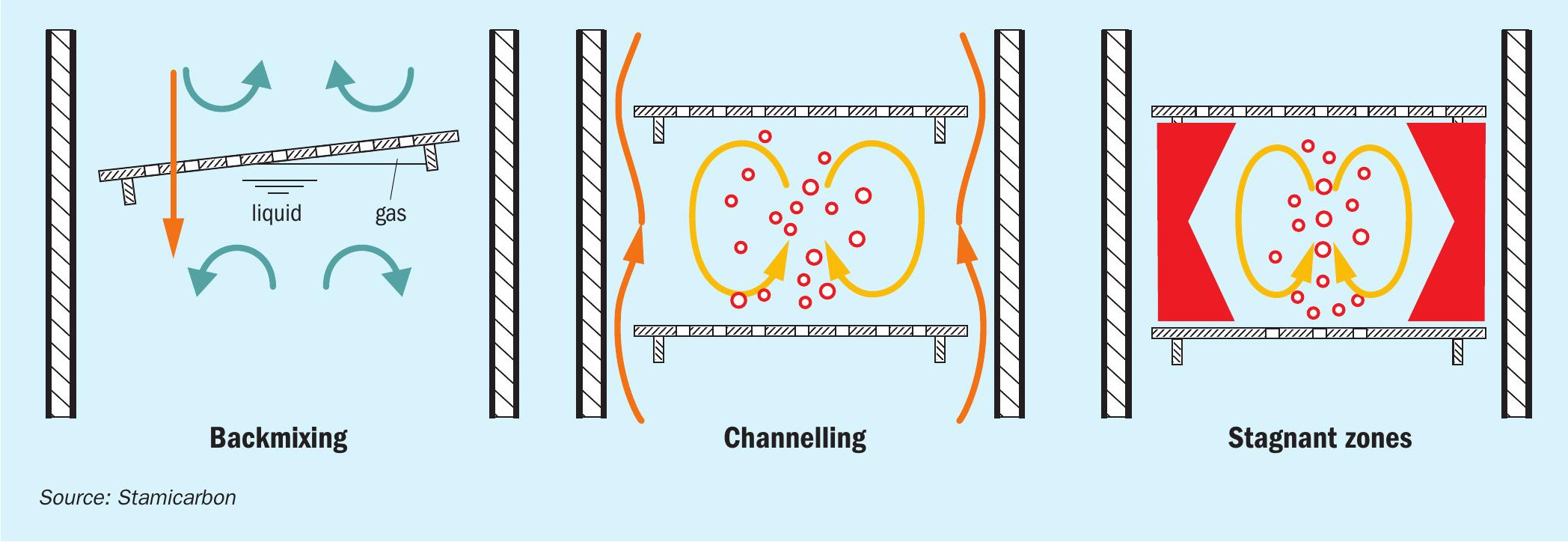
The condensation of ammonia and carbon dioxide causes the quantity of gas to decrease and the temperature to increase, during passage through the reactor. A gas cushion below each tray with a certain height is considered in the design to ensure sufficient seal between the gas and liquid and to avoid the backmixing effect, which reduces the urea conversion in the reactor. The sieve trays in the top of the reactor have fewer holes than those in the bottom. This ensures that also in the top of the reactor, the cushion of gas present under the sieve trays will avoid backmixing and thus maintain the plug flow regime. A plug flow in the reactor is a theoretical assumption as plug flow means there is no backmixing at all. In practice some degree of backmixing is inevitable.
Reactor issues
Stamicarbon, the innovation and licensing company of Maire Tecnimont Group, has developed high-efficiency reactor trays, which have been installed in many urea plants. These trays improve the conversion in the reactor substantially and can solve the common issues which most urea reactors suffer from. These common issues can be summarised as follows:
Backmixing
Backmixing (Fig. 2a) occurs when the liquid accidentally passes through the gas holes. That normally occurs when no or insufficient gas cushion underneath the tray is present. The high efficiency reactor trays as designed by Stamicarbon have sufficient gas cushion to avoid backmixing from occurring. Backmixing can also occur as a result of improper levelling of the tray during the installation which may break or disturb the gas cushion underneath the tray.
Channelling
Channelling (Fig. 2b) normally occurs in reactors with no internals or with conventional trays. Channelling occurs when liquid by-passes compartment without having proper contact with the gas. As a result, low conversion in the reactor is expected. This issue can be excluded in the high efficiency reactor trays with 180° staggered flow path in which a zigzag flow pattern with an optimum gas-liquid contact is ensured.
Stagnant zones
Creating stagnant zones in the reactor (Fig. 2c) can be an issue for the conversion due to the poor contact between the liquid and the gas, which affects the urea conversion consequently. This issue is also solved with the high-efficiency reactor trays by having the zigzag flow pattern, which avoid stagnant zone formation.
General reactor performance
The high-efficiency reactor trays will increase the conversion in the reactor and hence lower the load on the high pressure stripper and high pressure carbamate condenser. This means that the process limits in these equipment items are encountered at a higher plant capacity. The improved reactor conversion is demonstrated by a reduced steam consumption of the high pressure stripper along with a reduced steam production from the high pressure carbamate condenser. Apart from saving energy on the high pressure stripper, the high-efficiency reactor trays may also be used to increase the capacity of the urea plant. The main parameters in the synthesis section are the steam consumption to the high pressure stripper, steam production from the high pressure carbamate condenser, N/C ratio in the reactor overflow, CO2 conversion and top temperature of the reactor.
High-efficiency reactor trays experience
In 2017, Southern Petrochemical Industries Corporation Ltd (SPIC) in India requested that Stamicarbon replace their existing HP reactor with a new one in Safurex® . The old reactor was already at the end of its life time with some major repairs necessary, due to excessive leakages occurred during its operation time. The urea plant was licensed in 1974 and uses TOYO technology with a nameplate capacity of 1,600 t/d. With the old reactor the plant could achieve a capacity up to 2,080 t/d. There were a lot of process inefficiencies due to aging of the equipment, which have had a negative impact on the production and overall performance of the plant.
Reactor features
The old HP reactor was a plug flow reactor with no internals. The outer shell of the reactor was made of carbon steel, while the liner in contact with the process was made of titanium. For the reactor replacement Stamicarbon advised an improved conversion design, including high-efficiency trays and other internals made of Safurex® .
After delivery of the new Safurex® reactor to client’s plant site in 2019, Stamicarbon performed supervision services during installation of the reactor including final inspection. After start-up, Stamicarbon gave process support and training to the operational staff, regarding the features and improved performance figures of the new reactor.
Since the diameter and length and thus the reactor volume of the new reactor were kept the same, it offered Stamicarbon the opportunity to compare and evaluate the performance of the reactor before and after the replacement. Any improvement in the conversion can be attributed to the introduction of the high-efficiency trays with hardly any modifications in the downstream section. A complicating factor was the fact that in this plant there was no sample point downstream of the reactor.
In the SPIC plant, a conventional process is applied in which all the reactants (ammonia, CO2 and carbamate) are added to the reactor. The reactants are present in different phases before being introduced to the reactor. Ammonia and carbamate are in the liquid phase while the CO2 is in the gas/supercritical phase. To achieve proper mixing of these reactants, an inlet gas/liquid mixer has been designed.
Process evaluation before replacement
In order to visualise the differences before and after the reactor replacement, a Stamicarbon model was built to replicate the existing situation before the reactor replacement. The current balance was used as a starting point to prepare a new balance after installing the high-efficiency reactor trays.
According to the mass balance, the following improvements were expected:
- CO2 conversion would increase from 59.4% to about 61.2%;
- the urea content in the reactor outlet stream would increase from 32.5% to about 33.5%;
- the amount of carbamate recycle would reduce from 103.3 m3 /h to 97.0 m3 /h;
- due to the higher urea conversion in the reactor, less carbamate would end up in the downstream section. The heat required to decompose the carbamate to gaseous CO2 and NH3 would decrease. The steam consumption was expected to be reduced to approximately 4% compared to the current steam consumption.
The predicted promising model figures resulted in the following expectations:
- an increase in the operational flexibility and a reduction in the maintenance cost;
- less steam consumption;
- higher plant capacity preconditioned by feedstock availability and unlimited utility.
Situation after replacement
After the reactor replacement and plant start-up some operational parameters were collected during a plant visit, to verify the figures claimed by the model. The main drive was to ensure that the new high-efficiency reactor trays delivered the promised added value (Figs 3 and 4).
The plant load achieved a capacity of 5% above the previously reached capacity with the old reactor and increased from 2,080 to 2,180 t/d. One of the main influencers that helped to increase the plant load was the significant reduction in the carbamate recycle. According to the original situation around 103 t/h was recycled back to the reactor. According to the SPIC operation team, this carbamate recycle rate had fallen in recent years to 90 t/h. After the reactor replacement, due to the higher urea conversion, a carbamate recycle as low as 78 t/h could be achieved, a reduction of 13%.
Based on the lower carbamate recycle, a lower steam reduction was to be expected. After starting the plant a steam reduction of about 4% could be achieved, as predicted by the Stamicarbon model. The reduction in steam consumption is considered a great benefit in terms of opex. The steam consumption can be improved further by increasing the efficiency of the downstream section.
Since the material of construction of the liner (wetted parts) was changed from titanium to Safurex® , operation at a lower passivation air flow rate is allowed. This flow reduced about 38% compared to the old reactor. This allows the reduction of inerts in the reactor, increases the reactor outlet temperature and consequently increases the urea conversion in the reactor.
Safurex® as material of construction
The main advantage of using Safurex® in the extremely high corrosion urea-carbamate environment can be summarised in the following:
- due to the ferrite austenite microstructure, the sensitivity for stress corrosion cracking by chlorides can be considered as limited;
- no or minimum amount of passivation air is required to prevent the active corrosion;
- longer inspection interval, thus less inspections and more production output due to the fact that there is no risk of active corrosion and thus increasing the mechanical integrity of the equipment;
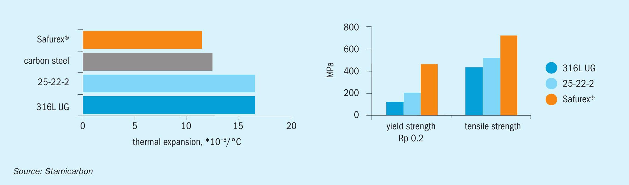
- superior properties in term of corrosion resistance and high mechanical strength in combination with low thermal expansion. The thermal expansion coefficient of Safurex® is almost identical to that of carbon steel as indicated in Fig. 5. Equipment in Safurex® therefore has a much lower risk on buckling or other types of deformation due to differences in thermal coefficients;
- it is not prone to strain induced inter-granular cracking. Thus, the heating rate of the reactor is less strict compared to the old reactor. The heating rate of the reactor increased from 50°C to 60°C in the new reactor;
- it is not prone to active corrosion. Block-in time consequently can be extended, as long as the reactor wall temperatures are above 125°C, before the necessity of having a complete drain or re-passivation. Of course the mechanical integrity and the applicability of the non-Safurex® piping attached to the reactor in the HP section should be checked for the long block-in time;
- high reliable construction material with a proven track record for more than 25 years used in more than 200 items of all kinds of high pressure equipment.
Conclusions
With this operational example, Stamicarbon could quantify the added value of installing the high-efficiency reactor trays in non-Stamicarbon plants. The benefits of installing these trays in this specific plant could be clearly observed due to changing from no trays to high-efficiency reactor trays.
The process benefits of installing the high-efficiency reactor trays in this project can be summarised in:
- higher urea conversion
- less carbamate recycle
- lower steam consumption
- higher plant output
The mechanical benefits of using Safurex® as a material of construction for the liner are:
- to increase the mechanical integrity of the equipment by selecting steel with high strength;
- to eliminate many of the corrosion behaviour/failure modes, such as stress corrosion cracking and stress induced intergranular cracks;
- to lower the O2 content in the plant;
- the ability to block-in the plant for longer periods as long as the temperature is above 125°C and the other interconnecting pipes allow, plus more flexibility in term of start-up and heating up the equipment.