Nitrogen+Syngas 370 Mar-Apr 2021
31 March 2021
Safe handling and start-up of ammonia synthesis catalyst
AMMONIA SYNTHESIS CATALYST
Safe handling and start-up of ammonia synthesis catalyst
Ammonia synthesis catalysts have long lives and catalyst replacement is an infrequent activity. Many people will go through their careers in the ammonia industry without ever having to replace a synthesis catalyst and the infrequent nature of catalyst replacement means that many plants may not have direct experience of this activity. Ammonia synthesis catalyst can present a range of hazards throughout the replacement process, from transport through loading, reduction, start-up, shutdown and discharge, but the good practice illustrated in this article, and collaboration between catalyst suppliers and end users can ensure safe and successful catalyst changeouts.
JOHNSON MATTHEY
Good handling practice for safe and successful catalyst changeouts
With the exception of a few plants which use a ruthenium based catalyst, all ammonia synthesis catalysts in commercial operation use promoted iron oxide, which is then reduced to promoted iron prior to use – broadly similar to that developed by Mittasch in the early part of the 20th Century. Whilst it may seem that there has been little subsequent development, this is deceptive in that there is now a much greater understanding about the role of the various promoters and how to optimise their incorporation during catalyst manufacture.
Promoters can be categorised as structural or electronic. Some are added deliberately during production whilst others are found in the iron ore used to produce the catalyst. Electronic promoters increase the activity of the catalyst by changing the electronic nature of the catalyst surface. K2 O is the most important electronic promoter. Structural promoters act to maintain the active structure of the catalyst, in particular its surface area, under normal operating conditions. Alumina and calcium oxide are the most important structural promoters.
There is considerable interaction between the various promoters, and this can have a dramatic effect on initial reducibility, initial activity, and long-term stability. A thorough understanding of these interactions is vital in order to optimise the performance of the catalyst and to understand the safe handling of the material.
KATALCO™ series catalysts
A major improvement to iron-based ammonia synthesis catalysis was the development of KATALCO™ 74-1 in 1984. Although over 35 years old, this catalyst remains the highest activity iron-based catalyst available in the market. It was initially developed for use at low pressure in ICI’s AMV and LCA plants. More recently its high activity has been integral to the success of the Uhde dual pressure process. The main difference between KATALCO 74-1 and standard iron-based catalyst is the incorporation of cobalt. A unique manufacturing process ensures optimum performance. In addition to high activity, ease of reduction is a significant benefit.
Although KATALCO 74-1 is supplied in oxide form, metallic iron is the active form for ammonia synthesis and the iron oxide needs to be reduced prior to use by reacting with hydrogen:
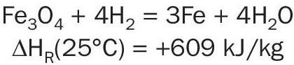
As the reaction is endothermic at low temperature, a source of heat is required to initiate the reduction.
A well-executed reduction takes place with a sharp and well-defined reaction front passing through the converter. Upstream of the reaction front the catalyst is reduced, and hence active. Downstream of the reaction front is unreduced catalyst with little ammonia synthesis activity. In most cases the source of the hydrogen is methanated synthesis gas. The presence of nitrogen in near stoichiometric quantities is beneficial because ammonia synthesis can occur over the active catalyst.
Water acts as an irreversible poison for ammonia synthesis catalyst during reduction and water that is generated must be kept to a low level. This is achieved by limiting the concentration of water to a level specified by the catalyst vendor (typically 1,000 to 3,000 ppm) and by performing the reduction at a low pressure to minimise the partial pressure of water.
Plant reduction can be a lengthy and costly process and in many cases it is the operational problems due to the plant (start-up heater / circulator / converter designs) rather than the catalyst that is the rate determining step.
If the catalyst is indeed the limiting step, an alternative is to use a catalyst with good reduction properties such as KATALCO 74-1.
Another good alternative is the use of KATALCO 35-8 or KATALCO 74-1R, which have been reduced and then passivated by carefully regulated exposure to oxygen to give a stable iron oxide skin around the active iron phase. Reduction of this skin is much easier (and faster) than reduction of bulk catalyst allowing a substantial decrease in the time required for activation.
The disadvantages with pre-reduced catalyst are a higher cost and the extra care that is required when handling the material. A common compromise is to use a mixture, with a small quantity of pre-reduced catalyst on top of a larger volume of standard catalyst.
Catalyst handling
Catalyst transport
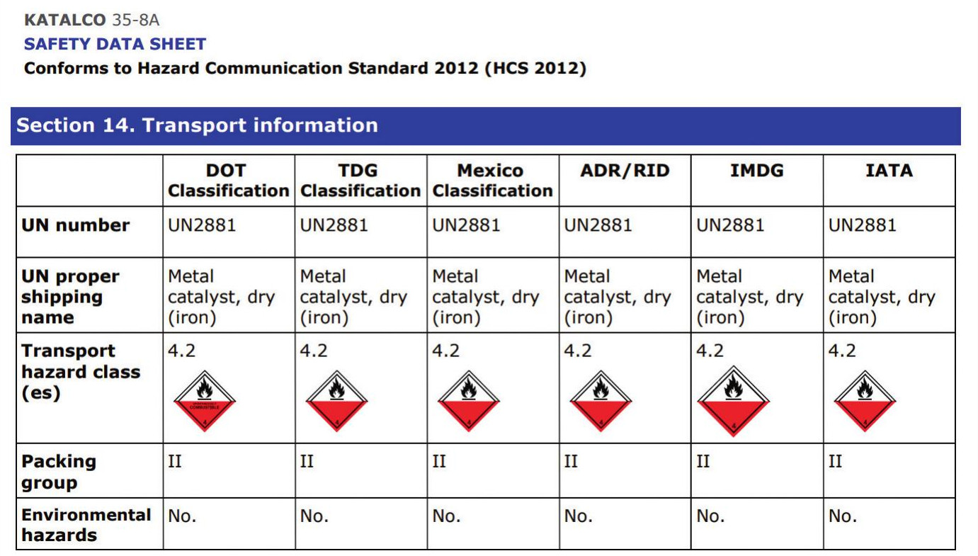
Catalysts are by design very active materials, for some products especially where they are pre-treated this brings to bear additional transport restrictions. Fig. 1 provides an example of the transport classification for pre-reduced KATALCO 35-8A ammonia synthesis catalyst on a safety data sheet.
Normally, for planned catalyst deliveries, sea freight is used. There are restrictions on what can be safely and legally transported using air freight, as a pre-reduced catalyst falls under Transport hazard class 4.2 “Spontaneously combustible substance”, since the catalyst can selfheat (without exposure to a heat source) when exposed to oxygen. Practically, this means it is not usually possible to ship pre-reduced ammonia synthesis catalyst by air.
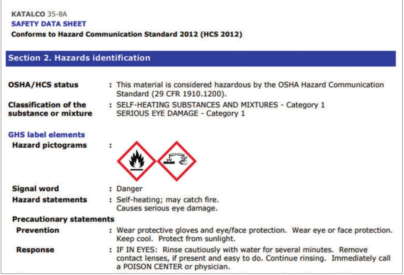
This relevant transportation information is provided on the MSDS/SDS, an extract from which can be seen in Fig. 2. Additionally, there is a requirement to label each package with a HAZ label.
Catalyst storage
KATALCO series ammonia synthesis catalyst is normally supplied in mild steel drums. These drums must not be stacked on their sides or stacked more than four drums high, even when held on pallets. Stacking of drums introduces both the risk of top drums falling from the stack, and the lower drums being crushed under the weight of the stack.
If the metal drums are to be stored outside, this should only be for a maximum of a few months, and they should be protected against rain and standing water. Longer term storage should be under cover and away from damp. To prevent contamination the lids should be left on the drums until just before charging.
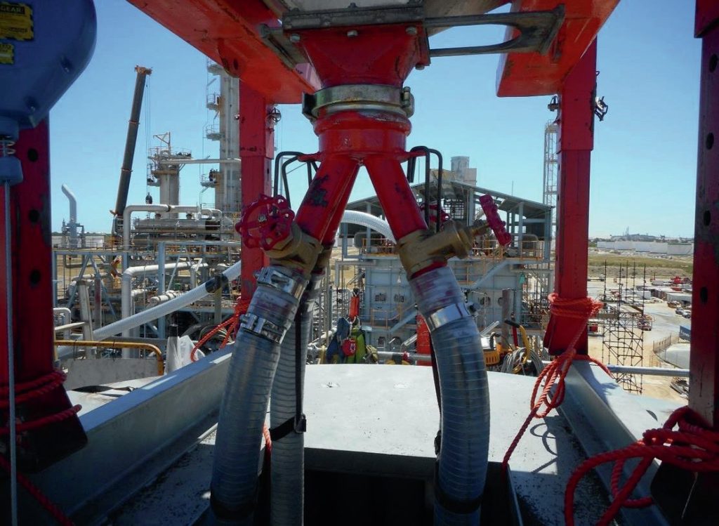
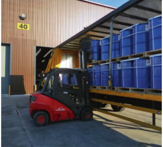
Catalyst drums must not be rolled. Careless handling of the drums risks damage to the catalyst. Catalyst drums are often supplied on pallets, which reduces the likelihood of damage in transit, but requires suitable fork-lift trucks (Fig. 3) and a paved area to handle the pallets. The fork-lift truck to be used for unloading the pallets should be fitted with rim or body clamps to avoid damage to the drums. It is important not to use standard forks to lift the drums under the rolling hoops, as damage to the drums and catalyst is almost inevitable.
Pre-overhaul checks
Since replacement of the ammonia synthesis catalyst is an expensive and time-consuming activity with long periods between scheduled replacements, and maintenance in and around the converter is difficult once the catalyst is in its reduced state, it is worth taking care to ensure that the ammonia converter is returned to service in good condition after a catalyst change. If the cartridge is not being replaced during an overhaul, it is worthwhile analysing the performance of the converter to diagnose any potential issues which can be addressed during the overhaul.
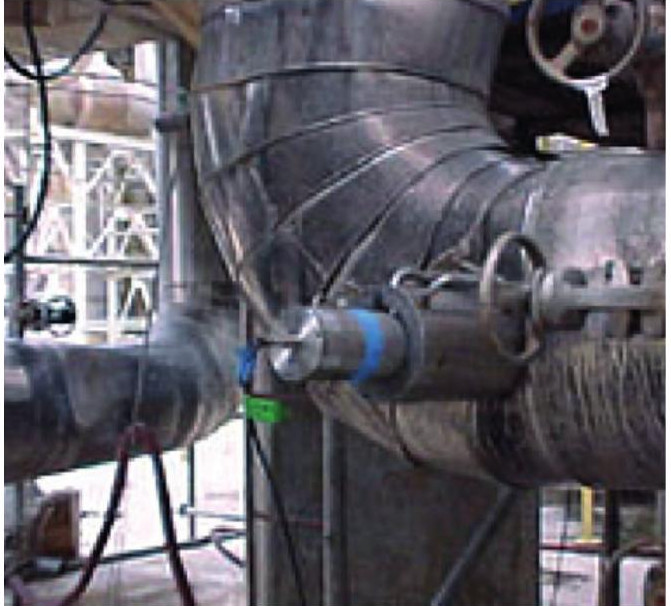
Johnson Matthey can assist in performing such an evaluation using KATALCO Performance software and CFD modelling capabilities. If this proves inconclusive a Tracerco™ diagnostic check could also be carried out. This might involve injecting a radioisotope to check whether there is internal leakage through an ammonia converter (Fig. 4). These activities should be carried out sufficiently in advance of the overhaul to implement contingency plans should any defects be highlighted.
Catalyst installation
Once in the overhaul, and in addition to recommended mechanical inspections, typical pre-charging checks include:
- catalyst support grid integrity;
- cleanliness of internal heat exchangers;
- checking internal heat exchangers for leakage and possible bypassing (Tracerco process diagnostic techniques can again assist with this);
- quench and bypass valve operation;
- thermocouple positioning and operation (warm each in turn, check corresponding indication in the control room);
-
ensure the vessel is dry before any catalyst is charged;
-
clean any residual dust and debris from the catalyst beds prior to charging;
-
ensure the catalyst is in good condition.
An even gas flow through the converter is key to ensuring optimum converter performance, therefore the catalyst loading method needs to ensure uniform bulk density and hence uniform pressure drop characteristics. This is especially important with radial flow beds to prevent voids in the catalyst bed and the resulting bypassing of gas. The density of ammonia synthesis catalyst is high and any equipment set up to handle the catalyst must be capable of withstanding its weight.
A rigorous and effective risk assessment should be carried out prior to catalyst charging. This should use advice from the catalyst supplier, the cartridge supplier and the plant designer. Protective clothing should be specified with due regard to the Material Safety Data Sheet (MSDS), local legislative requirements and operating company standards. As ever, special attention should be paid to the safety of confined space entries and to the asphyxiation hazards associated with nitrogen.
There is potential for the exposure to dust during catalyst loading. Catalysts should be handled in well ventilated areas and in manners that limit the formation of dust. Appropriate protective clothing, gloves and goggles should be worn, and respiratory protection should be used. All personnel involved in catalyst handling should wash afterwards, and clothing should be changed at the end of each shift as a minimum to prevent contamination.
Pre-reduced catalyst
Whilst there are many references of KATALCO 35-8 and KATALCO 74-1R being safely loaded into converters, there are a few features which should be considered when generating risk assessments and job methods. These are highlighted below.
If the oxide film around the reduced material is damaged, reduced catalyst is exposed to air. The reaction with air is highly exothermic and hence the catalyst particle heats up. As the temperature increases, the oxide film becomes a much easier barrier for oxygen to penetrate and hence a self-heating phenomenon occurs. Whilst a single particle has a large surface area and can transmit the heat of reaction away easily, in an ammonia converter, the heat of reaction is conducted to adjacent particles which then heat up, allowing oxygen to penetrate to the core of these particles and further increasing the temperature.
If there is no air flow through the packed bed, the concentration of oxygen falls as oxidation occurs and the reaction can no longer be self-sustaining and ceases. If oxygen is readily available, a temperature runaway is possible. As the density of the hot air in the bed decreases it will rise out of the bed, drawing in fresh air which allows the oxidation reaction to continue.
The protective oxide layer can be damaged by attrition and by moisture. The use of good quality catalyst, which does not require sieving, is recommended. Excessive vibration should also be discouraged. Excessive moisture can affect the protective layer and dehumidified air has also been used with success.
Additional precautions include keeping the catalyst cool (<50°C, 120°F) during handling. If exposed to hot tropical sun the catalyst can act as a black body and absorb the sun’s heat until it becomes self-heating. Under such conditions, catalyst charging should be carried out under shade.
During catalyst charging, the vessel thermocouples must be fitted and operational to allow monitoring the temperature of the catalyst. If caught in time, the effects of catalyst heating can be accommodated by applying a nitrogen blanket. It is therefore necessary to have a readily available source of nitrogen and to keep a careful watch on the temperatures. The temperature should be monitored throughout the charging process until the converter is boxed up and under nitrogen.
If the catalyst reacts with air it will consume oxygen, and there is potential to generate an oxygen-deficient atmosphere during catalyst charging. It is recommended that the vessel is charged from outside if possible. If it is necessary to enter the vessel, breathing apparatus (BA) is recommended. Personnel entering the vessel must be fully aware of the possible hazards and a rescue plan should be established to enable them to leave the converter quickly and safely should temperature rise occur. Once it is safe to do so, a nitrogen blanket can then be established.
Standby personnel should also be wearing BA. BA should be used even if no nitrogen purge is activated since the pre-reduced catalyst will slowly consume oxygen within the confined space and may evolve some residual ammonia. No ventilation should be provided to avoid excess oxygen ingress promoting the exothermic oxidation reaction.
Reduction
Whilst the reduction procedure is quite simple, the effect of the synthesis loop means that a simple change in conditions takes much longer to settle down than would be the case with a once-through process.
Water evolved during reduction should never pass over catalyst that has been reduced, and this is achieved by keeping the unreduced beds at a lower temperature. The water concentration leaving the reactor should be controlled in accordance with the recommendations of the catalyst supplier.
The water is removed via the loop catchpot. This may be difficult at low loop pressure and it can freeze in the chillers if the refrigeration system is running. As ammonia solution freezes at a much lower temperature than water, ammonia is sometimes added to the loop before reduction commences. This means that the refrigeration system can be brought online earlier thereby minimising the water concentration in the circulating gas.
Gradually, the reduced catalyst at the inlet of the reactor will start to make more ammonia. At this stage, catalyst temperatures need to be controlled carefully (often by increasing the circulation rate), otherwise the reduction will become too rapid and may result in the catalyst temperature falling. Rapid temperature changes are always bad for a catalyst bed but, due to differential expansion, the catalyst is particularly vulnerable if it is partially reduced during such a change.
As the reduced catalyst produces ammonia, the reduction water contains an increasing level of ammonia. The ammonia liquor condensed from the reduction loop requires safe handling, storage and disposal.
As more catalyst is reduced, the heat of the ammonia synthesis reaction gradually becomes the dominant heat input. This allows the circulation rate to be increased tremendously, and so each bed takes roughly the same length of time to reduce even though the downstream beds contain much more catalyst.
The circulation rate is normally increased by opening the converter inlet valve a little. This directs more cool gas to the first bed and will cool/hold the bed temperature. It can also affect the flow through shot/bypass valves and therefore the flow through the various beds and interchangers. Adjustments to the inlet valve should be very small until the “feel” of the converter has been established. If a plant trip occurs a forward flow through the converter must be maintained by purging downstream of the converter to prevent reduced catalyst standing in a stagnant atmosphere containing water as this will reduce the final activity of the catalyst. If it is necessary to de-pressure the loop the catalyst should be held under a dry nitrogen atmosphere.
Shutdown
When an ammonia converter is taken offline it is important to exclude air, water and other possible catalyst poisons. The simplest way of doing this is to leave the loop at pressure, the only complication being that liquid ammonia may condense in sections of the pipework which are normally above the condensation temperature. If the pressure is subsequently reduced and the ammonia boils it may produce pipework temperatures below their design limits. A blow through with warm nitrogen or synthesis gas can avoid this problem.
In the right circumstances it is possible to reach temperatures much lower than the boiling point of ammonia (-33°C, -27°F, at atmospheric pressure) and, in the limit, it is possible to reach the adiabatic saturation temperature (-72°C, -98°F).
If the pressure in the loop is to be reduced to atmospheric, a positive nitrogen purge must be kept through the catalyst. It is wise to minimise the flow of nitrogen, even if it contains only a few ppm of oxygen, to avoid re-oxidising the catalyst.
When the loop pressure is reduced there is a possibility that water or steam may enter the synthesis loop due to any leaking heat exchangers. Special care is required under such circumstances, and if there is any doubt the water side of these heat exchangers should be de-pressured.
Re-oxidation will lead to a temperature rise and it is good practice to check bed temperatures every hour or so. Bed temperatures should be checked more often when work which can lead to oxygen ingress is in progress.
Unloading
Ammonia synthesis catalyst must be handled with great care when in the reduced state. In extreme circumstances, oxidation of ammonia synthesis catalyst can generate an exotherm of up to 1,600°C. Air must not be allowed to flow through reduced catalyst (e.g. by transporting in open containers) as this can create a chimney effect and draw more air into the catalyst.
Stabilisation is best carried out by slow oxidation. This can be achieved by keeping the catalyst wet and exposing it to air (over several days) outside of the vessel. The catalyst should be kept in a thin layer between 150−300 mm (6−12 inches) deep to allow it to cool easily. Self-heating can occur if the catalyst is dumped in heaps. Hydrogen is evolved by the reaction with water and the area should be well ventilated. Sources of ignition in and around this area should be identified and eliminated to prevent the evolved hydrogen from igniting.
Simple vessels are usually discharged by sucking out the material under nitrogen to prevent excessive oxidation. Air can be drawn into the top of the vessel and through the top part of the catalyst, but with sufficient nitrogen flow upwards through the remaining catalyst the quantity of hot material can be minimised, and trouble is unlikely. Nevertheless, temperatures must be watched carefully and if they become too high, the sucking must be stopped and the nitrogen blanket re-established.
Ammonia synthesis catalyst can be stabilised before discharge by circulating nitrogen with a suitable compressor and carefully introducing air. Complete re-oxidation is not necessary, and it is best to keep the catalyst temperatures between about 70 and 100°C. Even when stabilisation has been carried out it is advisable to keep a nitrogen supply available and to monitor bed temperatures carefully, as there is a possibility that some pockets of the catalyst will not have been stabilised and if a hot spot develops it can spread quickly.
Another method of stabilisation is to fill the ammonia catalyst basket with demineralised water. Demineralised water is used because converter internals are usually made of stainless steel. Since hydrogen will be slowly evolved, care must be taken to avoid accumulation creating an explosion hazard. Not all ammonia synthesis cartridges are suitable for filling with water. They may not be strong enough or they may contain insulating material, which should not be wetted. This feature should be checked with the manufacturer before the procedure is agreed.
It is not recommended to use steam in place of water to stabilise the catalyst as the hydrogen production is more rapid and effective stabilisation is not achieved.
Another point to note is that any unreduced iron left within the converter can potentially react with air to produce an oxygen deficient atmosphere and this possibility should be addressed as part of the confined space entry procedures and precautions.
Case studies
Catalyst loading into a Casale revamped reactor
Two converters on a Kellogg ammonia plant, were revamped with Casale internals. KATALCO 74-1R pre-reduced ammonia synthesis catalyst was selected for use in all three of the beds in both converters.
JM not only supplied the catalyst and the technical support services during catalyst reduction, but also arranged for inspection of the baskets during their fabrication and acted as a validator for the project.
To unload the previously installed catalyst, the converter was filled from the bottom with water to oxidise the catalyst. After the catalyst had been flooded for 36 hours, the basket was removed, and the oxidation of the catalyst began. The catalyst remained stable, but after two hours it caught fire due to high wind. After containing the fire, the catalyst was emptied into bins where it again began to glow after coming into contact with air.
Although the previous charge of catalyst had been flooded and no longer appeared active, there was enough residual activity to present a fire risk on exposure to air.
In preparation for loading, initially job methods called for the charge to be sieved, but as no dust was collected, job methods were revised to those suggested by JM. KATALCO 74-1R is considered suitable for use direct from the drum normally with no need to screen sieve.
The loading was started under dehumidified air. Due to hot work on the baskets, and the flammable nature of the rope ladder used in the converter, there was a fire during the loading. The air flow was stopped and nitrogen flow was started from the bottom of the converter. Following this, the rope ladder was replaced with an aluminium ladder. Measurement of the catalyst temperature showed that the catalyst had reached 160°C, and therefore work was stopped and the catalyst cooled under a nitrogen purge.
Contributory factors to the incident:
- damage to the passivation layer of the pre-reduced catalyst can result in oxidation exotherms, the unnecessary sieving of KATALCO 74-1R;
- lack of isolation leading to a chimney effect in the converter;
- flammable materials should not be present inside the converter during loading.
Following the rapid reduction of the KATALCO 74-1R charge, the converter effluent was vented to ensure that there was no residual dust that might damage the compressor. No dust was observed in the venting gas.
The customer was extremely happy with Casale and Johnson Matthey for the workmanship, product quality and technical support services during the operation.
Remote support for catalyst loading and reduction into a Topsoe converter
A new S-50 ammonia converter was installed during a plant turnaround in July 2020. The catalyst for the new converter was KATALCO 35-4 supplied by Johnson Matthey.
Since it was not possible to travel to customer sites due to Covid-19 travel restrictions in July 2020, JM were able to provide remote support to the customer in the loading and delivery of catalyst.
The quantity of catalyst supplied by JM was calculated based on the information provided during the tender. However, since there was information lacking regarding the dimensions and the exact volume of the catalyst beds, the supplied volume was approximately 20 m3 less than the volume available to fill.
Since the new converter was a radial bed, JM emphasised the point that it is very important that the catalyst bed is completely filled up to the bed covers and that it must be filled in such a way that loaded catalyst density for the entire bed is consistent and meets the target density to avoid voids in the catalyst bed and insufficient contact time for the required ammonia make.
JM recommended that the catalyst bed must be fully loaded with catalyst up to the cover plates and to the target density. Since additional catalyst needed to be procured to fill the bed as soon as possible, JM was able to offer available UK stock of KATALCO 35-4A for either sea freight or airfreight for delivery.
As part of the remote support for the loading, JM provided a catalyst operating manual, loading manual and log-sheets to the customer and offered advice on loading methods and vibration methods to ensure the correct loaded density of the catalyst.
JM also provided remote support to the reduction of the KATALCO 35-4 catalyst. Guidelines for the reduction of the catalyst were provided and a dialogue maintained between JM and site personnel. JM offered recommendations on reduction temperatures and reviewed reduction log sheets to assess the progress of the reduction.
Following completion of the reduction, the S-50 converter containing KATALCO 35-4 has operated successfully.
Catalyst loading into a KBR horizontal converter
In this case, the loading of the ammonia synthesis converter was to be carried out by a EPC Engineering crew under the guidance of both EPC and KBR engineers. Johnson Matthey was requested to provide additional support and was present for catalyst loading activities and training to ensure JM’s loading standards were achieved. The loading was monitored by JM, KBR and EPC and inspections were carried out after each distinct layer was loaded.
Before the loading commenced, all preloading checks and requirements were completed. The vessels were inspected, the internal dimensions were checked against the mechanical drawings and the bed dimensions used for the loading calculations were confirmed to be accurate. The bed mechanical integrity was confirmed and the clearance to load was issued following the initial level markings.
The KATALCO series catalysts were inspected prior to loading and found to be in exceptional condition with no particles outside of the size range and very little dust. The drums were periodically inspected by JM and KBR to ensure the quality of the catalyst was maintained and all drums were found to be in very good condition.
The KATALCO 35-4 series catalyst was transported to site and kept in a designated shelter area close to the loading platform. From the shelter area the drums were lifted to the loading platform. All drums were always kept shaded in between layer loadings.
The KATALCO 35-8A and KATALCO 35-8C catalysts were supplied as pre-reduced and stabilised metallic iron. A meeting was held between JM, KBR, EPC and the site safety team regarding the loading of the pre-reduced catalyst KATALCO 35-8 in the ammonia synthesis converter. Although Johnson Matthey pre-reduced catalysts are specially designed to be stable when loaded in air, KBR specify in their loading documents that loading of pre-reduced catalyst must be done under nitrogen purge. JM supported KBR’s decision to load the catalyst under a nitrogen blanket.
With expertise in the loading of catalyst in a nitrogen or oxygen deficient atmosphere, JM provided training and advice and recommended the use of breathing apparatus (BA) to eliminate the risk of a compromised atmosphere in a confined space. Detailed loading procedures and safety recommendations were communicated clearly to all participants.
Prior to commencing the loading, the nitrogen source for maintaining the inert atmosphere was identified and checked to be secure and reliable. All other nitrogen consuming activities were considered to ensure that adequate supply to the vessel blanket could be maintained.
Access and egress routes from the converter were assessed and established and the area around the converter was designated an exclusion zone with hazard barricading and signage placed around one metre m from the top cover and the base of the scaffolding. Atmosphere checks were carried out on a routine basis and multiple bed temperature measurements were taken and constantly monitored.
This extra precaution allowed the Bed 1 catalyst to be loaded in less than 12 working hours, without any temperature build-up or safety issues.
The loaded bulk density of the catalyst was checked after the loading and vibration of each distinct layer by the JM/KBR/EPC supervisor in order to ensure that the required target density had been achieved. All beds successfully achieved the target densities to within 1% of the target and the loading was confirmed to be very successful.
A close working relationship between JM, KBR and EPC and the site management team ensured a well-managed, safe and successful loading of the new build plant.
Loading catalyst into tkIS uhde® ammonia converters
Traditional methods of loading ammonia synthesis converters often included a step in which vibration is carried out across the bed to increase the catalyst packing density loading. Typically, after a 30 cm layer of catalyst was loaded a template was used to guide a pneumatic vibration device in repeatedly settling the catalyst, it is a discontinuous process.
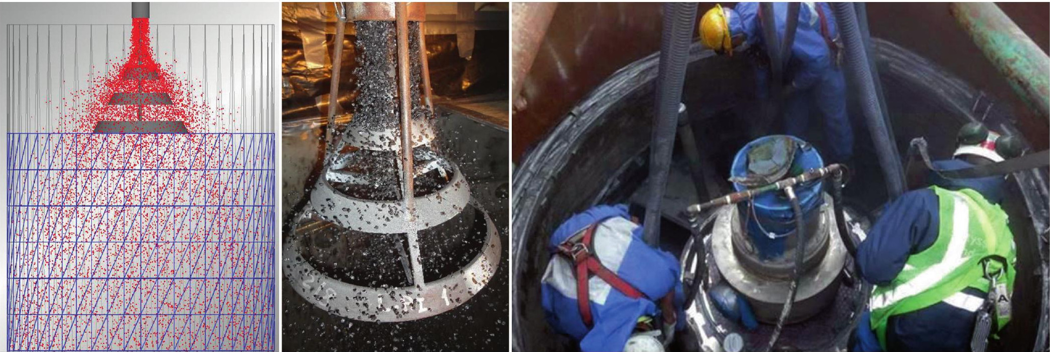
Working jointly with tkIS in seeking loading improvements for use in uhde ammonia converters, JM developed the concept of a special conical distribution head to ensure even ammonia synthesis catalyst loading (Fig. 5). The design was checked and improved using DEM (discrete element modelling) to optimise the precise shape of the device and ensure it worked at a loading rate as fast as possible.
The device was tested in a full-scale testing rig at JM laboratories in the UK and it was seen to achieve loading densities matching those of vibrated catalyst loading, with very uniform spreading being witnessed in which the momentum of the catalyst was used continuously to settle both KATALCO 35-8 and KATALCO 74-1R pre-reduced ammonia synthesis catalysts to the desired loading densities.
The testing also confirmed that multiple loading heads could be used to increase the converter loading rate, the resulting loading process takes only approximately a tenth of the time versus traditional methods. The continuous loading process also leads to safer jobsite activities with less direct personnel exposure to catalyst, as the loading can be managed externally from the top and reduces the need for personnel to enter the confined bed space in the converter basket as it is loaded.
The loading method has been successfully used in all of tkIS uhde® ammonia converter designs loading either KATALCO 35-8 or KATALCO 74-1R pre-reduced ammonia synthesis catalysts and includes the world’s largest plants operating reliably at 3,300 to 3,670 t/d.
CLARIANT
ActiSafE™ : The next level of safe ammonia synthesis catalyst reduction
Clariant has developed a safe, efficient, and accurate method for measuring both water vapour formation and ammonia concentration during ammonia synthesis catalyst activation. ActiSafE technology measures water vapour formation at the outlet of the converter during ammonia catalyst activation and provides several advantages such as continuous real-time measurements of the water vapour and ammonia concentration. The real-time data allows plant operators to respond quickly to changes in water vapour formation and to optimise the reduction procedure, saving time, avoiding catalyst poisoning, obtaining a longer catalyst lifetime, and higher ammonia production.
Ammonia synthesis catalyst is delivered as iron oxide and the activation of the catalyst consists of reduction of iron oxide to elemental iron, using hydrogen in the synthesis gas. During the reduction, oxygen adhering to the iron crystallites reacts with hydrogen and forms water vapour, which is separated by condensation in downstream processes.
The reduction does not produce nor consume heat in any noticeable amount. However, heat must be supplied to reach catalyst temperatures where the catalyst is reduced. It should be mentioned the faster the catalyst heating rate, the higher the formation of water vapour.
The water vapour formed is a poison for the synthesis catalyst and has a direct impact on the formation of active sites; therefore, the formation of water vapour must be limited to certain concentration levels during the reduction. The main control criteria for the reduction of ammonia synthesis catalyst is a steady gas flow with a steady heat input, giving a well-controlled, moderate temperature increase in the catalyst bed(s) to keep exit water vapour levels within the desired limit.
Controlling the water vapour produced via the catalyst heating rate is therefore extremely important during the reduction. High heating rates can lead to excessive water generation, resulting in low catalyst activity, while too low a heating rate might cause a delay in production and lost revenue. Therefore, an accurate and continuous measurement of water vapour formation during the catalyst activation is crucial.
By using ActiSafE, a non-dispersive infrared (NDIR) based technology, the formation of water vapour can be monitored continuously, so the speed of reduction can be controlled and optimised to obtain the highest catalyst activity, fastest activation time, shortest time to production, and thereby better profitability of the plant.
Impact of water vapour formation on catalyst activity
Proper activation of the ammonia synthesis catalyst is very important, mainly because the pore structure is developed during the reduction. The catalyst pore structure is a very important parameter for catalyst activity because it facilitates gas access to the active sites. A slow reduction provides a fine pore structure and a large surface area in addition to a maximum number of active sites, hence ensuring the highest possible catalyst activity.
The formation of water vapour as a product of reduction has a negative impact on the formation of the pore structure and will poison the catalyst active sites. Furthermore, too high a level of water vapour will inhibit the ammonia reaction, which is exothermic, and the heat of this reaction is needed to assist in faster heat-up of the downstream catalyst beds since total heat input is usually limited by the capacity of the start-up heater.
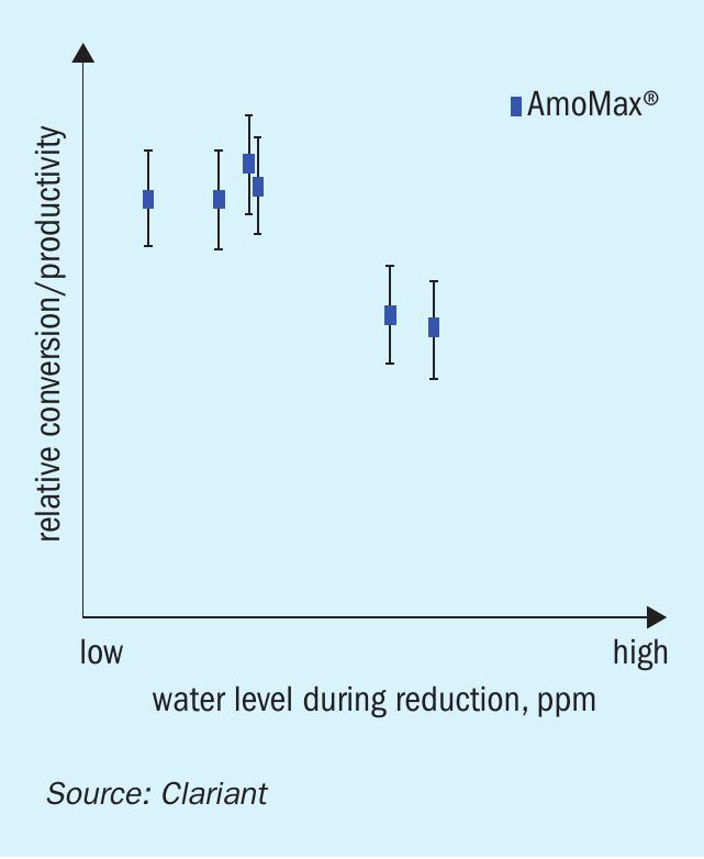
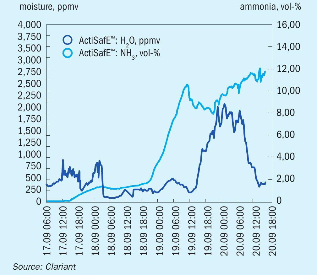
Clariant has carried out multiple investigations to assess the impact of water vapour formation on catalyst activity during the reduction. Fig. 1 illustrates that maximum catalyst activity (this is reflected by ammonia concentration at the outlet) is obtained at low water formation during the reduction. In this experiment, water formation was adjusted by varying the flow rates, while maintaining constant heat input and pressure. A low flow rate results in a high water concentration and vice versa.
Conventional method for measuring water vs ActiSafE
Due to the adverse effects of water, it is important to be able to determine the water content at the outlet of the converter correctly. Currently, three analytical methods are widely used to determine the water vapour formation at the outlet of the converter during the reduction. These commonly used methods are known as Ascarite, Carbide, and Karl Fischer titration method. All three methods have some operational challenges, such as:
- Human errors must be avoided – the accuracy of the method requires highly experienced laboratory technicians.
- The Ascarite and Karl Fischer titration methods are far too cumbersome to be used by ordinary laboratory technicians. These methods are very time consuming and there is a delay before information about the water content of the sample is provided (the result of each reading may take three to four hours).
- All of these methods require a lot of chemicals and a high number of technicians.
- Condensation in the sampling line may not be detected on time, giving an error reading.
- Due to the discontinuous nature of the measurements (time delay), the speed of catalyst activation is normally slow, which could cause a delay in production costing a lot of money. If the water formation exceeds the limit, the ammonia reaction can be inhibited and will prolong the activation. For example, oneday production loss can cost $700,000 for a 2,000 t/d ammonia plant (assuming an ammonia price of 350 $/t).
- The time delay of the measurements prevents plant operators from being able to counter any sudden increase in water concentration (e.g. by reducing the temperature) before permanent damage is caused to the catalyst.
In contrast, the ActiSafE method developed by Clariant provides several advantages, which include:
- continuous real-time measurements of the water concentration in a range of 100-6,000 ppm, while also measuring the ammonia concentration at the same time;
- DCS system connectivity;
- there is no manual operation requirement as the instrument has an analog output and can be connected to the DCS system of the plant for monitoring the real-time values in the control room;
- quick reaction time;
- real-time data allows plant operators to react quickly to changes in water content and optimise the reduction procedure, thus saving time and avoiding catalyst poisoning, resulting in a longer catalyst lifetime and higher ammonia production;
- faster and safer reduction;
- by using ActiSafE, the reduction itself can be sped up within a safe range to obtain the highest possible activity without any risk of production delay;
- high activity and optimised operation conditions;
- measuring ammonia concentration at the converter outlet enables catalyst performance to be optimised by adjusting the bed temperature, hence ActiSafE will ensure high catalyst activity and optimise catalyst operating conditions to maximise plant profitability.
ActiSafE demonstration
ActiSafE has delivered on its promises when it has been tested in the field. During the field tests, the accuracy, reliability, and practicality of ActiSafE have been evaluated.
ActiSafE equipment consists of a single benchtop device, providing easy installation and use. It only needs to be supplied with electricity and lined up to the sample line, where care should be taken to avoid condensation. For optimum utilisation, the device should be connected to the DCS via the analog interface, providing real-time data in the control room.
Real-time measurement of the water vapour formation at the outlet of the converter enables plant operators to increase the reduction speed close to the highest possible level and to react immediately if this is required. The reduction can be performed in a safe, fast and accurate way in all cases. Monitoring the ammonia content gives information about the catalytic performance of the already reduced bed and the generated heat, which is in most cases essential for heating the beds downstream.
Case studies
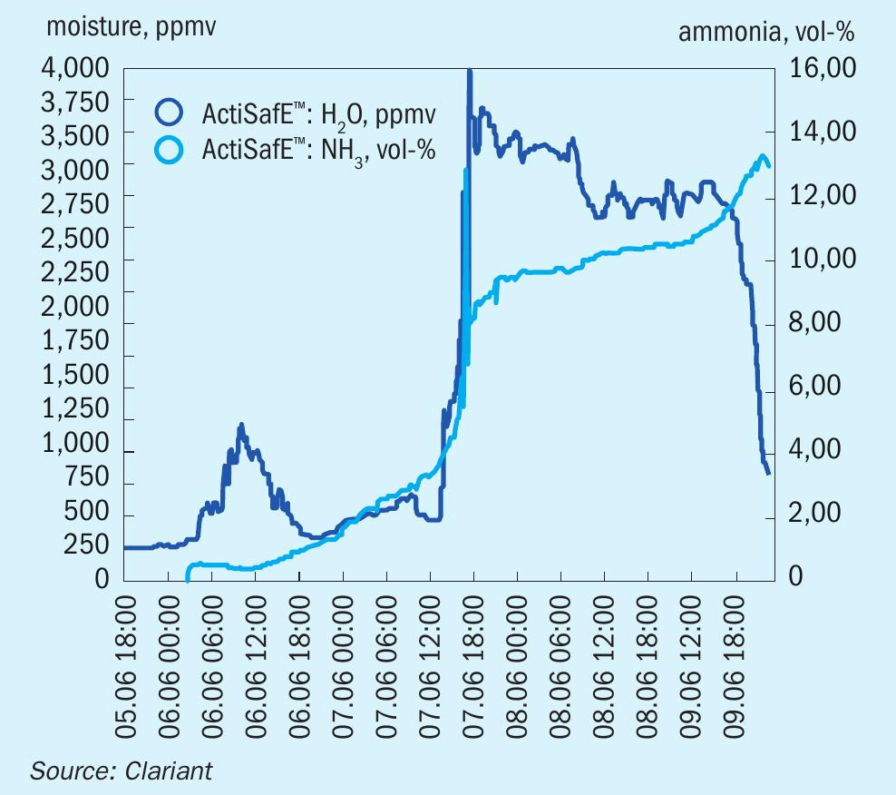
The success and convenience of ActiSafE has been demonstrated at several reductions at a client site. Fig. 2 illustrates the reduction of a 950 t/d plant in Europe in 2018, where the temporary failure of the start-up heater was a particular challenge. With the help of ActiSafE the reduction was finished within the timeframe. The plant production above design capacity demonstrates the high quality of Clariant’s AmoMax catalyst and the proper reduction.
ActiSafE showed reliable results during synthesis catalyst activation and was able to optimise and speed up the activation process without stressing the catalyst by forming too much water vapour. The information was also available during process disturbances, at any time of the day, without time delay and without the need for additional laboratory staff. In addtion, instantaneous concentrations rather than averaged values are measured giving a more realistic picture of the situation when compared with other techniques such as the Ascarite, Carbide or Karl Fischer titration methods. Having a more realistic picture increases the confidence of the operator who has full control over the reduction procedure. This is crucial as ammonia synthesis catalyst reductions are quite rare events for the production site.
Fig. 3 shows the reduction of two catalyst beds in a 850 t/d plant in Europe in 2019. It exemplifies how the reduction process can be accelerated with ActiSafE. For each bed the water vapour content was kept close to the upper limit which ensured a high reduction speed throughout the activation. During regular plant operation, the converter pressure could be decreased while keeping the production rate above design capacity.
CASALE
Catalyst dense loading using Casale tools

The necessity to maximise catalyst load quantities together with the requirement to achieve a uniform catalyst density across the catalytic bed led Casale to develop its own dense loading procedure based on the use of Casale loading tools.
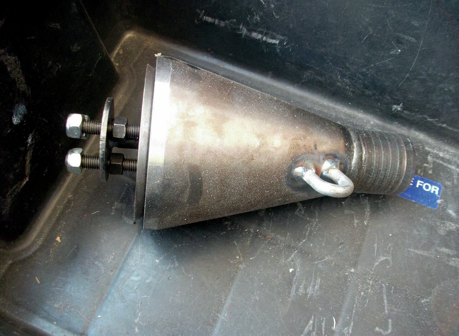
Casale loading tools have been widely used for catalyst loading in Casale ammonia converters since the 1990s. Compared to different commercial dense loading systems now in use with catalyst contractors, Casale loading tools (Fig. 1) are simple, have no moving parts, and can be fabricated easily by customers on site. Several tools sizes are available. Selection of the type and number of tools to be used is tailored by Casale for each project, based on experience, to get the best catalyst loading results. Casale typically specifies the type and number of tools required in order to provide a total loading speed of about 1 m3 /h.
The Casale dense loading system comprises a fixed hopper placed on the top of the converter, valves, plastic hoses, Casale loading tools and a frame to support the tools.
Loading speed is regulated using valves corresponding to the fixed hopper. The catalyst in the plastic pipes connecting the hopper and the loading tools is always free falling.
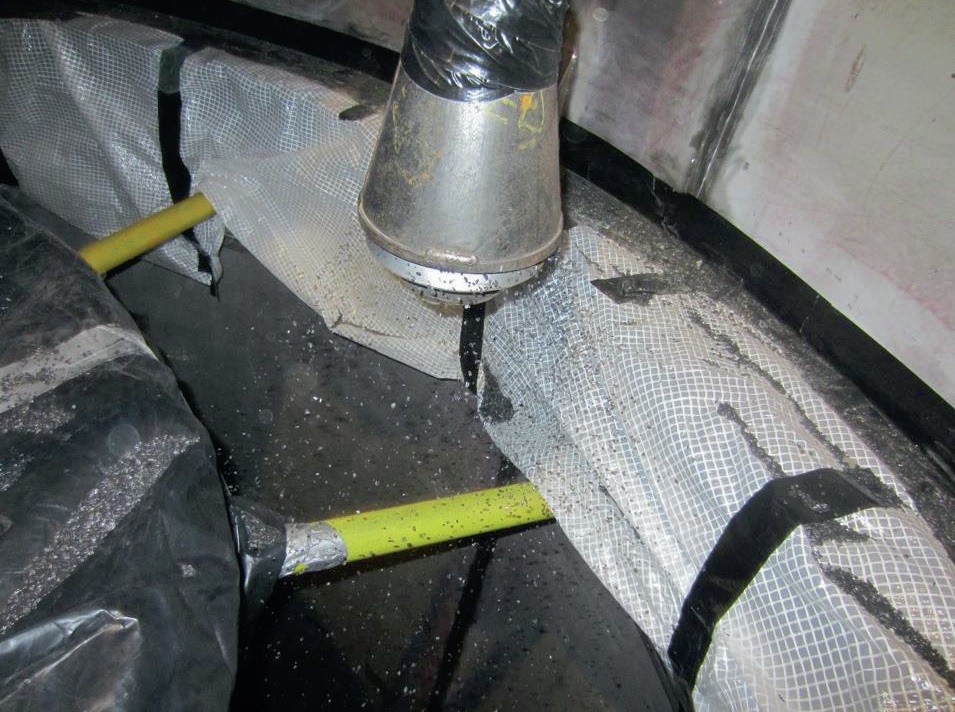
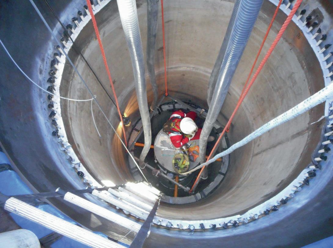
One operator is required to stay inside the converter in the upper part to operate the tools and to provide even distribution of the catalyst, while the catalytic bed is being loaded (Fig. 4).
Even though human presence is not required in other automated loading systems, Casale considers it an advantage to have an operator on site to control the loading process and avoid undesired situations that could occur when there is no physical monitoring of the job (maldistribution, sealing failures, catalyst presence in gas areas).
Pre-reduced catalyst is required to be loaded in cool and dry air, but with all the provisions to swap to a nitrogen atmosphere if a rise of catalyst temperature is detected.
Temporary thermocouples are used to monitor the temperature of the pre-reduced catalyst during loading.
The catalyst falls in plastic hoses to the tool, where it impacts a cone which acts like a sprinkler, evenly distributing the catalyst in all directions (Fig. 3). The catalyst falls from the top of the catalytic bed to the bottom. This system has been used with good results for a maximum free-falling height of about 12 m for oxidised catalyst and about 10 m for pre-reduced catalyst.
A loading operator is not required to access the catalytic bed, because no vibration or raking is required, making this loading system safe and suitable even for very slim catalytic beds, where human access is not possible.
The Casale dense loading system results in a very high and uniform catalyst density throughout the bed height, an important factor in obtaining the best performance from the converters.
Catalyst unloading
Casale has participated in the unloading of hundreds of catalyst charges from ammonia converters during its long history of supplying and revamping ammonia converters and has developed its own bed design to facilitate this operation that can sometimes be quite difficult and time consuming.
Ammonia synthesis catalyst is usually unloaded via vacuum in a nitrogen atmosphere. Nitrogen vacuumed with the catalyst is recycled and sent back to converter after cooling to reduce the nitrogen costs.
Catalyst passivation for further unloading in air is strongly discouraged, as steam flow control in the gas going through the catalyst is a difficult task. Major damage to the converter internals, and even melting of the steel components have been reported in the past.
To avoid catalyst vacuuming, the open-top ammonia converter designed by Casale can also be unloaded via a drop-out nozzle. This feature was introduced about 15 years ago, and was originally designed for slim converters where operator access for vacuum purposes was not possible and unloading by basket tilting was not a preferred option.
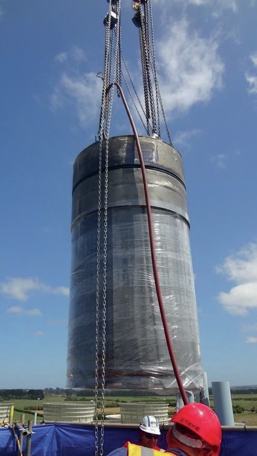
The catalytic bed full of catalyst is designed to be lifted out of the cartridge (Fig. 6) and is easily unloaded by opening the drop-out nozzles provided on the bottom of the catalytic bed.
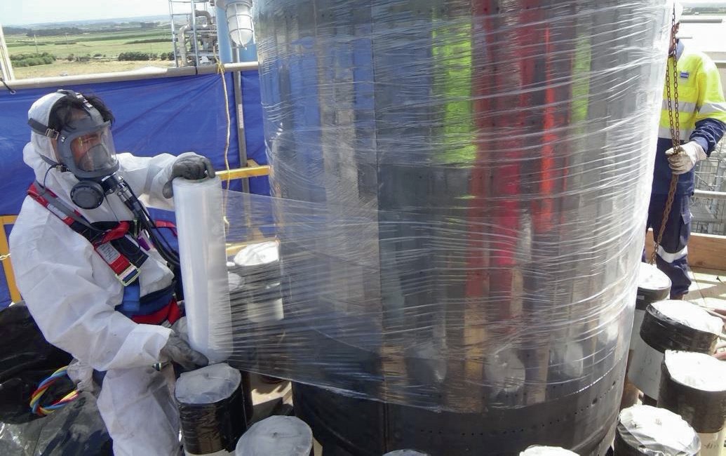
The catalytic bed, continuously purged by a nitrogen source feeding a sparger pipe, is wrapped in plastic during its removal from the cartridge to avoid oxygen coming into contact with the active catalyst and consequently raising its temperature.
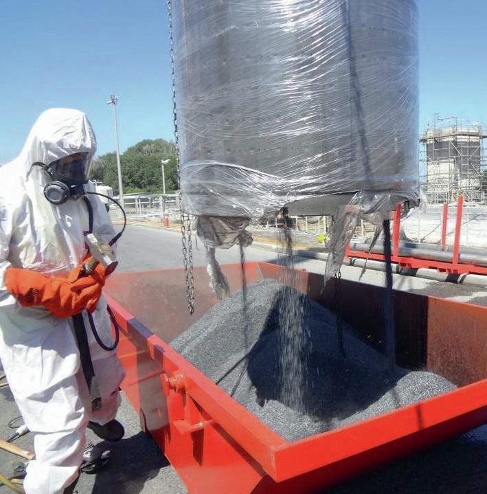
The basket is rested on a proper structure and the drop-out nozzles (two or three) are opened one by one, dumping the catalyst into dedicated skips (Fig. 7).
The use of drop-out nozzles requires heavier liftings to be executed for the removal of baskets full of catalyst, but greatly reduces the time required for catalyst unloading work, as well as reducing the time spent by personnel working in a confined space with a life support system.
The nitrogen quantities required during unloading are also significantly reduced when using the drop-out nozzles for unloading.
Casale designs baskets that can be lifted full of catalyst for small to medium catalyst volumes of up to about 15 m3 . For bigger volumes, a design using special lifting devices can be applied.
An additional advantage of baskets that can be lifted full of catalyst is that they can be pre-loaded outside of the converter, and in parallel, before their installation, reducing the time required for catalyst loading activities and improving the safety of this operation.
HALDOR TOPSOE A/S
A safe solution for pre-reduced ammonia synthesis catalyst replacement
Nowadays, a catalyst is state-of-theart when it not only delivers superior operational reliability but also logistics strength. These features are of particular importance as the catalyst could reach an operational lifetime as long as 30 years, making the installation and activation of the new charge (i.e. replacement) possibly a once-in-a-lifetime experience for most of the personnel in an ammonia plant.
The pre-reduced Topsoe ammonia synthesis catalysts KMR 111 and KM1R are manufactured to deliver high activity during normal operation as well as to minimise the risks associated with handling and loading, while also ensuring a shorter start-up period.
The unloading, installation/loading and activation/start-up need to be meticulously planned to avoid any incidents, which could result in serious personnel injuries and/or equipment damage, while minimising plant down-time.
In general, any catalyst installation is associated with many hazardous activities. Among this, the confined space entry in a long and narrow reactor with limited egress is one of the most challenging from a safety standpoint; especially when the catalyst to be loaded is in its pre-reduced state as it is liable to self-heat in contact with air and without an energy supply. Furthermore, when this type of catalyst is not passivated to withstand the weather and work conditions found in a typical loading, the installation normally takes place under an inert atmosphere.
Consequently, having a stable ammonia synthesis catalyst in its pre-reduced state that can be installed in a normal atmosphere is highly valuable for any ammonia plant owner from a safety and economic standpoint.
Although installing a pre-reduced catalyst has the drawbacks previously mentioned, they are significantly outweighed by the incentive of reducing by two to four days the time that the plant is operating in transient conditions, i.e. activation/startup of the ammonia synthesis catalyst.
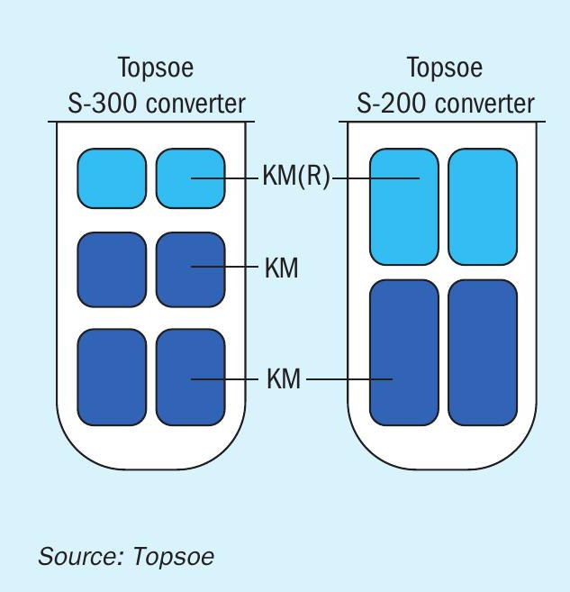
The benefits that the pre-reduced version of Topsoe KM catalysts have brought to the ammonia industry are tangible. In more than 1,200 charges of ammonia synthesis catalyst that have been successfully manufactured, installed, and activated, the vast majority have been loaded with Topsoe’s recommended combination of pre-reduced and unreduced catalysts (Fig. 1).
The path to highly stable pre-reduced ammonia synthesis catalysts
Clearly, the quality of the raw materials, the optimal amount of the promoters and the manufacturing procedure, are all key factors that determine the final quality of an ammonia synthesis catalyst. However, to produce a catalyst that offers both operational reliability and logistics strength, the path from production to normal operation must be carefully planned.
The steps that allow the production of a highly active pre-reduced KM catalyst that is safe to handle, transport, install and activate are discussed below.
Reduction
The two main factors that influence the intrinsic catalyst activity are the reduction procedure, specifically how the procedure is designed to limit the effect of water, and the particle size in which the catalyst is reduced from iron oxide to elemental iron.
The effect of water
Water and high temperatures are promoters of hydrothermal sintering. This phenomenon is characterised by the growth of iron crystallites, which has a negative impact on the catalyst activity as it decreases the available surface area and could also block or collapse pores, making the crystallites inaccessible to the reactants.
Additionally, water inhibits the ammonia synthesis reaction; which means that higher temperatures are required for reaction to take place.
Particle size
The larger the particle size, the longer it takes to complete reduction of a given particle and the more damage is therefore inflicted to the following catalyst layer due to water released in the reduction of this particle.
Reduction procedure
The reduction method influences the properties of ammonia synthesis catalysts.
The reduction procedure should ensure that the pore system, formed by the renewal of oxygen ions, increases the specific surface area of the catalyst as close as possible to the theoretical maximum. The characteristics of the pore structure that develop during the reduction also depend strongly on the heating rate and the gas composition (mainly H 2 O) to which the catalyst is exposed.
A controlled heating rate is important for the activity of the catalyst. It prevents rapid reduction, which leads to high water vapour concentrations in the gas that accelerates changes to the crystalline structure of the already reduced catalyst.
It is therefore of utmost importance to limit the amount of water vapour in contact with the catalyst and this can be achieved with a high space velocity. Although, an initial space velocity of 3,000-5,000 V/V/H is difficult to achieve in an industrial installation, it can be done in the manufacturing facilities of the KM catalysts.
A pre-reduced catalyst charge will then not only ensure a higher activity of the catalyst but also that the heat generated by the ammonia synthesis reaction will allow the plant to increase the space velocity and to keep it as high as possible throughout the activation of the charge. This will lead to a more controlled heating rate and a lower water vapour concentration in the exposed catalyst.
Passivation
A reduced ammonia catalyst is strongly self-heating when in contact with air even at ambient temperature. Consequently, the pre-reduced catalysts used in the industry have been given a passivation treatment upon reduction so that they can be transported and installed.
The passivation treatment is carefully conducted considering that:
- Skin oxidation has an influence on the pore structure and the surface area, since voids may be closed off and the mouth of the pores shrunk reduced.
- It is mandatory that KM-catalysts comply with the international transport regulations UN 2881 Metal Catalyst, Dry (Iron), Class 4.2, Packing Group II; which are part of the document “Recommendations on the Transportation of Dangerous Goods, Model Regulations”.
Additionally, the state-of-the-art passivation treatment given at manufacturing facilities provides Topsoe’s ammonia synthesis catalysts, KMR 111 and the industry-leading KM1R catalyst, with sufficient stability so that they can be loaded in atmospheric air.
Installation/loading
The loading of the catalyst is usually overlapped with the mechanical installation of the beds, inter-bed heat exchangers, among others, and it is associated with many high-risk activities such as: handling and exposure to hazardous substances, working at heights, and the most critical one, confined space entry in a long and narrow reactor with limited egress.
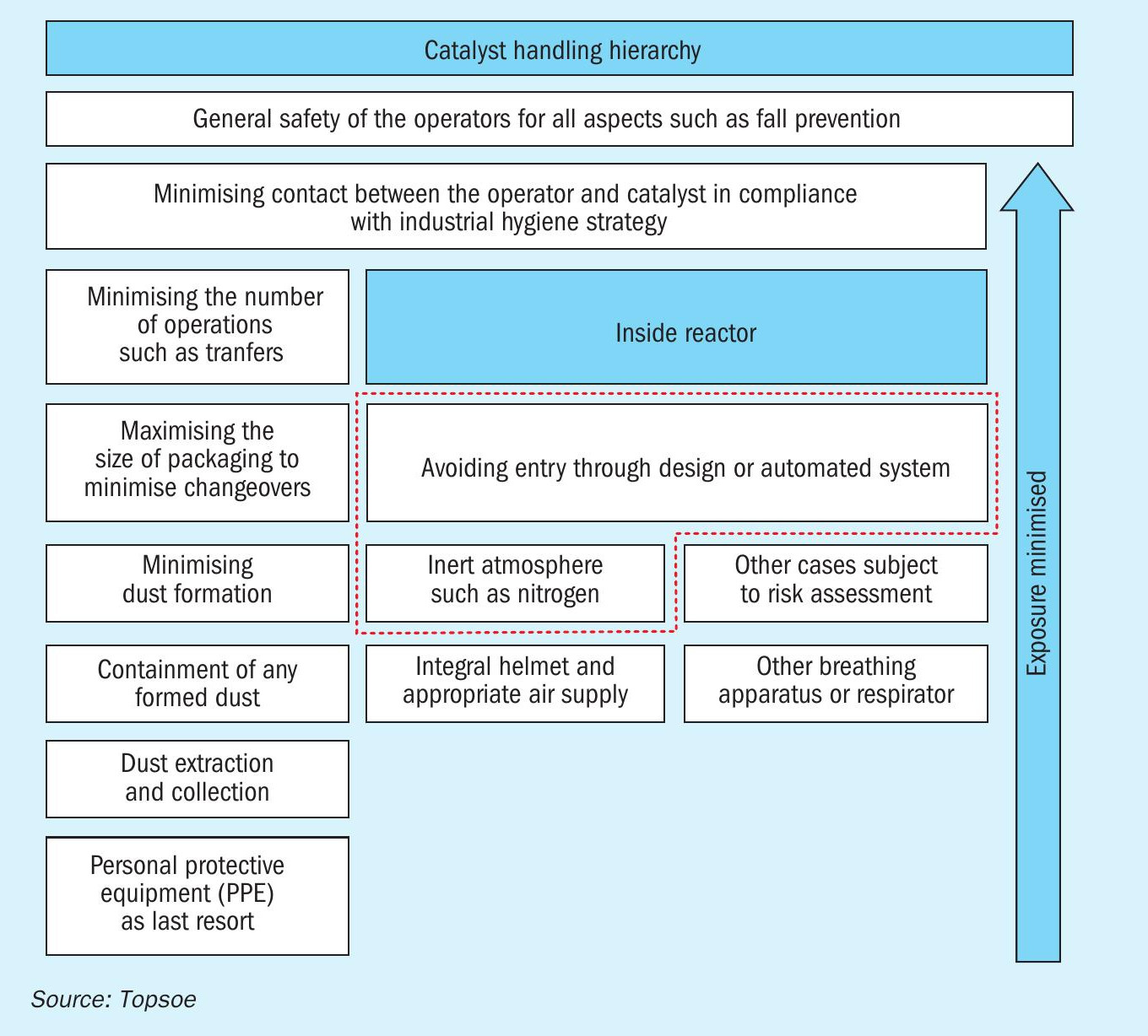
According to the catalyst handling hierarchy (see Fig. 2) issued by the European Catalyst Manufacturers Association, avoidance of reactor entry is the preferred option. However, if reactor entry is required, particularly in the case of inert/nitrogen atmosphere (or other potentially hazardous residual or incidental substances), an appropriate breathing apparatus such as an integral helmet and appropriate air supply is normally required.
Reactor inert entry is a high-risk operation and strict procedures are required including, in the case of European countries, Europe Conformity (CE) approved specialised equipment, supervision and training.
Over the past decade, at least two full charges of pre-reduced catalyst and over ten of the prereduced/unreduced combination have been installed in atmospheric air every year worldwide without any incidents, demonstrating that Topsoe pre-reduced KM catalysts possess a unique feature that allows customers to not only reduce the loading time, but also to avoid the additional safety risks and hazards associated with inert entry.
In addition, from an economic perspective the cost of loading a pre-reduced catalyst in an inert atmosphere can be at least 25% higher than loadings done in atmospheric air. These expenses are not insignificant when one takes into consideration that the cost of loading a standard size 80-m3 ammonia synthesis converter in a nitrogen atmosphere is approximately $200,000 (additional cost of one bed in a split charge is approximately $50,000).
Activation and start-up
The protective layer added during the passivation treatment must be removed again before the catalyst regains its activity for ammonia synthesis.
The amount of water formed during the re-reduction of the catalyst is much lower than the one formed during the reduction of the oxidised catalyst. While it is expected that the charge with only pre-reduced catalyst stops forming water as early as 36 hours after the activation has started, the full charge of unreduced catalyst will continue forming water during the first eight to ten days after the activation commenced.
However beneficial a much lower amount of water produced during the activation of the catalyst charge is, the biggest benefit of using pre-reduced catalyst is the possibility to reach design capacity within a few days.
In tests, the estimated production of ammonia during the activation of three 90 m3 catalyst charges with different content of pre-reduced catalyst (0, 30 and 100%) showed a significant increase in the production rate (twofold) when moving from a full unreduced charge to a split charge of pre-reduced (first bed) and unreduced (lower beds) catalysts.
However, this same step-up increase is not seen when moving from that same split charge to a full charge of pre-reduced catalyst. Due to this, the majority of the ammonia synthesis charges installed in the world are split loadings, but local circumstances, such as limitations on the disposal of water containing low concentrations of ammonia, can make a full pre-reduced loading optimal.
Topsoe is always ready to assist with finding the right loading scheme depending on requirements.