Sulphur 394 May-Jun 2021
31 May 2021
A safer and efficient way to cool strong sulphuric acid
STRONG ACID COOLING
A safer and efficient way to cool strong sulphuric acid
N. Clark, B. Avancini and V. Sturm of Clark Solutions discuss a novel technology, SAFEHX® , providing a new approach to the cooling of strong sulphuric acid. Prototype results are shown and indicate a safe and stable cost-effective technology. SAFEHX® can be extended to every heat exchanger system where corrosion, mixture risks, fouling, process liquid loss (or contamination) and temperature control are key concerns.
Strong acid cooling and energy recovery is fundamental for sulphuric acid plants. Although strong acid cooling coupled with energy recovery is still not a widespread practice, since the 1980s interest in it has been growing. Some proven technologies have been employed, but associated added risks limited the acceptance and proliferation of these technologies. Recently, Clark Solutions developed a new technology to remove these added risks and a 150 t/d acid plant already operates with a SAFEHR® heat recovery system – a patented inert trim cooler technology that can substitute conventional heat exchangers systems, reducing corrosion and hydrogen incident risks with the benefit of energy recovery. Another SAFEHR® system was supplied to a 3,200 t/d plant under construction.
With focus on innovation, Clark Solutions’ interest in enhancing process capacity and efficiency using cost-effective approaches motivated a further development, SAFEHX® . This novel technology is discussed in this article and uses the SAFEHR® trim cooler approach while shifting from sensible to latent heat and merging both heat exchangers into a single device. Along its development, SAFEHX® showed a set of advantages besides the intended increase in cost-effectiveness. An innate temperature control and extreme fouling resistance are characteristics that also enable the use of this technology in other industries besides sulphuric acid. This temperature control is the consequence of a pressure dominant system, since shell buffer fluid operates in a boiling-condensing regime, hence cold fluid will never heat above a set buffer temperature.
While SAFEHR® shows versatility in safe use ramifications (BFW heating, steam production, service water heating, conventional cooling, among others), SAFEHX® shows a compact and precise approach for safe heat transfer systems.
The SAFEHX® approach
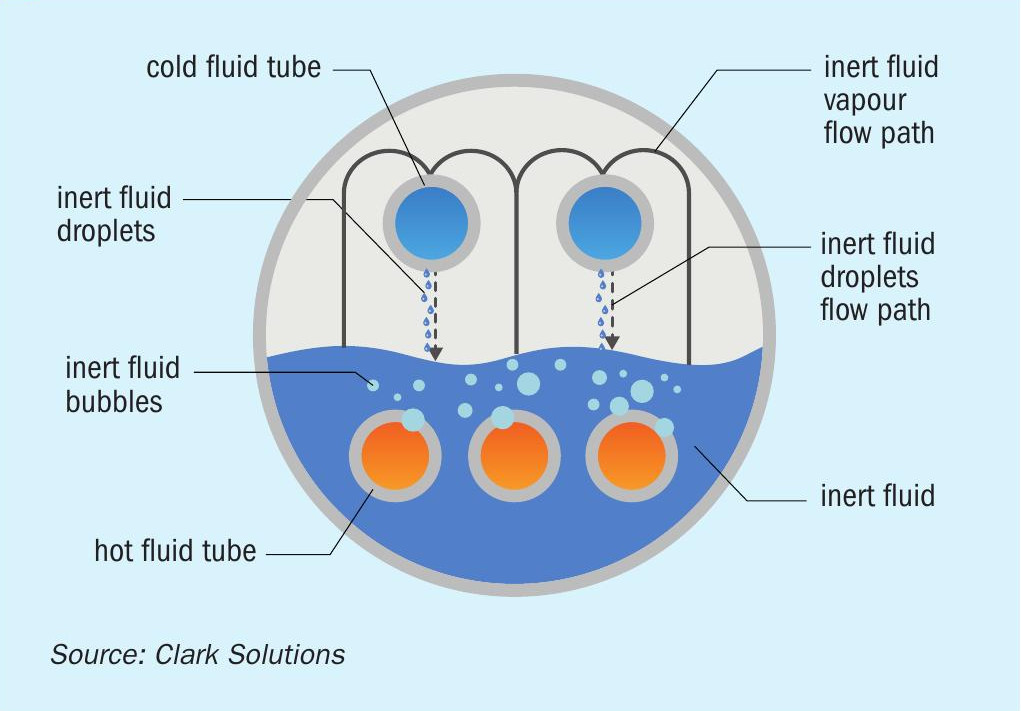
SAFEHX® is the concept of cooling hot acid, or other fluids, in a single three-fluid heat exchanger with a mutually inert fluid acting as a buffer fluid inside the shell. This design has a shell, and two or more sets of tube bundles. Bottom, submerged tubes provide heat to boil the buffer fluid, in opposition to the upper, emerged tubes, that retrieve heat and condense back this buffer fluid.
Buffer fluid flow inside the shell is generated by this boiling-condensing regime. Its fundamental purpose is to increase safety and reliability in heat transfer using a compact device enabled by latent heat, minimising damage due to mixing cold and hot fluid, and eliminating hydrogen generation and accumulation in the event of leak-associated corrosion.
Additional benefits were also identified and will be discussed later in this article. Fig. 1 shows a basic SAFEHX® scheme.
The SAFEHX® system comprises a single heat exchanger using a properly selected inert fluid as a buffer. In sulphuric acid plant applications, hot acid is cooled in the bottom tubes by boiling the inert fluid, the vapours flow upwards and are condensed by heating boiler feed water (BFW) and/or another fluid.
Flow direction is not a concern for either set of tube bundles, reducing connection and piping interferences. The equipment does not require shell baffles, facilitating manufacturing and maintenance and reducing costs.
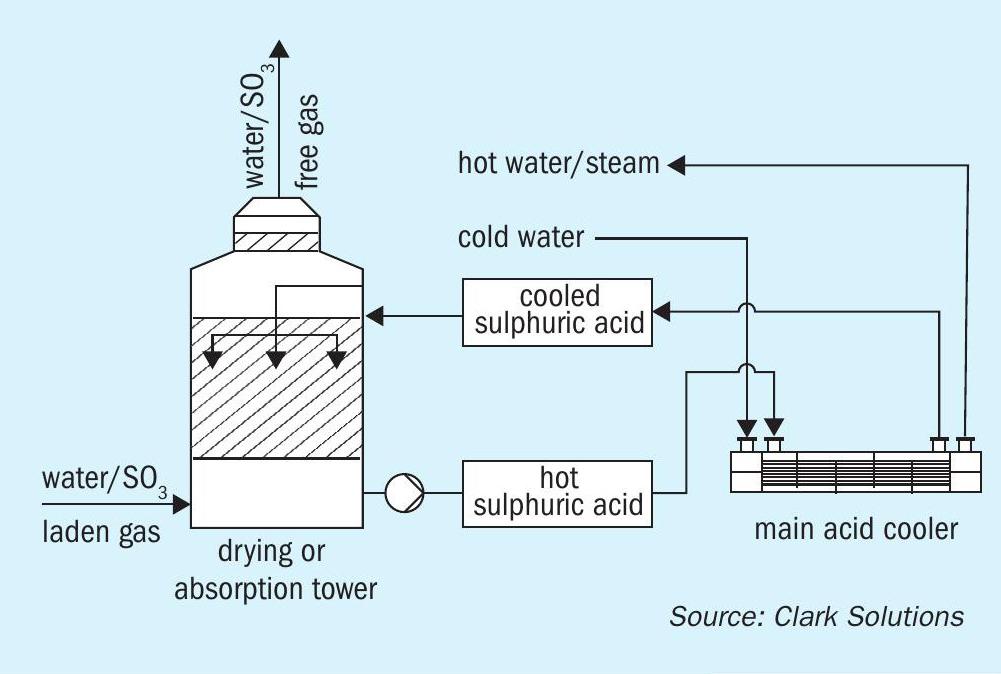
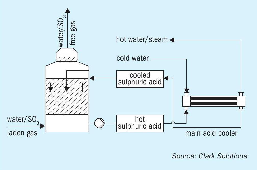
SAFEHX® can be used on a conventional acid cooling system or attached to a heat recovery tower as a safety and reliability improvement.
Fig. 3 shows how SAFEHX® would be integrated with the absorption tower and a prompt conclusion is that almost no change is required to install the equipment.
Inert fluid
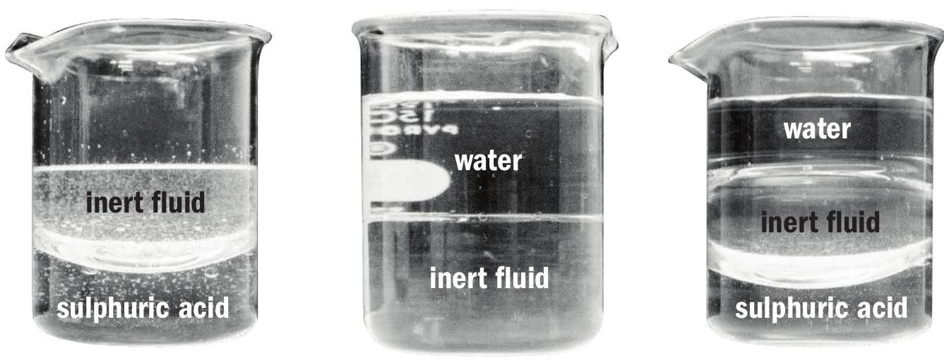
In the early 2000s Clark Solutions carried out development, extensive testing and evaluation of direct cooling of sulphuric acid by mixing with inert fluids. During this research a few families of fluids were found to have adequate properties:
- Stability: fluid can withstand processing temperature and pressures.
- Inertness: fluid must be inert to both hot and cold fluids, in this case, acid and water.
- Flammability: fluid had to be non-flammable.
- Toxicity: totally non-toxic.
- Corrosivity: fluid cannot be corrosive to steel and other alloys.
- Safe to handle: minimal or no handling or storage special requirements.
- Density: fluid density better to be inbetween water and acid densities.
- Heat transfer: good heat transfer properties.
The direct contact approach failed; the amount of fluid required was substantially high, fluid final temperature would be much lower than the acid temperatures, impeding any heat recovery, and the potential loss of fluid due to acid carryover on the acid stream could be costly.
While direct cooling did not prove to be commercially attractive, using the inert fluid provided an excellent approach for a trim cooling system and hence enabled SAFEHR® development.
For SAFEHX® , a similar set of characteristics was important, but different vapour pressures would be required to use the latent heat approach. But for different vapour pressures, the system would only require operating with different controlled pressures. This highlighted the potential benefit of high temperature control.
Different processes may use different buffer fluids which better interact with process-specific hot and cold fluids.
Safety and hydrogen incidents
On a conventional acid cooling system in a plant that does not recover energy, the flow through the acid coolers is undertaken in a condition that acid pressure is always higher than the cooling water pressure. Typically, in the event of a failure, acid will leak into the water side allowing identification by measuring water pH downstream of the coolers and avoiding dilute acid formation inside plant equipment. But leaks will heavily damage heat transfer equipment, contaminate water cooling system, and require a plant shutdown that may last from days to weeks, depending on the leak extent and response time.
On a heat recovery system, acid is always at a lower pressure than boiling water, which is pressurised up to 10 bar, depending on steam quality requirements. The large pressure difference between acid and water is a stronger driving force than the pressure difference in a conventional system. Therefore, a leak either initiated by corrosion, bad material and workmanship quality or even a stress issue will occur at substantially higher flow rates than that in a conventional system. Consequently, acid dilution and heat release rates will become higher, ultimately leading to critical failures.
Additionally, this leak region receives hot acid at 180+°C mixed with hot water to produce a dilute acid at even higher temperatures. Local conditions are tremendously aggressive.
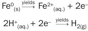
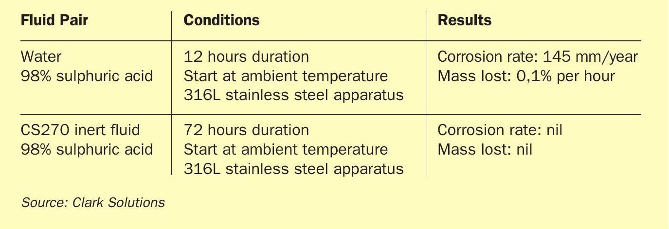
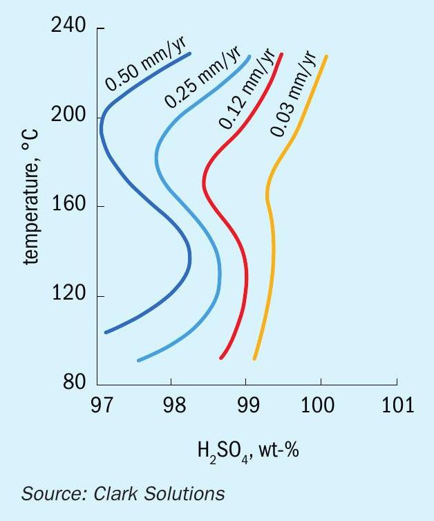
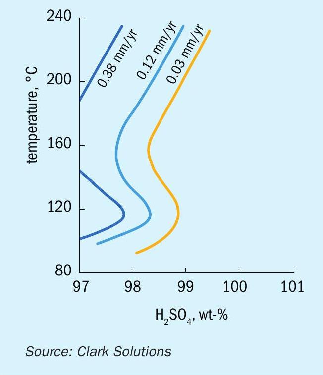
Studies of dilution induced corrosion progression developed by Clark Solutions show that corrosion rates of a 1 mm hole in an acid-water system at ambient temperature and pressure can be as high as 150 mm per year, with the hole diameter growing as much as 0.1% per hour in these mild conditions.
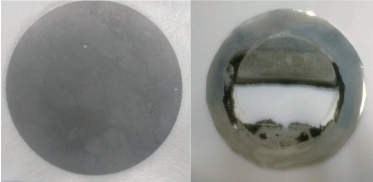
Using an inert fluid greatly reduces corrosion rates, even if a leak occurs. Table 1 shows results measured from these corrosion tests.
When in a heat recovery system, a water leak into the acid will dilute the strong acid in the system. The corrosion effects will occur inside acid plant equipment and hydrogen will accumulate in high spots. Several hydrogen explosions have been reported by the industry in the recent past.
Several actions and measures have been taken to minimise the risk of a disastrous failure in a heat recovery system due to leaks of hot, high-pressure water into acid.
From modern, sophisticated, and redundant concentration, corrosion and temperature digital monitoring and control to segregated heat recovery towers have been employed to reduce emergency shutdown probability. Advances in instrumentation have also substantially reduced risks with monitoring and safety measures. However, none of these safety schemes eliminate the root cause of the failure: acid-water contact. SAFEHR® , and now SAFEHX® , will never allow acid and water to mix.
Prototype
To ensure that Clark Solutions’ products are always functional and can be used on an industrial scale, a clear and direct methodology is followed. For this new product, a rigorous numerical study was carried out to size the prototype, using heat and mass transfer models.
Using the obtained results from this numerical study, Clark Solutions’ engineering team carried out a mechanical project, an experimental bench setup and an automation system aiming for a validation through quantitative results.
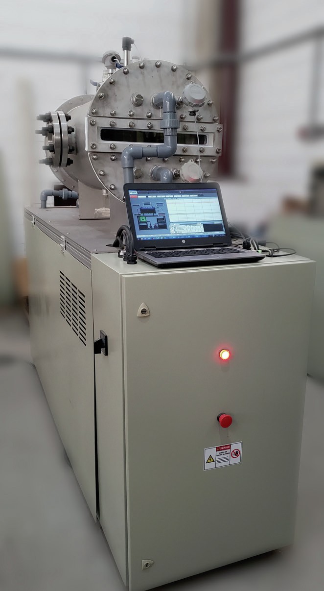
The experiment bench is presented in the Fig. 6. In its concept there were: two pumps, two volumetric flow meters, five thermistors and three pressure transmitters. All the bench control and data acquisition were held by the PLC and a supervisor system. The supervisor system was operated through a computer in which bench control was undertaken.
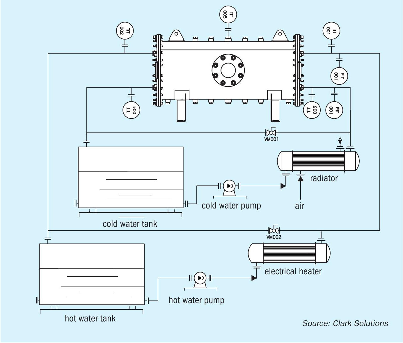
With the basic flow diagram of the bench in Fig. 7, we see that it has two closed-loop water cycles. One is called the cold-water loop. This loop has a tank, a pump, a flow control valve, one pressure transducer, two temperature transducers and one air radiator, to decrease water temperature. The other is the hot-water loop. This loop also has a tank, a pump, a flow control valve, one pressure transducer, two temperature transducers, but it has a heat resistance instead of the air radiator, to increase water temperature.
Experimental results
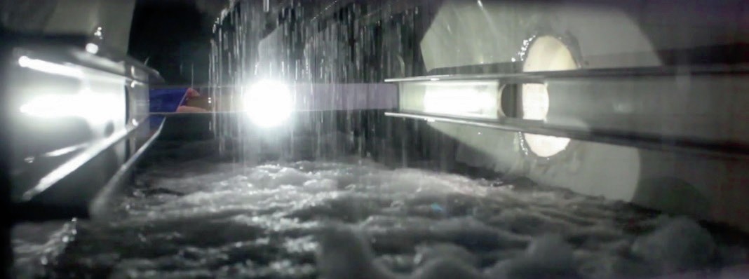
After several experimental bench tests to ensure that the instrumentation and system were working as expected it was possible to execute some prototype runs to verify the heat transfer capacity. As first evidence of the heat transfer phenomena, there is the visual of both boiling and condensation processes inside the heat exchanger shell. The boiling is verified by the froth which hides the submerged tubes, and the condensation is verified by the uniform dripping from the emerged tubes. Fig. 8 shows a very disturbed liquid surface caused by vapour bubbles and an intense flow of droplets dripping from the emerged tubes.
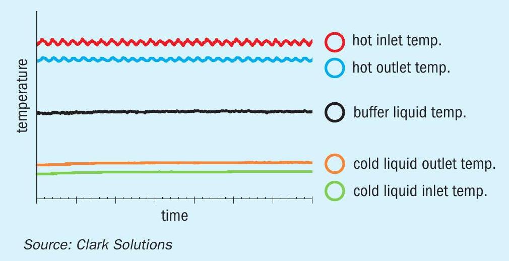
It is also worth mentioning the inert fluid buffer effect. As the temperature control system of the hot loop generates oscillations in the hot fluid temperature, it is possible to verify in Fig. 9 that no oscillatory behaviour is presented in the cold loop temperatures. This shows the high capacity of damping eventual temperature changes of a hot loop circuit and maintaining the heat transfer stable for the cold loop circuit. This is an important feature for processes that need to maintain heat exchanger performance with the safety of not crossing a minimum or maximum temperature.
As can be seen in Fig. 9, the buffer liquid maintains a constant temperature controlled by the SAFEHX® shell pressure setting point, which dominates the buffer liquid temperature. Even with oscillations on the hot fluid inlet, the cold fluid temperatures are stable. The system proved to be not only a safe means for heat transfer, but also an excellent system to control temperature.
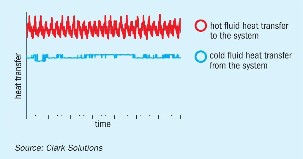
An overview of the heat transfer can be seen in Fig. 10, which further illustrates the dampening effect caused by the buffer fluid-controlled temperature.
The system was tested with varying heater output to change the hot fluid inlet temperature over time. The excess heat was subsequently transferred to the buffer fluid with some heat lost to the surroundings (not a perfectly adiabatic shell as observed from the gap between lines). This transferred heat from the hot liquid to the SAFEHX® system can be seen in the red lines of Fig. 10. But the erratic buffer liquid energy intake from the hot loop did not necessarily cause cold fluid to behave as erratically, this may seem contradictory at first, but this occurs due to internal energy variations of the buffer liquid which dampen system temperature variations. Blue lines have plateaus which are caused by changes in cold liquid flowrate and not differences in cold fluid temperatures.
Fouling resistance
Shell interiors and tube fins are typically difficult to maintain and clean, a problem that would never occur for the SAFEHX® heat exchanger.
Several heat transfer applications have fouling as a major concern for design and operation, as a consequence of either temperature-induced precipitation or feed particle content. As the buffer liquid does not have fouling characteristics and the shell is a closed-circuit, no material may precipitate or enter to cause fouling in the shell side.
SAFEHX® can also make use of finned tubes, giving a significant increase in area in a place where no fouling can occur, the shell side. Fouling can only occur inside pipes, and cleaning inside pipes is an easy and fast solution for the SAFEHX® even for high fouling systems.
Notwithstanding, this fouling inside pipes is also mitigated for operations where denaturation and precipitation concerns for the cold fluid are present, since the system shows an innate high precision temperature control for both buffer and cold fluid as shown above, reducing precipitation due to process oscillations.
Product loss and contamination
With a closed buffer fluid on shell side, any leaks of process fluid will not be carried away. In conventional heat exchanger systems, a leak will cause the fluid with more pressure to leak into the current with lower pressure. Within wide systems, retrieving specialty fluids may not be possible.
SAFEHX® can detect variations on the shell side to inform if any leak occurs, as unlikely as leaks may be considering inert fluid properties. In these events, the closed buffer circuit can then be carefully drained to retrieve any process fluids introduced inside the shell.
Risks of contamination are even lower, as this would require that a leak occur in both submerged and emerged tubes and would also require an existing pressure gradient from one to the other tube. Contaminating cold fluid with hot fluid, and vice-versa, is nearly impossible.
Materials of construction
Materials of construction for SAFEHX® pipes depends on the hot and cold fluids within the tubes, but a carbon steel shell can always be employed as the buffer fluid is inert. The SAFEHX® approach, due to its operational conditions, enables the shell to be constructed of common carbon steel alloys as the shell is only in contact with the inert fluid.
Despite using a carbon steel shell, the piping must be compatible with the process fluids. To be able to supply this technology for a wide variety of process, Clark Solutions can manufacture the SAFEHX® piping with almost any material.
Strong acid at normal absorption temperatures can be handled with a myriad of materials that proved efficient for such conditions. High silicon austenitic stainless steels like CSX™ and similar (CSX™ is the trademark for Clark Solutions high silicon stainless steel), 310 Stainless Steel, Alloy 20, and others have all proven resistant to different ranges of acid conditions.
Water tubes can be carbon steel or, where needed, stainless steel.
While proper material selection is very important to minimise failure risks, corrosion is a matter of time and operational control, and leaks eventually happen. In the case of a leakage event, sensors can identify any liquid entering the shell side to properly drain in a timely manner, if necessary. Even when corrosive liquids enter the shell side, the absence of oxygen inside will hinder oxidation and corrosion. It is possible to perceive that safety was a major issue when developing SAFEHX® .
SAFEHX® systems can be constructed in the materials suitable to any operating conditions.
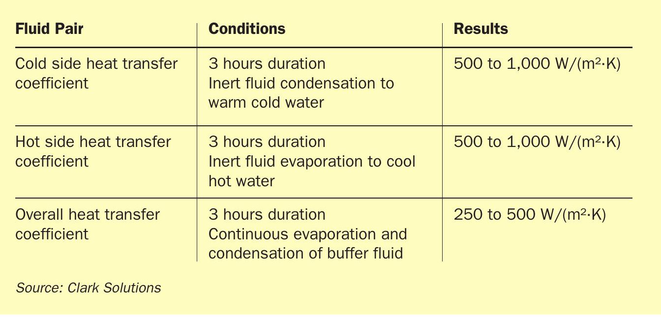
SAFEHX® performance
After processing sensors measurements, it was possible to verify that the heat exchanger, operating with a 1,000-1,200 litres/hour volumetric flowrate in the hot-water loop, was capable of transferring about 4 kW. The temperature and heat transfer results are shown in Figs 9 and 10. The cold-water loop flowrate of 1,0001,200 litres/hour retrieved roughly 3 kW of heat from the exchanger. The difference between those two heat rates came from the shell convection heat loss, due to the absence of insulation. The visible oscillations for the hot loop were caused by the on-off control of the hot water loop temperature. The overall heat transfer coefficients estimated from the prototype measured parameters were close to the numerical models and are shown in Table 2. Further prototype improvements and different sets of operation conditions were already issued and, just by installing shell insulation, an increase of at least 15% is expected on the overall heat transfer coefficient. As a starting point of the technology, there is already a prototype with heat transfer performance for liquids compatible with commercial products and with all the safety and process control improvements already mentioned.
Conclusion
SAFEHX® is a new, breakthrough approach, that adds a substantial safety feature to existing or new sulphuric acid plants. The prototype achieved its original objective of safe heat transfer in a compact device as originally intended. But it also benefits heat transfer operations with high fouling rates, operations where cold liquid temperature control is important, and cases where process liquid loss is costly. All of this can be achieved with cost-effective equipment. The prototype is in an advanced stage and a commercial version of the product should be available in 2021.