Nitrogen+Syngas 371 May-Jun 2021
31 May 2021
Blue technologies in the transition to lower carbon footprint
BLUE AMMONIA AND HYDROGEN
Blue technologies in the transition to lower carbon footprint
Reducing the carbon footprint in the synthesis of chemicals is a new global challenge as the world works towards providing sustainable products designed to minimise their environmental impacts throughout their whole lifecycle. This article looks at the role of blue technologies as part of a roadmap towards the decarbonisation of fuels and chemicals.
The declared commitment of governments, companies and other institutions to climate neutral production of goods and carbon-free transportation makes it necessary to have an energy carrier that does not contain carbon and offers a competitive energy density compared to today’s solutions.
In the transition towards completely decarbonised fuels, blue hydrogen and blue ammonia – whose production involves carbon capture and sequestration (CCS) or carbon capture and utilisation (CCU) – represent an attractive prospect.
The primary “blue” feedstocks, natural gas and coal, currently set the low cost benchmarks for storable energy commodities. With the addition of CCS, they are expected to set the low cost benchmarks for low carbon storable energy commodities.
Definitions have not been standardised yet. Some important aspects such as how much CO2 sequestration is needed to call a product “blue” and the boundaries of the carbon emission analysis still need to be defined in international standards.
Ammonia is the second most widely produced commodity chemical globally, with a production volume of over 180 million tonnes in 2019, and with approximately 20 million tonnes per year traded as merchant ammonia (mostly in the form of seaborne trade), mostly utilised in agriculture as a fertilizer, a sector that is under increasing scrutiny due to its environmental impact. Ammonia is one of the most energy intensive chemical products, responsible for the emission of large quantities of CO2 .
Ammonia can be synthesised from nitrogen and hydrogen via various methods, with the Haber-Bosch process currently the only method used on a commercial scale. The resulting ammonia can be easily transported, stored and the hydrogen can be extracted again at the destination via a thermal decomposition and separation process.
There are basically two routes to reduce carbon dioxide emissions: the first is to capture and sequestrate generated CO2 , resulting in so-called “blue” products; the second is to totally avoid CO2 generation by the use of renewable energy and feedstocks, resulting in so-called “green” products.
This article will focus on blue technologies. Green technologies will be featured in the November-December issue of Nitrogen+Syngas.
Ammonia as a marine fuel
When it comes to alternatives in the field of marine fuels (with IMO’s target of a 50% reduction in annual GHG emissions from international shipping by 20501 ) the use of ammonia as a substitute to heavy fuel oil gains importance, with the first ammonia fuelled ship already under construction. The growth of this supplementary market for ammonia is expected to become substantial: starting with 10 Mt/year in 2025 the use of ammonia as fuel will increase to 150 Mt/year in 20502 . It is obvious, that such an increase in ammonia production – in addition to the high and stable demand in the fertiliser industry – cannot be realised solely by future green ammonia plants. The gap has to be closed, at least in the beginning, by blue ammonia production, which is still based on the use of carbon containing natural gas.
Hydrogen as an energy carrier
Hydrogen and its use as an energy carrier is a hot topic and many economies are starting to transform their energy basis from carbon based feedstocks to hydrogen and are planning to build a hydrogen economy. Hydrogen can be produced from hydrocarbons through steam methane reforming (SMR), autothermal reforming (ATR), partial oxidation (POx), methane pyrolysis or by water electrolysis.
Presently, most hydrogen is produced industrially from the steam reforming (>95%) of natural gas and emits CO2 . Reducing direct emissions of CO2 and methane will determine whether the industry retains the right to operate in the future. Low-carbon technology and processes required to achieve near net-zero emissions exist and are well proven. To be a near zero carbon emission technology, the captured CO2 needs to be permanently stored. The economics and sustainability of CO2 storage remains uncertain in many cases and may not be available locally.
Historically, the standard process steps for hydrogen generation consisted of a steam reformer, high temperature and low temperature shift conversion, CO2 removal via absorption and methanation for final purification. After the introduction of PSA technology in the mid 1960s and rapid adoption of the technology since the early 1970s, the standard process changed to PSA technology rather than CO2 removal. However, the concept of applying CO2 removal units in hydrogen plants is a well-proven and mature concept which has been applied for decades. The concept of CO2 removal from process gas is applied in the front-end of ammonia plants which is very similar to the design of a SMR based hydrogen plant.
Blue hydrogen is often discussed for providing substantial amounts of hydrogen of more than several hundred thousand normal cubic metres per hour. This is particularly interesting for large scale consumers, such as steel production plants and large chemical production sites, which have a significant demand for hydrogen and require a continuous, uninterrupted supply. For example, the thyssenkrupp steel mill in Duisburg, Germany will use hydrogen in blast furnaces and in direct reduced iron plants for replacing coke in its steel production process. Blue hydrogen production closes the gap between the current carbon based economy and an economy entirely relying on green hydrogen as a long term solution.
Current ammonia technology
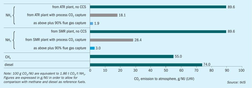
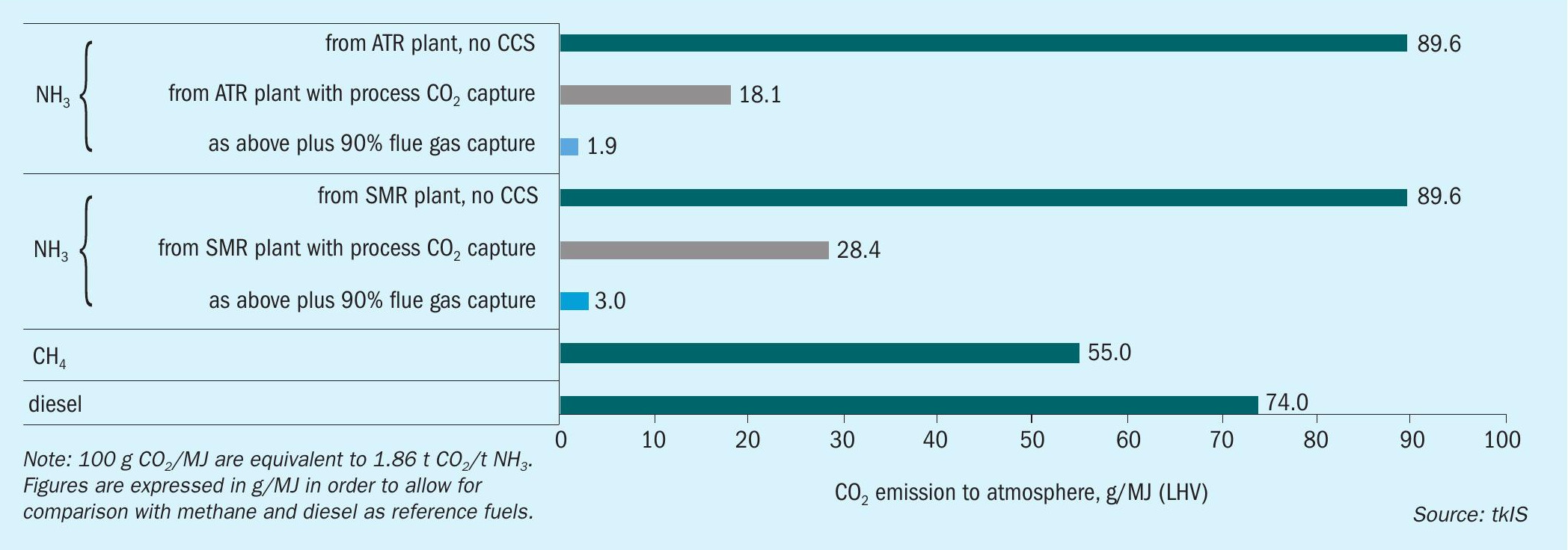
Reforming based ammonia production has two places where carbon from the natural gas is converted to carbon dioxide: On the process side, it is derived from the reforming and water gas shift reactions. In a conventional plant, it accounts for about 1.2 t CO2 /t ammonia. On the flue gas side, it is a result of natural gas combustion for heat release and for a steam methane reformer (SMR) based plant amounts to about 0.5 t CO2 /t ammonia for the primary reformer.
For a plant with an autothermal reformer (ATR), the total CO2 production is about the same, but with a different split between the two emission sources. Since heating for the reforming reaction in the ATR is provided by internal combustion of a part of the feed gas, the process gas contains and releases more CO2 and the required fired heater emits less than the steam methane reformer (see Fig. 1).
Blue ammonia
The major part of the CO2 in an SMR or ATR plant comes sequestration-ready as the CO2 has to be removed from the process gas anyway. Various technologies from different licensors are available. The CO2 removal unit in an ammonia plant usually produces a CO2 stream of >99% purity. Instead of venting it to the atmosphere, it is compressed to the required pressure level of the receiving system (approx. 130 to 160 bar), possibly dried and sequestered underground for final disposal.
The required installations for this can be added to any existing ammonia plant and can address about two thirds of the CO2 reduction potential as can be seen from the numbers above and from Fig. 1. If ammonia is intended to be used as a marine fuel, the CO2 emissions from it are thus already significantly below those of methane or diesel.
However, further reduction is possible by also treating the flue gas from the primary reformer or the fired heater. Several technologies exist, but as it is not a mandatory step in ammonia production, only a few reference installations exist today. For details refer to the following section on CO2 removal from flue gas. Fig. 1 shows the further reduction in CO2 emission if the flue gas is also treated to remove 90% if the CO2 contained in it. The figures for the process variants with CO2 capture include the additional energy for flue gas scrubbing and CO2 compression. It can be covered fully or to a large extent from the excess steam production from waste heat of the ammonia plant.
The flue gas CO2 removal unit can be installed in a new plant or as a revamp, and the recovered CO2 can be mixed with the separated CO2 from the process gas for compression and sequestration.
Of course, large-scale urea production which consumes CO2 as a mandatory feed stock cannot be combined with blue ammonia. However, the blue ammonia process (by revamp or by new design) does not have any impact on other downstream processes like nitric acid or ammonium nitrate production. These products inherit the low CO2 emission status from the ammonia they are made of.
CO2 removal technologies
Although the separation of CO2 from the pressurised synthesis gas by a scrubbing system is a very mature technology there are ways to improve the recovery rate and to lower the specific energy consumption, in order to lower overall carbon emissions. Improvements include an innovative process layout with additional vessels for enhanced recovery, flash gas recycle, new solvent formulations and high-performance column internals for improved mass transfer and lower pressure drop.
Compared to the CO2 removal unit in the process, the challenges of removing CO2 from flue gas are due to the fact that flue gas contains many substances such as NOx, SO2 , and O2 , which are detrimental to the solvents usually used for the process gas treatment, like amine solutions. Further, due to the lower partial pressure of the flue gas (close to ambient pressure) the driving force for the absorption is less, Therefore, for flue gas only a lower degree of CO2 separation can be achieved economically.
Typically, in such a unit the flue gas is pre-treated first in a scrubbing column. By intensive contact with circulating water, the flue gas is cooled and sulphuric gas components are removed from the gas. Subsequently the CO2 absorber column facilitates the separation of CO2 from the flue gas. The carbon dioxide is separated by means of an aqueous amine solution, which in turn is regenerated in a stripper column. In this column, the CO2 is released, cooled and routed to downstream compression.
For CO2 capture an amine blend is used containing a small amount of an activator component. The unit is designed for a CO2 capture rate of about 90%. Low pressure steam is used for the solvent regeneration. Backwashing sections in the top of the absorber and of the stripper column assure a high degree of solvent recovery and minimise solvent losses.
Ammonia licensor thyssenkrupp provides a proprietary process for CO2 capture from flue gas for revamps and for new built ammonia plants. The technology has been intensively investigated at pilot plant scale with steel mill gases and flue gas at thyssenkrupp’s multi-purpose testing facility. The Carbon2Chem® project and the sophisticated test centre is aimed at the chemical use of syngas and CO2 derived from steel mill gases for the production of ammonia/urea, methanol and other valuable chemical products3, 4 .
Current hydrogen technology
Hydrogen can be produced from a variety of hydrocarbon feedstock including natural gas, LPG, naphtha and hydrocarbon-rich off-gases (obtained as purge or waste streams in refineries). The main process steps consist of:
- feed preparation to adjust the feed pressure and to remove catalyst poisons such as sulphur;
- preheating of feedstock and mixing with steam;
- conversion of hydrocarbon feedstock and steam to hydrogen and carbon monoxide;
- conversion of carbon monoxide and water to hydrogen and carbon dioxide;
- purification of hydrogen to typically more than 99.9 vol-%.
Steam methane reforming
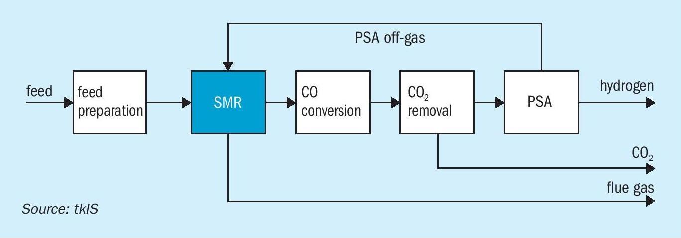
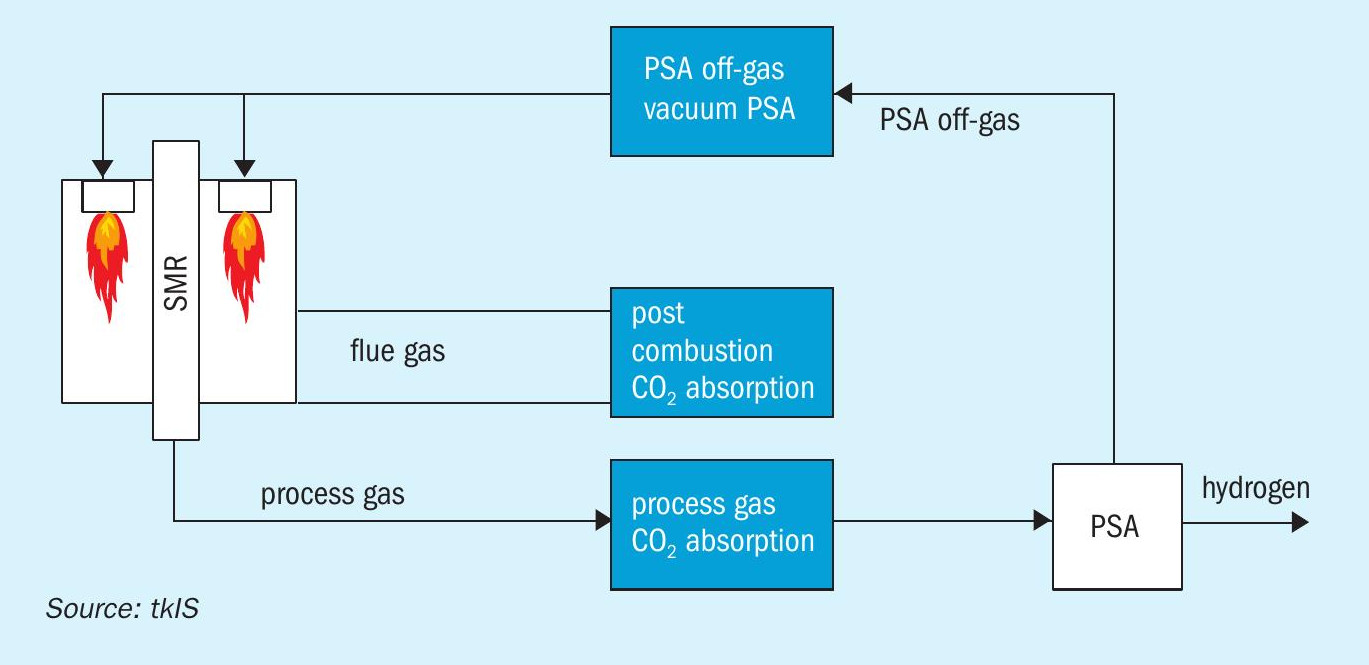
The conventional process for producing industrial scale hydrogen is steam methane reforming. A block flow diagram for a blue hydrogen SMR based process is shown in Fig. 2.
SMR is a simple process that has been well-proven over decades. The feed preparation section typically consists of a desulphurisation and feed purification section. It is followed by the steam reforming section. For liquid feedstocks (naphtha or LPG), it is recommended to use a pre-reformer. For gaseous feedstocks (natural gas, refinery off-gases), the installation of a pre-reformer is not required. Downstream of the steam reforming section the water gas shift reaction takes place where CO and water are converted to hydrogen and carbon dioxide. Typically, carbon dioxide is removed by an absorption unit installed downstream of the CO conversion. To meet the final hydrogen specification a pressure swing adsorption unit (PSA) is installed for final purification. The PSA off-gas is entirely used in the steam reformer to supply the heat required for driving the endothermic steam reforming reaction. Steam reforming plants are very efficient since energy available in the product and the flue gas are recovered entirely. In a SMR process CO2 is obtained from two sources:
- from the CO2 removal unit as an almost pure CO2 stream;
- from the combustion of PSA off-gas and make-up fuel and consequently as part of the flue gas.
- the PSA off-gas contains residual methane and CO which are converted to CO2 during combustion.
Autothermal reforming
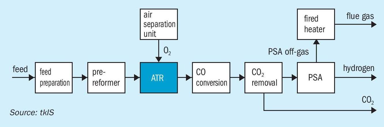
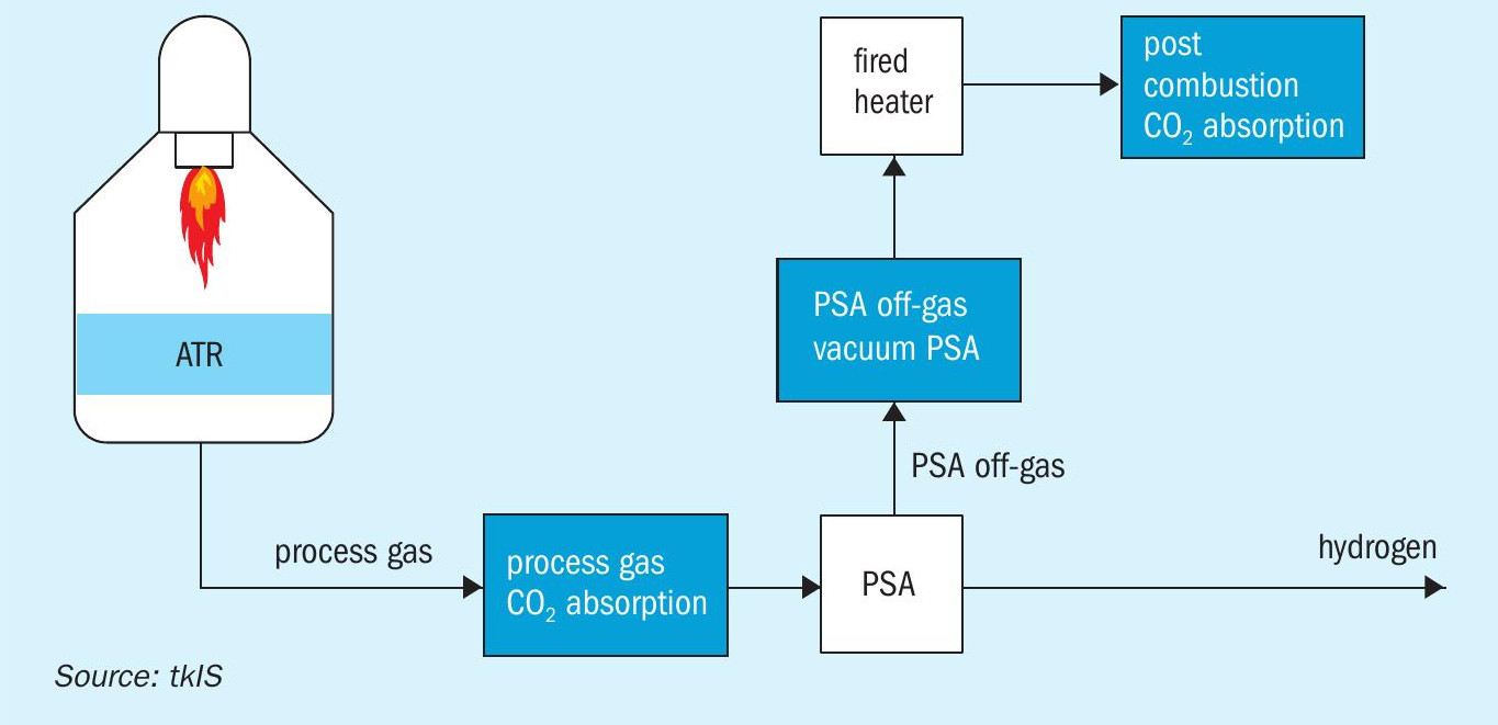
For large-scale, single-train hydrogen production, autothermal reforming (ATR) can be applied. A typical flowsheet of an ATR process is shown in Fig. 3.
The feed preparation section is followed by a pre-reforming section which is mandatory for ensuring robust and reliable operation of the ATR. In the pre-reformer all higher hydrocarbons are converted into a mixture of hydrogen, methane, carbon dioxide and carbon monoxide. The methane content downstream of the pre-reformer is substantial. Part of the residual methane is oxidised in the ATR, while the balance is reformed to generate hydrogen and carbon monoxide. The partial combustion of methane requires pure oxygen which can be provided by an air separation unit ISBL or via pipeline over the fence. It is not recommended to use combustion air for partial oxidation since the increased nitrogen content in the hydrogen product would be too high. Residual carbon monoxide is converted together with water into hydrogen and carbon dioxide. Downstream of the shift conversion, carbon dioxide can be removed by absorption and the final purification of the hydrogen takes place in a PSA. The PSA off-gas can be used in a fired heater to provide heat for internal preheating and to generate superheated high-pressure steam. In the ATR process, the fired heater is required to provide sufficient preheating for the feed/steam mixture and to superheat steam which is required within the process.
The ATR process is of particular interest for large, single-train hydrogen capacities, since it can be operated at high pressure and consequently, at low volumetric flow. In addition, the CO2 recovery is higher compared to a SMR process. This is attributable to the fact that the methane slip downstream of the ATR is much lower than downstream of an SMR. Hence, less methane is fired in the downstream fired heater than in the SMR itself, leading to lower CO2 emissions. A post combustion CO2 capture scenario is analysed below.
Carbon dioxide removal
In hydrogen plants, CO2 is produced via the water gas shift reaction in the steam reformer and the shift conversion as well as during combustion of PSA off-gas and make-up fuel. After separation, CO2 can be stored in long-term storage facilities, used in chemical synthesis (e.g. syngas, methanol, urea), as a feedstock for greenhouses or in the beverage industry. In a SMR or ATR process, CO2 can be captured from:
- the process gas downstream of the shift conversion and upstream of the PSA (pre-combustion);
- from the PSA off-gas (pre-combustion);
- from the flue gas (post combustion).
Fig. 4 illustrates the three options for CO2 removal for a typical SMR process. However, all of these options also apply to an ATR process scheme (see Fig. 5).
The separation of CO2 from the process gas combines the advantages of high gas pressure and medium to high CO2 concentration which facilitate the CO2 absorption. It also combines low capex and low opex. Due to a great degree of heat integration, opex are low. The entire heat required for regeneration of the loaded solution is supplied by low caloric waste heat from the SMR/ATR process and basically comes at no cost. In contrast, it increases the overall efficiency of the plant.
The CO2 from the PSA off-gas has the advantage of separating already concentrated CO2 which is typically around 50 vol-%. Vacuum pressure swing adsorption can be used to separate CO2 from the PSA off-gas. VPSA systems require mainly electrical energy and the potential for heat integration with the SMR/ATR plant is low. Hence, the additional electrical power cost translates into higher opex compared to absorption processes.
The separation of CO2 from the flue gas achieves very high overall CO2 recovery rates, since the CO2 generated from the feed which remains in the PSA off-gas and from the fuel are captured at the same time. However, the volume flow rate of the gas to be treated is high, while the CO2 concentration and the flue gas pressure are low, resulting in high capex.
thyssenkrupp hydrogen technologies
thyssenkrupp Industrial Solutions possesses all relevant technologies and experience to offer the entire spectrum of hydrogen production technologies, ranging from steam methane reforming and autothermal reforming to water electrolysis. In addition, tkIS has developed and implemented revamp concepts for SMR based hydrogen plants in which CO2 removal systems are installed as part of the revamp. tkIS has several operating references for blue hydrogen technology demonstrating the fact that blue hydrogen is a well-proven technology.
For revamping existing hydrogen manufacturing units, tkIS has developed a simple and robust concept to balance the heat in the SMR convection bank. The original design of the hydrogen plant considers a PSA off-gas with a substantial quantity of CO2 in the PSA off-gas. Removing CO2 from the process gas results in a CO2 lean PSA off-gas. Consequently, it has a tremendous impact on the combustion in the SMR and the heat balance of the waste heat train (convection bank). Partial recycling of flue gas is the key to overcome limitations in heat duties while reducing NOx emissions at the same time. The entire system can be installed while the plant is in operation and the two tie-ins can be connected in short time during a schedule plant shutdown.
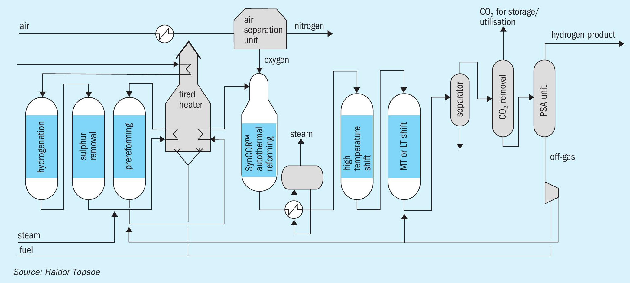
Topsoe SynCOR™ based blue hydrogen process
Topsoe offers well-proven steam methane reforming (SMR), combined with pre-combustion (high pressure) CO2 capture and/or post combustion (low pressure) CO2 capture technologies, for optimal blue hydrogen production with >90% CO2 capture rate. For high capacity (>200,000 Nm3 /h) blue hydrogen production, Topsoe offers its state-of-the-art SynCOR™ technology with pre-combustion (high pressure) CO2 capture technology as shown in Fig. 6. It provides low emissions and cost-effective production of “blue” hydrogen with >95% CO2 capture rate. These options can be either retrofitted to existing operating units or constructed as greenfield plants.
Casale blue technologies
Casale has developed efficient process schemes for blue ammonia and blue hydrogen production, based on technologies already available and referenced. Casale’s optimised process for blue ammonia production is able to compete in terms of opex and capex with processes without carbon sequestration.
A6000CC: Casale process for blue NH3
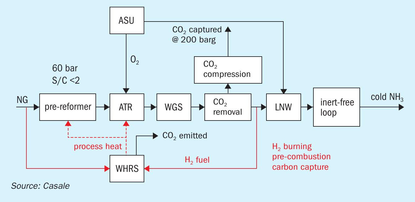
Adding a CO2 recovery section to the flue gas from a primary reformer in a standard ammonia plant transforms it into a blue ammonia plant, with very high CO2 sequestration (above 95%), but also adds significant capex and opex. In order to produce blue ammonia without these penalties, in 2017, Casale started to develop a new process scheme, named A6000CC (named derived from the A6000 series of Casale processes, conceived for big capacities of up to 6,000 t/d or more). A6000CC is based on a pure oxygen-blown autothermal reformer (ATR) front-end, operated at high pressure (60 bar) with a low steam to carbon ratio of 1.5, preceded by a pre-reformer. This reforming scheme was selected to achieve high capacity, high efficiency and to reduce the generation of high temperature heat, which is the main source of carbon emissions to the stack.
The produced syngas is further processed in a shift section and purified in a CO2 removal section and liquid nitrogen wash section to produce an inert-free makeup gas, which is compressed and sent to the synthesis loop to produce low-carbon cold ammonia. CO2 is captured in the frontend, compressed and sent to battery limits.
Process description and block flow diagram
A6000CC process has the following process sections, arranged as in Fig. 7:
- ASU;
- NG compression;
- desulphurisation;
- pre-reforming;
- O2 -blown ATR reforming with a single-burner design and 3D printed tip;
- shift conversion (HTS + LTS);
- process condensate stripping;
- enhanced CO2 removal based on amine wash (BASF Oase White);
- CO2 compression to 200 barg;
- synthesis gas drying;
- liquid nitrogen wash purification with methane pre-condensation;
- ammonia synthesis loop and refrigeration;
- steam generation;
- steam turbine generator (STG);
- waste heat recovery (WHR) section.
Natural gas is mixed with a small stream of hydrogen, a stream of methane recovered from the liquid nitrogen wash (LNW) unit and the flash gas from the carbon dioxide recovery (CDR) unit. The feed is compressed to about 66 barg and pre-heated to about 380°C in a dedicated coil of the waste heat recovery section.
The gas stream is deeply hydrodesulphurised with a dedicated HDS catalyst bed and two H2 S adsorption beds arranged in lead-lag to limit H2 S slip to below 0.1 ppm.
Deeply desulphurised gas is mixed with HPS process steam with a S/C ratio of about 1.5 and pre-heated to about 520°C in a dedicated coil of the WHR section. The pre-heated mixed feed is pre-reformed with an outlet concentration of about 6% H2 and with a substantial reforming of C2+ hydrocarbons and CO.
Pre-reformed gas is further pre-heated to about 650°C in a dedicated coil of the WHR section and delivered to the ATR. At the ATR burner, pre-heated pre-reformed gas at about 650°C is mixed with preheated oxygen at about 200°C with a suitable flowrate to achieve an outlet temperature of the ATR of about 1,000°C and a methane slip of about 2.2% wet (EOR) after the reforming catalyst bed.
Downstream of the ATR the heat recovery train consists of waste heat boilers (WHB) and steam superheaters (SSH), with an intermediate temperature of about 550°C between the exchangers and an outlet temperature of about 380°C, which generates HHPS steam at about 135 barg and is designed to mitigate the risk of metal dusting.
Reformed gas is delivered to the shift section comprising the HTS reactor and LTS reactor with enhanced heat recovery at high temperature.
Shifted gas is cooled down to about 64°C and process condensates are separated and pumped to the stripping section to remove by-products (methanol and ammonia) with HPS steam, producing a stripped condensate that is sent to the polishing unit. Shifted syngas is deeply purified in an enhanced CO2 removal section based on amine wash (BASF Oase White) and in a liquid nitrogen wash purification section with methane pre-condensation, to deliver an inert-free make-up gas.
In the CDR section, shifted gas is deeply decarbonised to a residual CO2 content of less than 5 ppm. Captured CO2 is compressed to 200 barg in a six-stage integrally geared compressor, with a DEOXO catalyst guard and a drying unit on the discharge of the third stage, to deliver CO2 at the requested purity level. The CDR section also produces a flash gas that is recycled back as feed gas.
In the LNW unit, methane is pre-condensed at about -183°C and recycled back as feed gas. The CO2 -depleted synthesis gas is further purified in the cryogenic wash column with liquid nitrogen flow. At the outlet of the cryogenic box three streams are separated: the purified inert-free make-up gas, a fuel gas used for heat and power generation and the methane-rich stream recycled as feed gas at the NG compressor suction (leading to about +1% CO2 capture rate contribution).
The H/N ratio of the purified inert-free make-up gas is adjusted with additional nitrogen compressed at about 53 barg and delivered to the suction of the syngas compressor. Make-up gas and recycle gas are compressed to about 170 barg and delivered to the ammonia converter(s) loaded with Amomax-Casale catalyst. The heat recovery includes BFW pre-heating and boilers to generate HHPS.
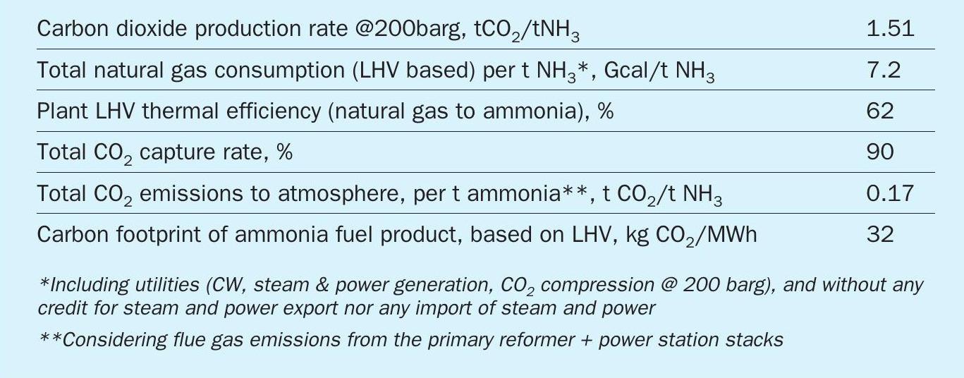
Key performance indicators for Casale blue ammonia are provided in Table 1.
The A6000CC process scheme can be applied to an existing plant through revamping, by modifying the reforming route to ATR. The front-end section downstream of the reforming and synthesis loop can be retained, and ammonia production capacity can be increased, improving the economics of the project. The energy efficiency has to be evaluated case by case.
H1000CC: Casale process for blue hydrogen
The A6000CC scheme can be easily modified to produce blue hydrogen instead of blue ammonia by eliminating the synthesis loop and liquid nitrogen wash sections.
H1000CC is a patented Casale process scheme based on a pure O2 -blown ATR front-end, operated at high pressure (generally 60 bar) with a low S/C (about 2.0), preceded by a pre-reformer.
The produced syngas is further processed in a shift section and purified in a CO2 removal section to produce a blue hydrogen product. CO2 is captured in the front-end, compressed and sent to battery limits. Installation of a pre-reformer permits reforming at a low steam to carbon ratio, which has significant debottlenecking effects on the whole section. The relatively small heating duty and overall plant efficiency are key factors to achieve a substantial reduction of the CO2 stack emissions compared to a conventional process.
Process description
The main units of the new Casale hydrogen plant are shown in the block flow diagram in Fig. 8.
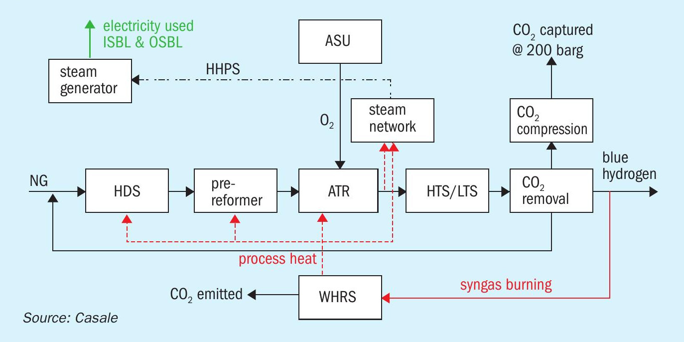
The main process sections are:
- ASU;
- NG compression;
- desulphurisation;
- pre-reforming;
- O2 -blown ATR reforming with single-burner design and 3D printed tip;
- shift conversion (HTS + LTS);
- process condensate stripping;
- enhanced CO2 removal based on amine wash (BASF Oase White);
- H2 purification unit (optional, according to the specification);
- CO2 compression to 200 barg;
- steam generation;
- steam turbine generator (STG);
- waste heat recovery section (syngas burning).
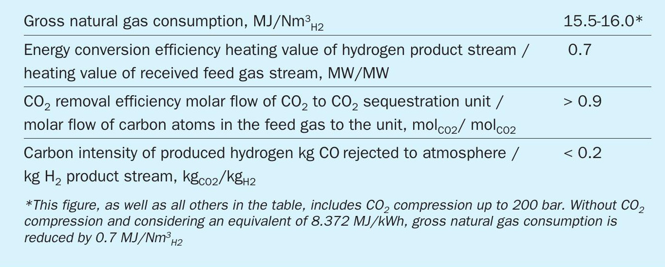
Key performance indicators for Casale blue hydrogen are provided in Table 2.
Key features of Casale design
The A6000CC and H1000CC processes offer the following process advantages:
- easy scalability (no tubular reformers) to high single-train capacities, lowering capital and operating costs, and improving the plant’s operability and reliability, whatever the feedstock;
- minimisation of fired duty for process purpose as flow is minimised (low S/C ratio);
- high total carbon capture with one single CDR in the process (no CDR on flue gas);
- for H1000CC, the possibility to deliver H2 product up to 55 bar.
For high production capacities, the benefit of having one single line instead of multiple lines are:
- lower total investment cost;
- less plot space,
- fewer operators.
Plant reliability is one of the main factors for hydrogen plant profitability. Achieving plant targets strongly depends on having a reliable design that is flexible, efficient and economical.
According to Casale strategy, safety is one of the major plant design targets and a reliable design is the most crucial factor that makes it possible to achieve this goal.
Safety in the design of petrochemical process plants primarily relies on the application of various codes of practice or design, which are based on the wide experience and knowledge of professional experts and specialists in the industry. That is backed up by the experience of local plant managers, engineers and operators, who have direct experience in the relevant plant operation.
Casale ATR
Casale ATR is a key technology in both A6000CC and H1000CC processes. In autothermal reforming a catalytic bed is installed within a refractory-lined pressure vessel to bring the methane steam reforming reaction as close to equilibrium as possible.
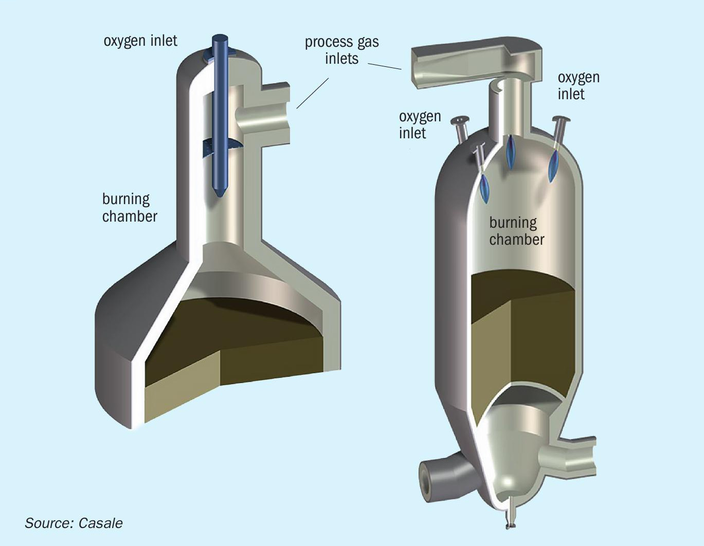
The Casale autothermal reformer (ATR) design is conceptually very simple. The oxygen stream is introduced at high velocity axially at top of the combustion cylindrical chamber. The partially reformed gas is introduced from one side at the top of the cylindrical chamber, before the burner tip, perpendicular to the burner. The high velocity of the oxygen causes mixing between the two streams and the combustion reaction takes place instantaneously after mixing. A circular distributor with a small pressure drop is provided upstream the burner in order to obtain a uniform flow of natural gas before its mixing with the oxygen.
The fluid-dynamic flow field inside the combustion chamber is designed in order to protect the refractory lining from the high temperature core of the flame, preventing hot spot on the lining surface.
The gas recirculation that builds up inside the combustion chamber shield the refractory lining from the flame hot core, which can reach temperature as high as 2,700°C, keeping its surfaces well under 1,400°C, i.e. well below the refractory maximum operating temperature.
The water path inside the burner tip ensures uniform cooling of all the burner walls. In particular, the heat transfer coefficient of the water flow has been enhanced corresponding to the tip that is close to the flame.
Fig. 9 shows the Casale single-burner and multi-burner ATR design.
Casale uses CFD tools when designing its burners to simulate the flow and temperature fields inside the combustion chamber and within the burner body, taking into account the strong correlation between turbulence and chemical kinetics. The CFD results are used together with thermal and FEM analysis of the burner’s solid surfaces, which are essential to understand and optimise the burner design. These calculations are confirmed by industrial experience. Casale’s approach addresses most of the common problems relating to reformer burners: poor mixing, soot formation and overheating of the surfaces exposed to the flame.
The main features of Casale’s pure oxygen autothermal reformer burner design are:
- Good mixing between oxygen and natural gas, with an almost uniform field of temperature, velocities and composition at the catalytic bed entrance:
– a better equilibrium approach due to almost uniform temperature and composition at the catalytic bed inlet.
– a shorter flame; avoiding the impingement of the flame on the catalytic bed, thus resulting in longer life of the catalyst, better performance and no pressure drop increases due to sintering/milling.
- Soot-free operation
- Flexible operation, allowing good burner performance over a wide range of flow rates.
- Low temperature of the reformer refractory lining.
- Water-cooled burner tip in order to ensure several years of safe operating life with low temperature of the burner surfaces exposed to the flame:
– no plant shutdown related to burner failure
– proven trouble-free operation
– up to eight years of proven operation with a single Casale burner
- Flame stability.
Soot formation has been studied in depth by Casale thanks to a vast amount of information gained from a long series of experiments conducted on a demonstration size pilot burner in recent years. Thanks to this unique experience, Casale can predict with absolute confidence what operating conditions may lead to soot formation and indicate how to operate to avoid it.
Operating experience
Casale has experience in the design of ATR reactors for both ammonia and methanol production and for both two-step reforming and pure ATR (with coke oven gas) configurations. Casale has several referenced ATR reactors for methanol production in operation or scheduled for start-up, with capacities ranging from 350 to 7000 t/d. At present there are nine units in operation, including a 5,000 and a 7,000 t/d methanol plant.
The first Casale ATR application was for a 350 t/d methanol plant with two-step reforming. This unit has been operating continuously since its start-up in October 2001.
The burner was operated over a wide range of flow rates, from 20% to 110% of the design load, without performance losses or any other operational problems.
Another Casale ATR reactor in operation is installed in a two-step reforming 1,350 t/d methanol plant. The unit was started-up in May 2004 and has been operating since then without any mechanical or process issues. The burner is usually operated over a wide range of flow rates, from 30% to 115% of design load, always providing good performance according to expectations in terms of pressure drops and methane slip.
The regular turnaround inspections of the ATR reactor allowed for the verification of the effectiveness of the cooling water system installed in the burner tip. After several years of operation at high temperatures, the penetrating liquid test showed no traces of cracks due to thermal fatigue of the burner tip.
The good condition of the burner tip and the absence of cracks can be ascribed to both the efficient cooling provided by the cooling water system and the accurate fluid dynamic design of the combustion chamber.
The ATR reactor turnaround inspections also showed no evidence of flame impingement on the combustion chamber/vessel refractory lining or on the target bricks installed on top of the catalytic bed. No traces of catalyst sintering or ruby formation were detected during catalyst replacements.
Two ATRs designed by Casale are in operation in methanol plants in Iran. Kaveh (H2 +CO ª 630 kNm3 /h), the largest methanol plant in the world and Bushehr (H2 +CO ª 475 kNm3 /h).
References