Sulphur 396 Sept-Oct 2021
30 September 2021
Drying out acid condensation
CORROSION IN SULPHURIC ACID PLANTS
Drying out acid condensation
Corrosion is one of the most critical aspects regarding sulphuric acid plant lifespan. One important cause of corrosion in sulphuric acid plants is acid condensation from the process gas due to inadequate drying. E. Almeida, B. Ferraro, N. Clark, V. Machida and V. Sturm of Clark Solutions discuss this problem and how it can be avoided with proper tower and internals design.
Adequate air/gas drying is critical for the long-term health of a contact sulphuric acid plant. A proper drying stage guarantees a significant increase in plant equipment lifespan as well as lower maintenance costs. Corrosion is one of the main maintenance and safety subjects in a wide variety of industrial processes, in sulphuric acid production it is, by far, the most important one.
An efficient humidity removal process minimises acid condensation on plant cold surfaces, a condition that is frequently found, mostly in heat exchangers such as gas-gas and economisers, but also in ducts and other surfaces. Drying tower acid carryover has also been a concern for damage in furnaces and to catalysts.
Proper selection and specification of drying tower internals is critical for adequate control of air/gas moisture content to minimise or eliminate condensation induced corrosion conditions.
Drying process
Drying sulphuric acid plant feed gas is key for minimising the risks of acid condensation on cold surfaces.
Humidity removal takes place in the drying tower. In a sulphur burning plant, operation of the drying tower can be either pressurised or under vacuum in respect to the blower position, whereas in regeneration and metallurgic plants the blower is positioned after the drying tower.
Humid gas/air enters the bottom of the tower and contacts concentrated sulphuric acid which absorbs humidity. The gas-liquid contact takes place on venturis or ceramic packed beds. Before leaving the tower the gas passes through a mist eliminator to remove any entrained liquid, while acid is removed via a nozzle at the bottom of the tower. Thus, the drying process consists of two main stages: mass transfer and mist elimination.
Mass transfer stage
The mass transfer stage basically consists of irrigating sulphuric acid through a liquid distributor over the ceramic packed bed.
Due to its hygroscopic characteristic, when on close contact with air the acid removes its moisture. This process slightly dilutes the acid that exits at the tower bottom.
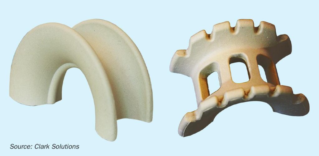
Ceramic packing is responsible for providing the contact surface for the gas and liquid phases. Increased packing specific surface area (m2 /m3 ) results in more contact and, alongside higher packing heights, results in a higher total mass transfer area. A proper balance between the provided mass transfer and pressure drop is required for adequate drying without hindering plant capacity. Advanced geometries may increase or maintain surface area with no pressure drop increase.
Another fundamental aspect is the void fraction. Lower values translate into higher pressure drops, resulting in higher energy consumption. Fig. 1 shows standard saddle packing on the left and a low pressure drop alternative on the right, which offers the same surface area but with higher void fraction and lower pressure drop.
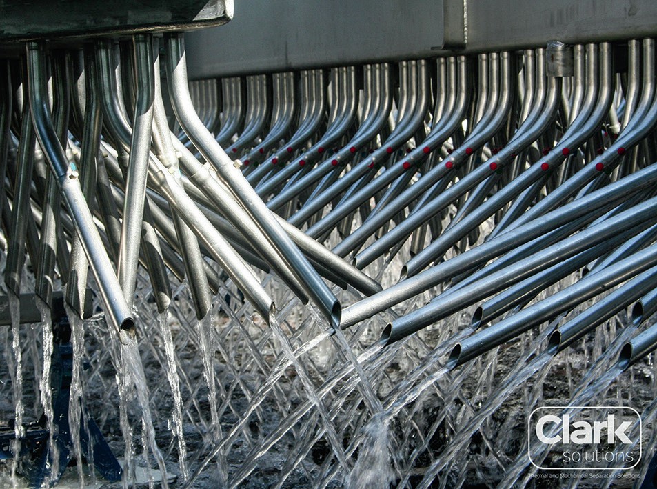
At the top of the packing, the liquid distributor receives acid from the pump and distributes it in a homogeneous way over the tower cross sectional area, aiming for the promotion of sufficient wettability to guarantee maximum liquid film area flowing over the packing surface. Proper acid distribution not only guarantees effective mass transfer, but also allows for reduced packing height design, lowering capital and operating costs, while still maximising mass transfer and air/gas dryness.
Several types of liquid distributor are available, and selection depends on the specific set of conditions. The most common liquid distributor types are: pipes and troughs with downcomers (Fig. 2).

At the bottom of the packing, the support is responsible for all packing, acid holdup and sometimes the liquid distributor, while minimally affecting gas flow to maintain proper gas distribution and low pressure drop. The most common packing support types are auto portable domes, ceramic bars, or metallic grids. Low pressure drop transition packing such as cross-partition rings are also used and provide homogeneous gas flow from the packing support.
Mist elimination stage
Contact between gas and liquid in the mass transfer stage promotes dryness at the expense of liquid sulphuric acid entrainment. The closer and more turbulent the contact between the liquid and gas phases, the more mist entrainment is to be expected. This liquid mist needs to be collected before the gas outlet to avoid upstream corrosion and damage.
In contrast to an absorption tower, there is no chemical reaction in the drying tower, so generated mist particles are usually large, in the range of five microns and larger (an exception to this is in spent acid and metallurgical plants where the presence of smaller particles is frequent, especially when electrostatic mist precipitators are operated above design conditions or suffer performance upsets). Wire mesh mist eliminators, plain metal for conventional sulphur burner drying towers or polymer co-knitted metal for spent acid and metallurgical plants, provide sufficient mist elimination for drying towers.
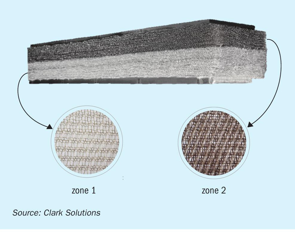
In order to comply with ever more demanding requirements from acid plant operators, modern wire mesh mist eliminators, such as Clark Solutions Maximesh® , are designed and built with multiple operating zones (Fig. 3). As a minimum:
- A heavy duty gas impingement zone situated at the bottom of the pad removes the bulk of the liquid and is built in such a way that it will resist mechanical stress.
- A high efficiency, fine mist polishing collection zone at the mesh pad upper section collects fine mist guaranteeing maximum performance.
- he lower zones are usually built with a mesh geometry that will favour drainage and a wire tensile strength that will resist to mechanical stress.
Upper section collection layers use a finer wire and a geometry that increases collection efficiency. In special cases where very high particle collection efficiency is required, polymeric materials with very high filament count and very small filament diameters can be specially knitted to the wire improving collection efficiency to levels as high as 100% for particles of two microns and above.
Materials such as chemical resistant fibreglass, PTFE or other polymers can be used to increase the mist collection efficiency in the small particle size range. This comes at the expense of some extra pressure drop, that can increase by 10-25 mm w.c. for plain metal pads to 50-75 mm w.c. for co-knitted pads.
The proper wire mesh configuration to be used in a plant is dependent upon many factors. Each configuration is used to address different plant characteristics.
Humidity effects on the sulphuric acid plant
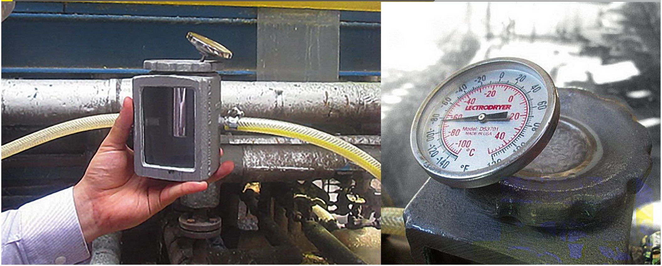
Once the drying tower is in service, the humidity removal efficiency can be easily checked by a very simple dew point test downstream from the drying tower.
This test can be carried out using a device such as the Lectrodryer dew cup apparatus, illustrated in Fig. 4.
While feeding dry gas to the device, using the tower’s positive pressure or with the support of a vacuum pump in negative pressure towers, dry ice and acetone are placed on the inner side of the device’s polished cup, together with a thermometer. As the acetone and dry ice evaporate, heat is removed from the mixture and the temperature drops continuously. As it decreases, the polished cup outer surface cools. As it cools, one must observe the sight glass and the cup outer surface. When the smallest trace of condensation is observed, the dew point temperature displayed on the thermometer is registered. This test is usually precise to within a 2-3°C range.
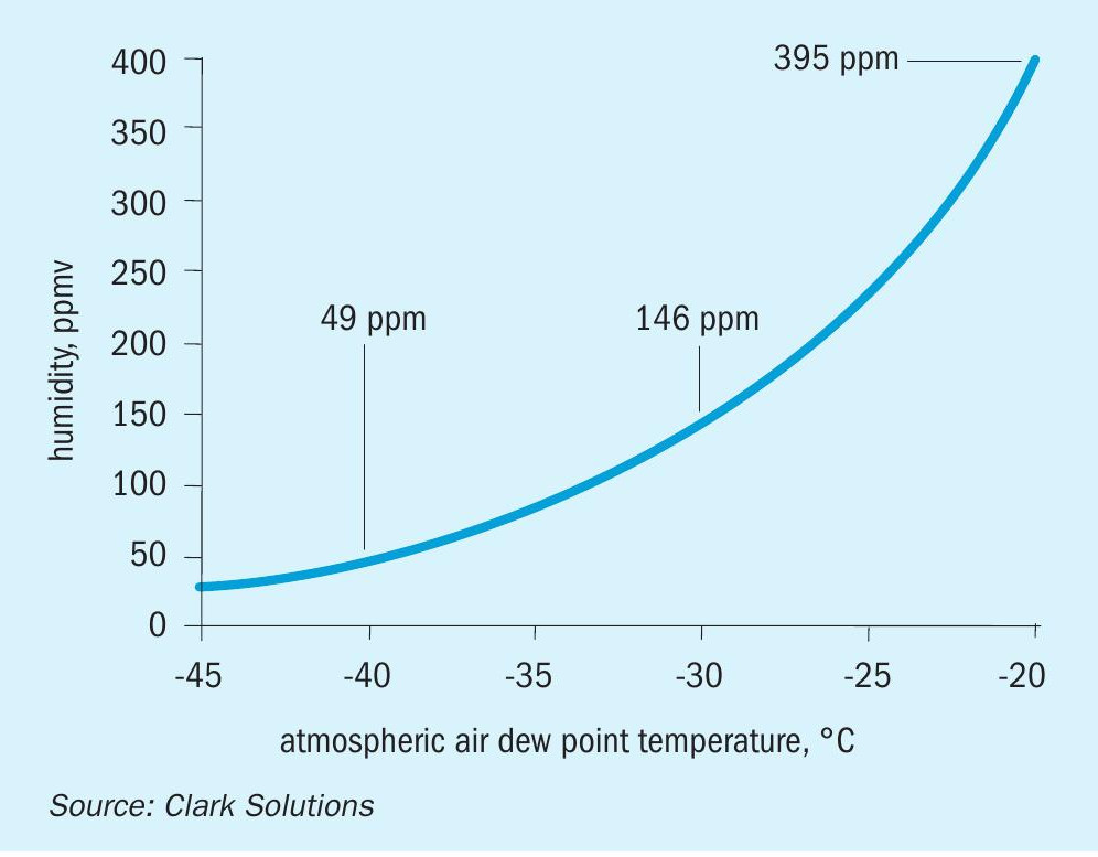
It is possible to calculate the gas residual water concentration with this temperature using the plot on Fig. 5.
A dew point of around -40°C is an indication of very good air dryness. Dew points above -30°C are cause for concern, particularly on those plants with low temperature economisers and other low tube wall temperature devices.
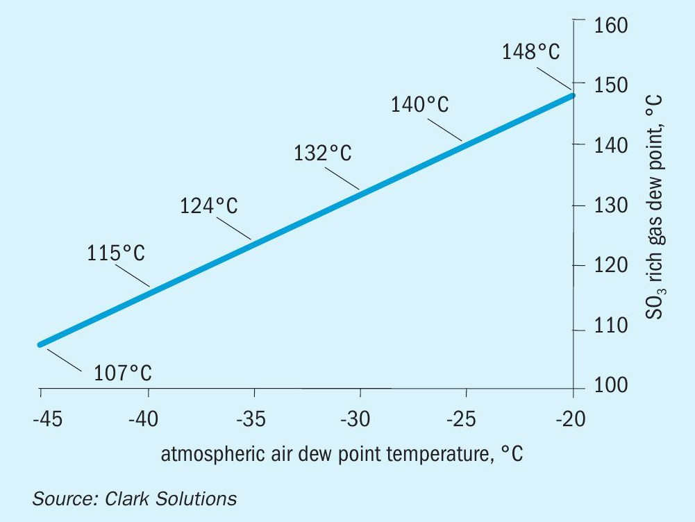
Downstream in the plant, due to the chemical reactions involved, SO2 and SO3 are present in the gas mixture. The SO3 rich gas dew point temperature is considerably higher than the atmospheric air dew point temperature and the condensed liquid is sulphuric acid.
Fig. 6 shows that in an environment rich in SO3 the higher humidity in the process gas (higher atmospheric air dew point temperature) results in higher temperatures from which the acid starts to condense.
Note that the plot does not consider SO3 composition, since beyond a certain concentration value, the SO3 does not significantly change the dew point temperature due to its excess. The condensation temperature can vary depending on fouling or the presence of particulates.
It is important to notice that condensation generally occurs on equipment surfaces, so the condensing temperatures displayed are wall temperatures, not the bulk gas temperatures. Wall temperatures are an average value between the cold and hot side temperatures. Depending on the process fluids, the wall temperature will be closer to one of the sides. For instance, in an economiser, the cold side fluid is liquid water, which has a heat transfer coefficient considerably higher than the gas side, thus the tube wall temperatures will be close to that of water instead of that of the bulk gas.
Supposing, for instance, a plant with an insufficient drying stage, results in a dew point of -20°C. If there are any surfaces below 140°C, there will be sulphuric acid condensation, which will promote corrosion. These lower temperatures can be found in economisers, gas-gas heat exchangers or low-pressure boiler tube walls.
If a 200°C process gas is cooled by 120°C water in an economiser, it can be assumed that some regions of the gas-side tube wall will have a temperature of approximately 140°C, which is cold enough to promote condensation for the above-mentioned example.
Achieving an adequate drying stage
Good engineering practices can be followed to achieve both adequate humidity removal in the drying tower and sufficient mist elimination.
Mass transfer good practices
Mass transfer phenomena depend on the liquid to gas ratio, irrigation rate and density and packing height and geometry.
Regarding liquid to gas ratio, tower diameter is selected by achieving a proper gas velocity for the free cross-sectional area. The gas velocity must allow a reasonable pressure drop on the packing bed, while maintaining complete wettability of the packing without entraining much liquid. Liquid flow rate is selected respecting a proper range for irrigation rate. Higher irrigation rates enhance the drying capacity until equilibrium is achieved but require more pumping and adequate distributor selection. On the other hand, operating with low irrigation rates could jeopardise the mass transfer and create dry packing sections promoting gas channelling.
Liquid irrigation density is a measure of how many pour points the liquid distributor offers over the packing bed top by unit of area. It is important for homogeneous distribution and to avoid gas channelling. In addition to the number of pour points, proper pour geometry is also of fundamental importance.
Different liquid distributors offer distinct maximum irrigation densities. For instance, for cast iron distributors, due to natural manufacturing constraints, the maximum irrigation density is typically 15 points per square metre of cross-sectional area. Clark Solutions’ MaxiFlow® trough and downcomer liquid distributors are usually manufactured in CSX® high silicon stainless steel or other corrosion resistant alloy. The materials are more workable and weldable, allowing for construction geometries that improve distribution efficiency. MaxiFlow® distributors have a wide range of geometries that can achieve irrigation densities as high as 1,000 points per square metre of tower cross sectional area. MaxiFlow® trough and downcomer liquid distributors can achieve irrigation densities of several dozen pts/m2 .
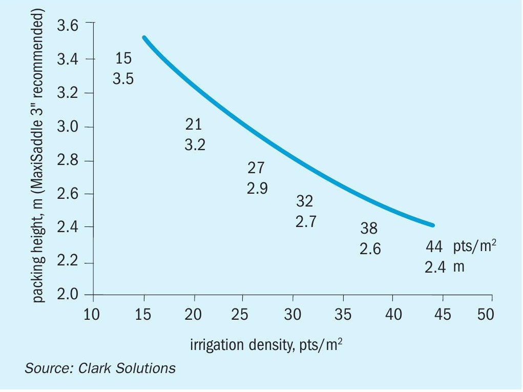
High irrigation densities promote better homogenisation of the liquid distribution demanding a lower packing height as illustrated by Fig. 7. All liquid distributors could be adequate if compatible packing height is offered, however low irrigation density demands a higher packing bed.
“Adequate air/ gas drying is critical for the longterm health of a contact sulphuric acid plant
Mist elimination good practices
Apart from the mist eliminator design, adequate mist elimination depends on the liquid distributor type, liquid distributor free cross-sectional area, spray catcher availability and mist eliminator installation.
A good mist eliminator prevents liquid sulphuric acid from corroding equipment and materials downstream of the drying tower.
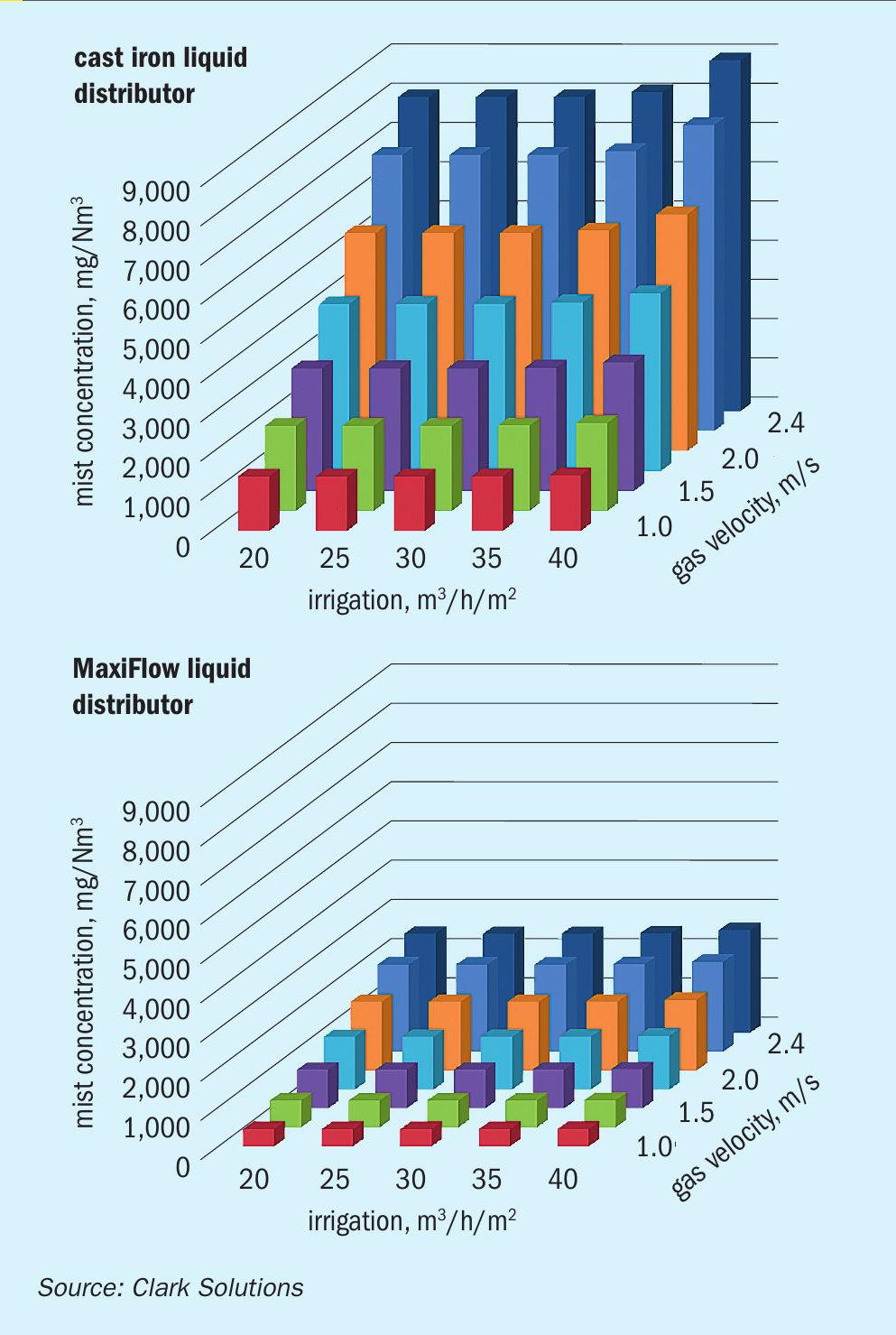
Poorly designed or old-style distributors (such as cast iron distributors) considerably reduce the passage of free gas around the distributor, creating a high velocity region at the packing top which increases mist generation that must be handled by the mesh pad mist eliminator. Proper distributor designs such as MaxiFlow trough with downcomers offer a large free cross-sectional area, minimising velocity in the distributor pouring area and minimising mist generation. This comparison is illustrated in Fig. 8.
A spray catcher section of at least 250 mm of height also minimises mist generation. Downcomer ends are buried into this section of 38 mm or 50 mm diameter saddles that prevent some of the mist from being entrained.
Finally, good mist eliminator installation is essential to prevent any possible gas channelling, avoiding liquid sulphuric acid carryover.
Conclusions
Adequate internals design and selection facilitates the achievement of dew point temperatures in the region of -40°C (sometimes up to -60°C), enough to minimise acid condensation on cold surfaces such as gas-gas heat exchangers, economisers, and others.
Clark Solutions uses optimisation studies for sulphuric acid tower internals, offering packing supports, random packings, special alloy liquid distributors and mist eliminators, designed to guarantee the best possible conditions to enhance plant lifespan.