Sulphur 397 Nov-Dec 2021
30 November 2021
Sour water stripping gas processing options
SOUR WATER STRIPPING
Sour water stripping gas processing options
M. Rameshni and S. Santo of RATE discuss different sour water stripping gas processing options, depending on contaminants in the sour water streams and site-specific requirements.
In refineries, sour water is produced from different processes and units e.g. from naphtha and diesel hydrotreating and the delayed coker units. The sour water stripper removes hydrogen sulphide (H2 S) and ammonia (NH3 ) from the sour water generated in the refinery. Steam, generated in the reboiler, heats the water, and strips the H2 S and NH3 from the water.
The sour water streams produced by distillation and delayed coking units are often referred to as phenolic water, while the sour water stream produced by the hydrotreating units are often referred to as non-phenolic water.
The sour water from delayed cokers contains H2S, NH3 , and CO2 , water, phenol and cyanide. The sour water from the hydro-treater contains H2S, NH3 , CO2 and water.
In other words, in addition to H2S, NH3 , and CO2 , phenolic sour water may also contain so-called heat stable salts (HSSs), hydrogen cyanide, and phenols. The presence of these components can adversely affect the ability to strip ammonia and H2S.
Due to the solubility of ammonia in water, and other impurities, the design of the phenolic sour water stripper is different from the non-phenolic sour water stripper:
- higher reboiler duty;
- more trays and higher efficiency trays;
- phenolic treated water cannot be used as process water as it would damage the hydrotreater catalyst;
- the overhead system of phenolic and non-phenolic SWS may be designed differently to prevent the buildup in the SWS.
The phenol and cyanide in the delayed coker sour water are highly soluble in water and very difficult to strip out. The treated water still contains some of these components and should not be recycled to the hydrotreater because it will damage the hydrotreater catalysts and cause corrosion. The sour water from the delayed coker is therefore treated separately in a separate SWS. No reflux is recycled to the tower to prevent the buildup of phenol and cyanide. The tower overhead is condensed in the overhead and is usually routed to the sulphur recovery unit (SRU) for further treatment.
In the design case, the stripped water must comply with the following specifications:
- Maximum H2 S content (wt ppm): <1
- Maximum NH3 content (wt ppm): 10
For a grassroots refinery design, in most cases the refinery would have a phenolic and non-phenolic sour water stripper, where the overhead gas is sent to the SRU; non-phenolic water from the bottom of the SWS tower can be recycled to the hydrotreating unit, but phenolic water from the tower is sent to another unit for further treatment.
Historically, it has been normal industry practice in most cases to process the sour water in a single column the so-called sour water stripper. The overheard of the SWS containing the sour gases (SWS gas) is sent to the thermal reactor of the sulphur recovery where a high intensity burner is used for the destruction of NH3 , H2 S, hydrocarbons, phenol, and cyanide. It is anticipated that with proper design the combustion temperature of the burner will be adequate for complete destruction of impurities such as phenol, cyanide, and heavy hydrocarbons.
The so-called treated water from the bottom of the sour water stripper is sent to the water treatment system for further processing.
In some refineries, especially in the US, a two-stage sour water stripper is used to separate the ammonia from the H2 S. The recovered H2 S is sent to the SRU, and the recovered ammonia is sold to the fertilizer industry to produce nitrogen fertilizers. The purity of the ammonia from the old technology two-stage sour water stripper was not very high but met environmental regulations.
Different sour water stripper options are listed below:
- single-stage sour water stripping, non-phenolic water;
- single-stage sour water stripping phenolic water;
- two-stage sour water stripping in series for phenolic water to strip phenol and cyanide;
- SW-MAX, two-stage sour water stripper to produce pure NH3 and pure H2S.
In the first option, the H2S is sent to the sulphur recovery unit and the ammonia is sent to the fertilizer unit. In the second option, the H2S is sent to the sulphur recovery unit and the ammonia is sent to the incinerator.
Single-stage SWS
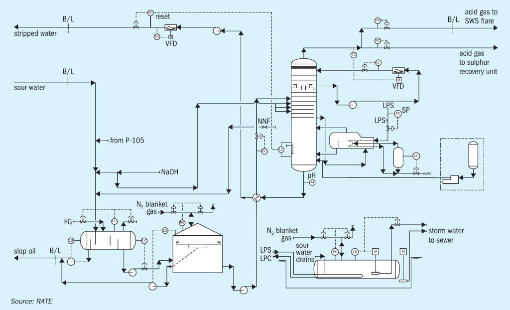
Sour water is collected from all of the units in the facility and sent to a dedicated vessel. Sour water is received in the sour water feed drum in which water and oil are separated. Caustic NaOH is injected into the sour water line to the sour water feed drum. Any flash gas generated goes to the tail gas incinerator. The slop oil pump transfers the recovered oil to the closed drain system on high level in the oil compartment of the sour water feed drum.
The sour water tank feed pump transfers the sour water from the sour water feed drum, under level control, to the sour water feed tank. The tank is a cone-roof tank with an oil skimmer attached to an internal floating roof. It is designed for a 72-hour residence time to minimise the effects of fluctuations in the sour water composition. The tank is also provided with nitrogen blanketing above the floating roof and a H2 S analyser of the nitrogen space. Skim oil separated out in the oil skimmer is sent, via skim oil pumps to the discharge line of the slop oil pumps.
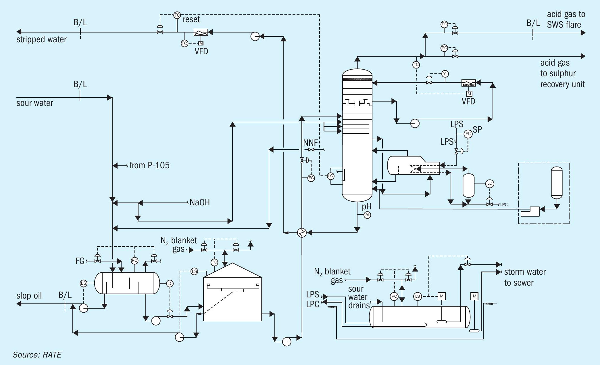
The sour water stripper strips the sour water feed from the sour water feed tank. The sour water feed is first pumped with sour water stripper feed pumps and then preheated in the stripper feed/bottoms exchanger by the hot stripped water from the column. To avoid corrosion due to flashing, the feed temperature is limited to 95°C.
The stripper has a lower stripping section, and an upper pumparound section, which serves as a contact condenser for most of the stripping steam. The pumparound pump recirculates water from the top chimney tray back to top tray via the pump-around air cooler under flow control. Excess pumparound water continuously overflows the chimney tray as internal reflux. The pumparound cooler is regulated to maintain acid gas vapour temperatures no lower than 75°C to avoid gas-phase deposition of solid ammonium bisulphide (NH4 HS). The stripped gas goes to the SRU.
Low pressure steam is directly injected into the bottoms of the sour water stripper for stripping. An ammonium polysulphide package also injects ammonium polysulphide into the bottoms of the sour water stripper.
Hot stripped water is initially cooled by heat exchange with the stripper feed in the feed/ bottoms exchanger. It is then pumped by the SWS bottoms pump for further cooling in the recovered water cooler. The bottoms flow is automatically adjusted to maintain a constant liquid level in the stripper. The cooled stripped water is returned to the unit it originated from (delayed coking unit or hydrotreating unit) outside of the battery limit. Fig. 1 shows a single-stage sour water stripper.
SWS-MAX 2-stage SWS for pure NH3 and H2 S
SWS-MAX is a proprietary two-stage sour water stripper design by RATE.
H2 S stripping
From the feed tank, the degassed sour water is pumped to the two-stage SWS plant, where it is heated by feed bottoms exchange and fed to the acid gas or hydrogen sulphide stripper. This stripper is a steam-reboiled distillation column. The hydrogen sulphide, which is stripped overhead, is of high purity and an excellent feed for sulphur plants. It contains negligible ammonia and, because the plant feed has been degassed, only traces of hydrocarbons. It does, however, contain any carbon dioxide that is present in the feed.
Ammonia stripping
The hydrogen sulphide stripper bottoms stream, containing all the ammonia in the feed and some hydrogen sulphide, is fed directly to the ammonia stripper, which is a refluxed distillation column. In this column, essentially all ammonia and hydrogen sulphide are removed from the water, which leaves as the column bottoms stream. After exchanging heat with the hydrogen sulphide stripper feed, this stripped water is cooled and sent off-plot for reuse or treating. The ammonia and hydrogen sulphide stripped from the water in the ammonia stripper are passed through an overhead condenser and are partially condensed.
H2S absorption
The purpose of the H2S absorber is to remove any additional H2S from the rich NH3 stream and recycle it back to the system to ensure the incineration stack complies with SO2 emission regulations.
Ammonia incineration
Ammonia can be sold as a liquid to local fertilizer companies or burned in the incinerator.
For some plants, ammonia recovery may not be desired or may be uneconomical. In such cases, the ammonia product can be incinerated, either directly off the reflux drum or after being scrubbed with water to reduce the hydrogen sulphide content. Alternatively, it may be further purified and recovered to produce either anhydrous or aqueous ammonia suitable for sale or for further processing.
Key features of WSW-MAX are:
- Stripping the mixture of H2 S and NH3 in a first stripping distillation column to obtain a rich H2S vapour, which flows, to the sulphur recovery unit. The bottom of the stripping column contains rich NH3 which is processed in the second tower.
- Stripping the rich NH3 in a second stripping distillation column to obtain rich NH3 vapour, it is purified further in the H2 S absorber to remove any residual of H2 S before sending it to the ammonia-burning incinerator or to the fertilizer unit.
- The overhead of the H2S absorber through the knockout drum is pure rich NH3 . The bottom of the H2 S absorber and the knockout drum containing H2 S is recycled to the first distillation tower H2S stripper through the feed tank.
- The advantage of the two-stage column design is the separation of H2S and NH3 into different product streams. The ammonia stream can be combusted without producing significant SO2 , or it can be purified and sold as feedstock. Likewise, the purified H2 S can be directly used as a feedstock for a sulphuric acid plant. Besides beneficial uses, diverting NH3 away from the SRU can improve the performance of the SRU. Ammonia can cause operating problems such as catalyst deactivation and equipment plugging in the SRU. In addition, a higher flame temperature is required to fully destroy NH3 , leading to higher COS and CS2 formation and subsequently lower sulphur recoveries.
- The size of the SRU can be reduced or the throughput of an existing unit can be increased since the extra air required to burn the ammonia, as well as the ammonia itself, is eliminated from the feed.
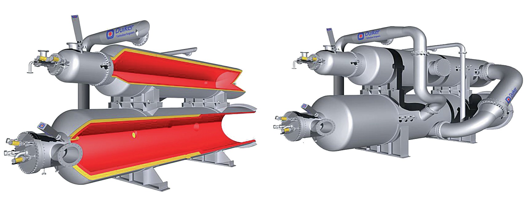
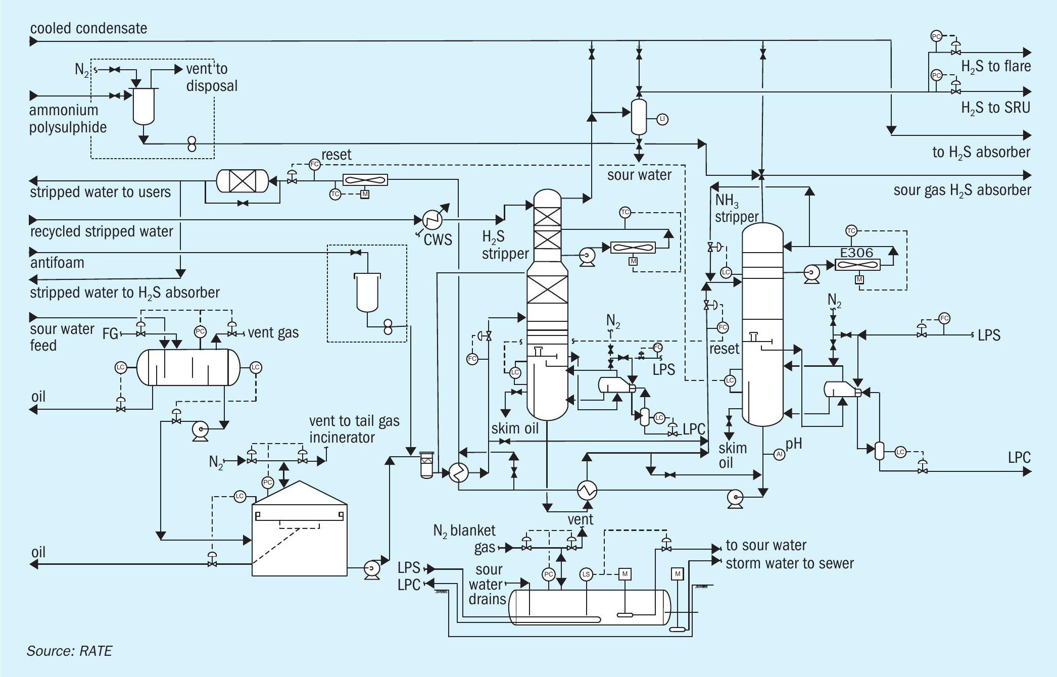
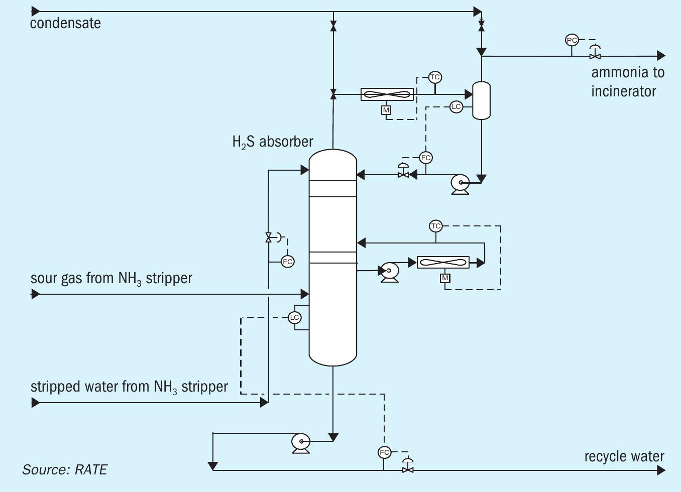
Fig. 2 shows an example of a special ultra-low NOx ammonia burning incinerator design by Duiker.
Figs 3 and 4 show the two-stage SWS-MAX proprietary design by RATE.
The H2S absorber removes all residual H2S to produce pure ammonia, free of H2S, that can be incinerated compliance with SO2 emission regulations. SWS-MAX differs from other technologies that require having caustic scrubbing to meet environmental regulations.
If the ammonia stream is to be incinerated it is sent to the incineration section, comprising a forced draft incinerator with heat recovery. The burner is a proprietary design to manage ammonia burning without any NOx formation. The ammonia will be dissociated in such a way to keep NOx at a very low level and to comply with environmental regulations.
The flue gas is cooled in a waste heat boiler by generating high pressure steam. The high-pressure steam along with the excess high-pressure steam from the SRU is superheated in the superheater coil of the incinerator waste heat boiler before being exported to the high-pressure steam header. The incinerated flue gas is routed to the stack.
Case studies of recent RATE projects
Case 1 – SRU capacity expansion
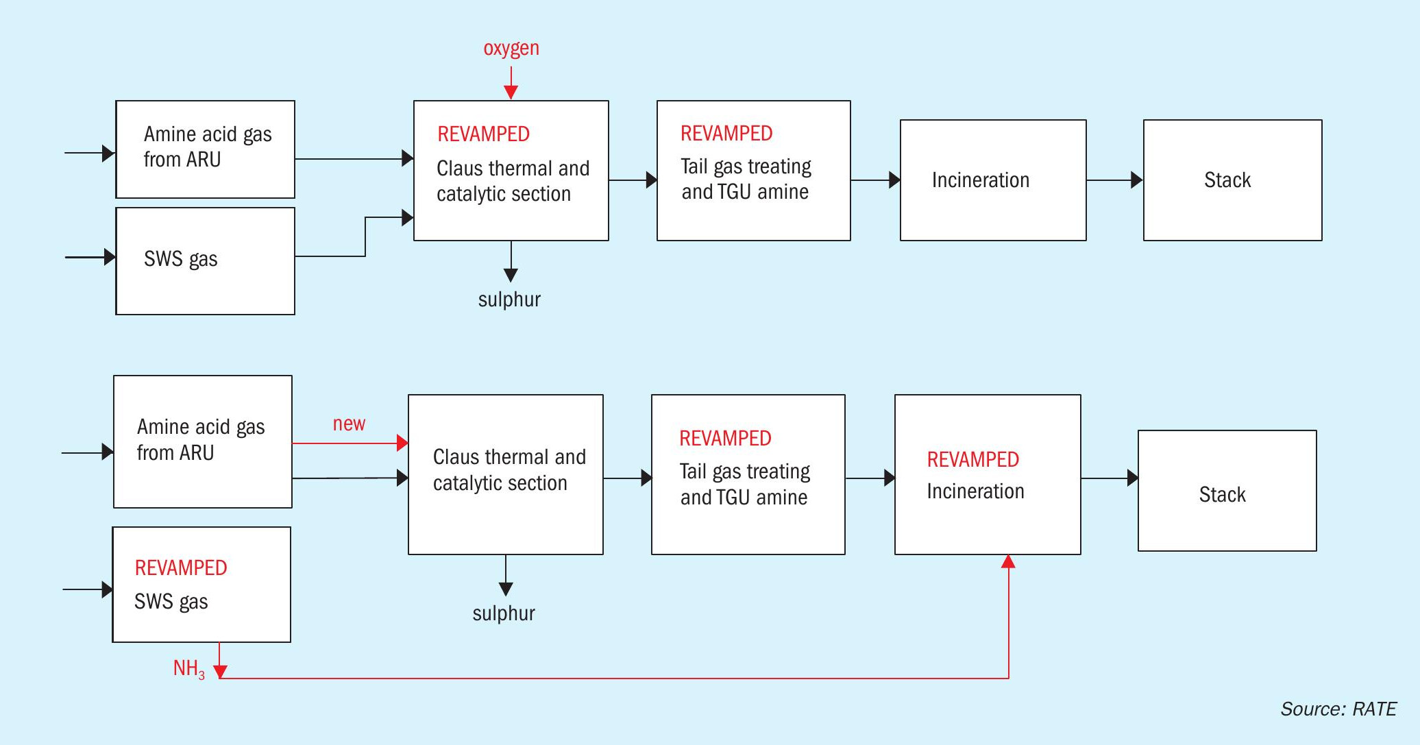
In this project, the customer had an existing sulphur recovery unit treating amine acid gas and the sour water stripper gas from the sour water stripper and, due to an expansion of the refinery, the SRU capacity had to be increased. Two options were evaluated: (1) increase the SRU capacity by using oxygen enrichment, or (2) eliminate the SWS gas to the SRU and increase the amine acid gas only (the sour water stripper would be modified to a 2-stage SWS scheme and the incineration would be modified to ammonia burning incineration.
The block flow diagram in Fig. 5 compares the two options.
It was concluded that the capital investment of using oxygen enrichment compared to using a two-stage SWS was compatible, but the operating cost of oxygen enrichment case was higher due to supplying the oxygen at all times. The customer therefore selected two-stage SWS over oxygen enrichment.
Case 2 – Refinery expansion resulting in corrosion problems
In this project, the customer added the coker unit to their refinery without evaluating the SWS and experienced severe corrosion in the tail gas treating unit. They tested the bottom stream of the SWS and the water contained significant amount of phenol and cyanide. The water was recycling throughout the process units when phenolic water should not be recycled as process water.
Recycling of the treated water from the SWS as process water was stopped.
The existing SWS was evaluated according to the following engineering activities:
- Conduct the SWS simulation based on the original design.
- Conduct the SWS simulation based on the current conditions with phenolic water.
- Evaluate the original equipment sizing and compare to the new condition.
- Evaluate the SWS internal designs for numbers of trays and reboiler duties.
- If feasible, recommend modifications to the existing unit.
- If modification are not possible, consider either adding an additional new SWS column in series with the existing one or, separating the phenolic water from the non-phenolic water upstream of the SWS so that the new water from the new unit will have its own SWS and the existing SWS is used for non-phenolic water.
- The overhead from both SWSs will be sent to the SRU.
- Evaluate the existing SRU to ensure an adequate combustion temperature in the burner.
- If the combustion temperature is inadequate introduce low level of oxygen.
The final recommendation was to separate and process phenolic and non-phenolic sour water separately.
Case 3 – Processing new SWS gas in an existing SRU
In this project, the existing sulphur recovery unit was not processing SWS gas. The only feed stream was the amine acid gas from the ARU unit.
Adding the SWS gas to the existing SRU would impact on the capacity if the SRU operated on air only, therefore, the amine acid gas would have to be reduced to maintain the hydraulic and capacity limits. An alternative option was to use oxygen enrichment to keep the same rate of amine acid gas and to add the new stream of the SWS gas. The system had to be modified to receive both amine acid gas and the SWS gas and using oxygen enrichment for maintaining the capacity. In addition, oxygen would increase the combustion temperature that helps with the destruction of ammonia and other contaminants from the SWS gas. Destruction of ammonia, phenol, cyanide, heavy hydrocarbons, BTEX, and mercaptans with oxygen enrichment has significant advantages and prevents the plugging of downstream equipment.
Processing SWS gas in the sulphur recovery unit requires specific criteria and advanced control to ensure:
- proper amine acid gas split between zones 1 and 2 of the reaction furnace; proper air control;
- sufficiently high temperature in Zone 1 for the reaction furnace for the destruction of ammonia and other impurities;
- prevent SO3 formation and corrosion by providing proper mixing;
– complete destruction of SWS in feed
– high intensity burner m adequate residence time in the reaction furnace
– adequate burner combustion temperature
– provide checker wall, vector wall or choke ring in the reaction furnace
– partial bypass of amine acid gas to rear zone of furnace
– steam traced ammonia acid gas lines
– keep mixed acid gas line short
– ammonia content in the WHB outlet less than 100 ppm.
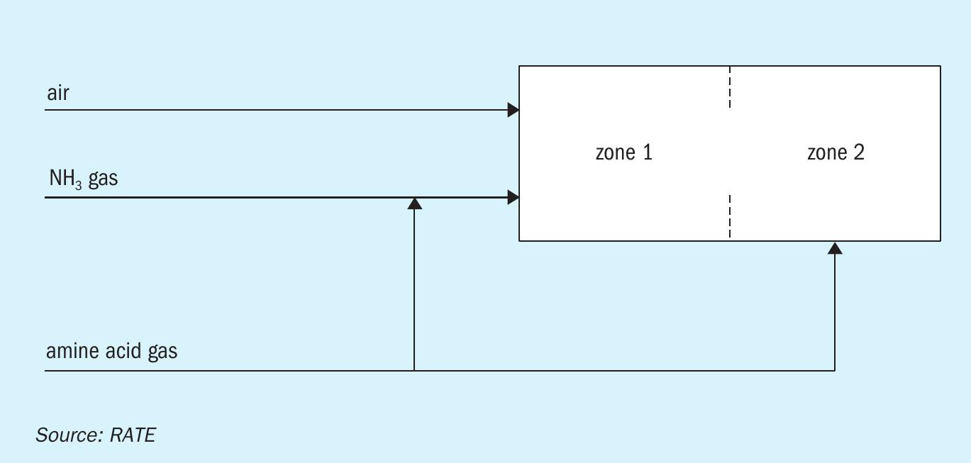
Processing the amine acid gas and the SWS Gas with the reaction furnace configuration would require a two-zone reaction furnace (Fig. 6). Based on extensive CFD modelling the best configuration for processing amine acid gas and the SWS gas was to have a two-zone reaction furnace. Some licensors use a single zone reaction furnace which lacks flexibility of operation. With a two-zone reaction furnace, if there is any fluctuation in the amine acid gas, the operator can adjust the flow rate of the amine acid gas to each zone to maintain the adequate combustion temperature, with one zone this isn’t an option.
In addition, using oxygen enrichment has the following requirements:
- new burner capable of ammonia burning with oxygen
- new SWS line with control system
- new oxygen line with control system
- new reaction furnace
- other equipment should be evaluated for any necessary modifications/ replacements
- all piping pressure drop should be checked for hydraulic limits
- refractory upgrade suitable for oxygen enrichment.
Conclusions
In a grassroots design, normal practice has been to process SWS in the SRU and to have separate sour water strippers for phenolic and non-phenolic water.
When it comes to the revamp and modification of existing SRUs the best option will depend on the specific situation and the purpose of the modifications.