Nitrogen+Syngas 376 Mar-Apr 2022

31 March 2022
State-of-the-art plant technology
PROJECT SHOWCASES
State-of-the-art plant technology
Saipem, Stamicarbon, Toyo Engineering Corporation and KBR showcase recent projects and latest technology for urea and nitric acid plants.
SAIPEM
Increasing the sustainability of urea plants with SuperCups
SuperCups was developed by Saipem, owner and licensor of the Snamprogetti™ Urea Technology, to boost the performances of urea reactors.This article analyses the technology from a theoretical viewpoint and discusses practical experiences based on the results of plants operating with SuperCups.
Urea formation is ruled by an equilibrium reaction and a limited yield of urea formation, with the consequence that some reagents will remain unconverted at the outlet of the synthesis section. These unreacted reagents require a continuous consumption of utilities (such as steam, cooling water and electric power) in the downstream sections to recover and recycle these unreacted reagents (dark-blue coloured streams in Fig. 1) back to the synthesis section.
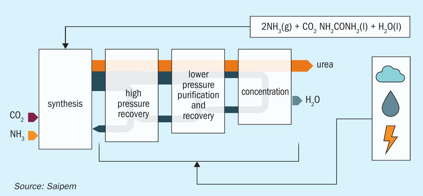
The quantity of utilities required for such recovery is directly dependent on the composition of the stream at the outlet of the reactor. It is therefore important to maximise the conversion in the reactor in order to decrease the energy consumption of the whole plant.
SuperCups have demonstrated their effectiveness for this purpose, proving to be, thanks to their triple fluid-dynamic effect, active reaction stages, rather than simple internals.
The first fluid-dynamic effect is the formation of a gas cushion below each tray; thanks to this cushion the gas (CO2 ) is evenly distributed along the reactor section providing a uniform feed to each cup. Second, the gas entering the cups is subject to intensive mixing with the liquid phase thus maximising the contact between the gas and the liquid phases. Third, is the improvement of the residence time distribution inside the reactor which allows the SuperCups design to be tailored to meet the specific demands of each plant.
SuperCups are applicable to both new reactors and to the retrofit of existing reactors.
By applying SuperCups to new reactors the investment costs (capex) associated with the reactors and the plot plan will be reduced, while installing the SuperCups in existing reactors will maximise their performance with consequent benefits to the operation costs (opex).
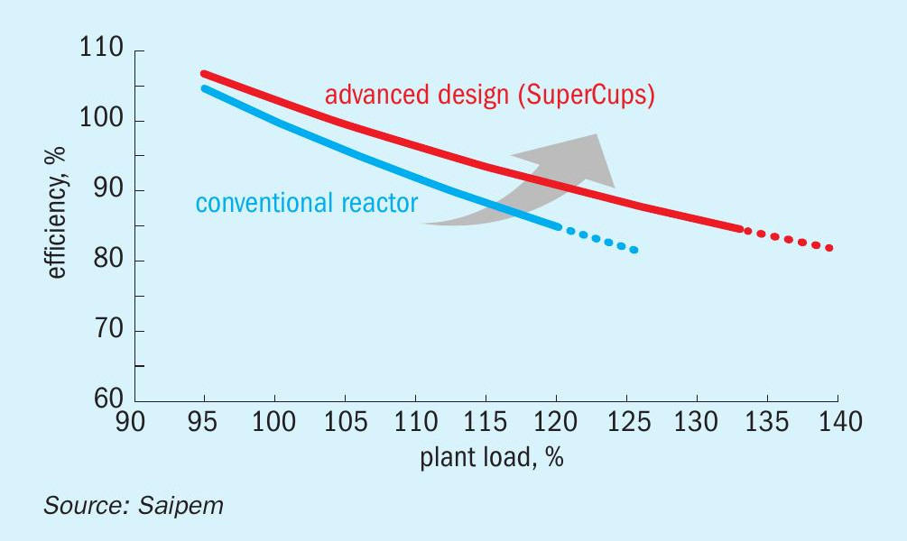
Fig. 2 plots the performance vs. plant load curves for a reactor with installed sieve trays and the same reactor after a retrofit with SuperCups. As can be seen, the Super-Cups have better performance, achieving a higher efficiency at higher plant loads.
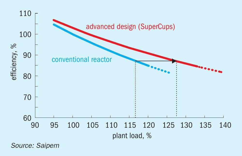
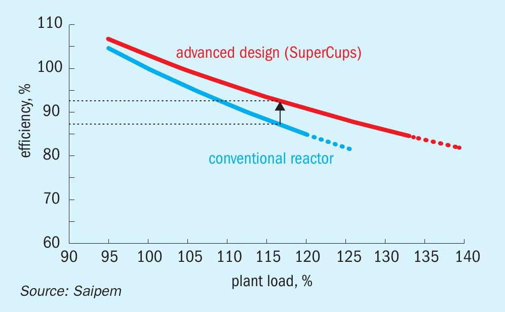
As shown in Figs 3 and 4 the installation of SuperCups can lead to two different operating approaches:
- operate at higher loads maintaining the same performances of the original reactor design;
- operate at same load increasing the performances of the reactor.
As can be easily inferred, these two approaches are not exclusive and can be combined to operate at any intermediate point in between the two (Fig. 5).
The number of SuperCups references to date since the first installation in 2014 is 25, each tailored to the targets of the plant.
The first applications of SuperCups were mainly installed to replace a limited number of trays (compared to the whole set inside a urea reactor).
For example, in one case a plant installed a total of seven SuperCups in the bottom of the reactor. Even with this “limited” intervention it resulted in a saving of 45 kg MP steam/t of urea together with a general increase of operability. These exceptional results have convinced the client to replace all of the remaining trays with new SuperCups trays. As of today (February 2022), the performance results are not yet available as the SuperCups are still in the manufacturing phase, but a further increase in operability is expected with total steam savings in the range of 70-90 kg/t of urea. 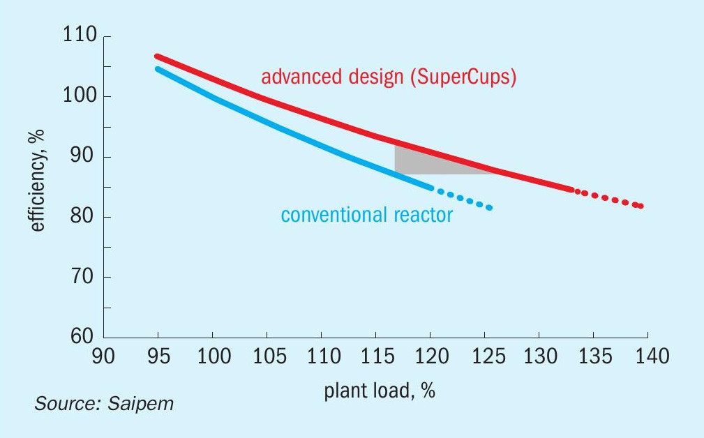
Such significant results appear to be reasonable when analysing the results obtained at another plant where a full set was installed; in this case the obtained steam saving, as demonstrated during the performance test, was more than 80 kg/t.
A similar case where SuperCups were installed in two phases is the Profertil plant in Argentina, where to begin with only four trays were installed in 2018 in the middle part of the reactor.
In this specific case, the number of SuperCups supplied in the first phase was determined by the need to replace some of the original sieve trays (significantly aged during the operation) and to adopt a fast track approach for the procurement (thus having to depend on the material available at the manufacturer’s workshop) to meet the turnaround schedule.
The analysis of plant data performed after the installation of the four SuperCups showed a steam saving of 15-20 kg/t of urea. In addition, this result was achieved with no variations to the pressure profile of the reactor which had the benefit of not causing any limitation nor increasing the power demand of the CO2 compressor.
The abovementioned results demonstrate that the capability of SuperCups to boost reactor performance is not limited to a specific portion of the reactor and does not require a minimum intervention making SuperCups suitable for all applications.
Enthusiastic about the obtained results, Profertil decided to complete the set of trays which was manufactured, delivered, and installed in 2021.
Plant data has demonstrated that the plant can be operated steadily at more than 120% and maximum achievable plant capacity has been increased by about 2-4%. The reduction in the consumption of MS steam to the urea stripper has been calculated to be about 90-95 kg/t of urea.
The benefits of SuperCups in terms of energy savings, operational flexibility as well as the possibility to optimise the size and layout of new urea units explains the fast growth of its applications worldwide in a very short time.
In terms of making urea production more sustainable, the reduction of medium-pressure steam consumption achieved in Profertil implies a net reduction of CO2 emissions to the atmosphere both associated to direct sources (e.g. due to combustion, flaring and venting) and indirect sources (e.g. associated to power generation, heating, cooling). The contribution in terms of carbon footprint reduction of urea production is estimated to be equivalent to the yearly greenhouse emissions of about 3,500 cars.
In total, as of February 2022 the sum of all SuperCups references is equivalent to almost 20,000 cars kept off the road for one year.
STAMICARBON
First operational experiences with Stamicarbon’s Ultra-Low Energy plant
The LAUNCH MELT™ Ultra-Low Energy design is Stamicarbon’s latest process technology, launched in 2012 and today contracted for six grass-roots plants. The first two plants to apply this technology were the Jinjiang Xinlianxin and Hubei Sanning plants in China with a capacity of 2,334 t/d each. They successfully went into operation in 2021. The Gemlik plant in Turkey and the Henan Xinlianxin plant in China are under construction, while two other plants for China are in the design phase.
Stamicarbon, the innovation and licensing company of Maire Tecnimont Group, considers this technology to be the next generation of its Pool Condenser and Pool Reactor designs, as it utilises major proven proprietary technological developments and benefits from considerably lower steam consumption.
N=3 heat integration
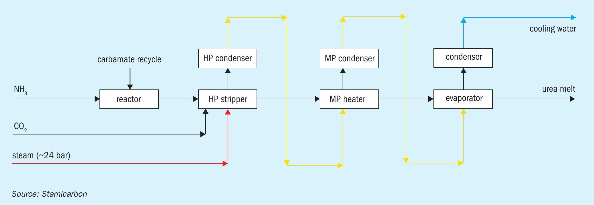
The traditional urea processes are based on a so-called N=2 heat integration concept, in which the heat supplied to the urea plant in the form of extraction steam from the steam turbine is used twice. Stamicarbon’s Ultra-Low Energy design is a breakthrough process technology that allows for heat supplied in the form of high pressure (typically 20 to 25 bar) steam to be used three times instead of two (Fig. 1). As a result, the steam consumption can be reduced by up to 40% and cooling water consumption by about 16%, compared to traditional CO2 stripping processes.
The first time this steam is used as a heating agent to obtain high stripping efficiencies in the high-pressure stripper. Subsequently, the heat is recovered by condensing the strip gas in the high-pressure carbamate condenser, pool condenser or pool reactor in the synthesis section to produce low-pressure steam that is used in the sections downstream of the synthesis section.
Process description
The Ultra-Low Energy technology retains all the features of the Pool Condenser and Pool Reactor designs, such as reliability, operability, and use of proprietary Safurex® stainless steels. At the same time, it uses less energy for urea production, lowering operating expenses (opex) substantially by significantly reducing steam consumption.
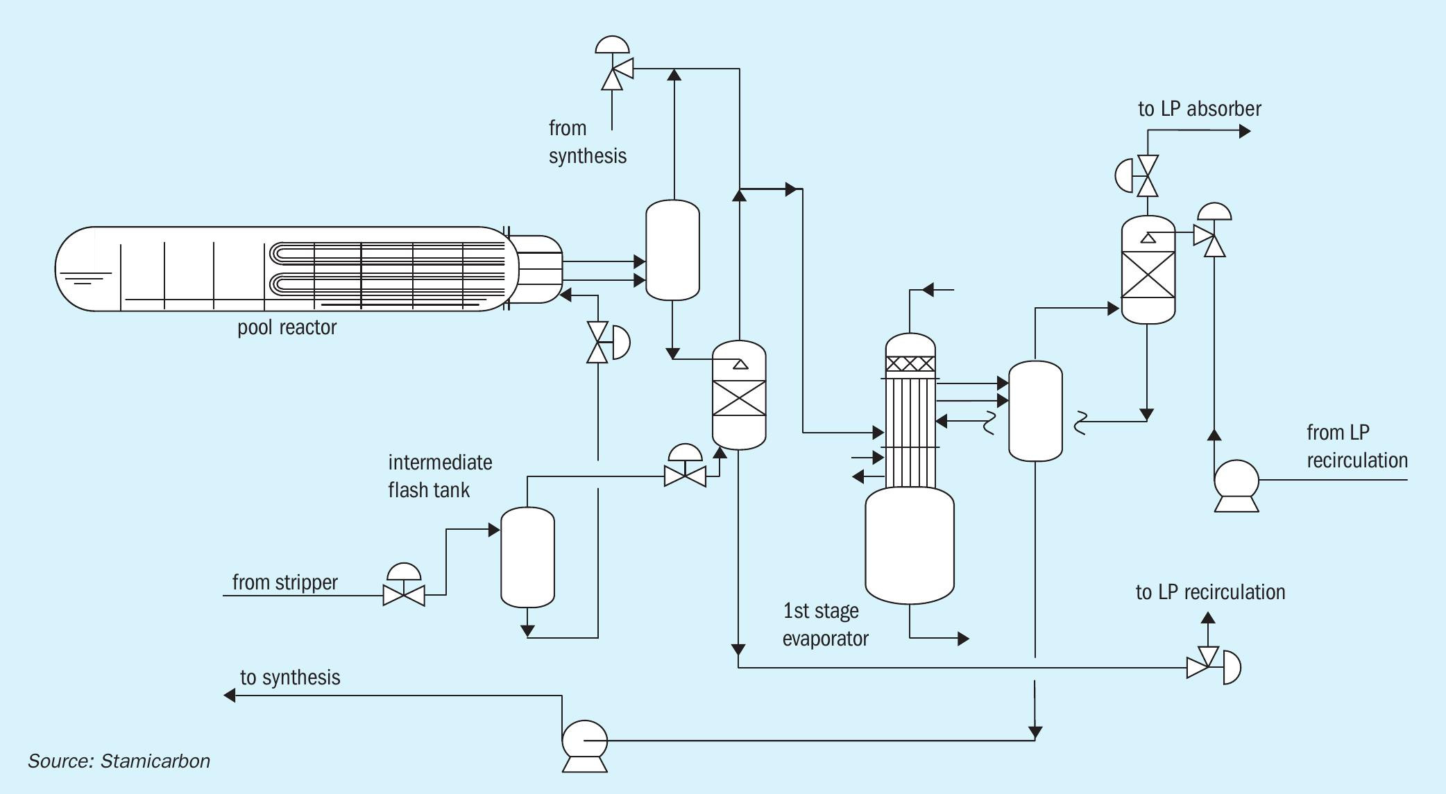
It differs from the other designs in the centrepiece of this technology, the Ultra-Low Energy pool reactor. This reactor has two U-tube bundles with two separate sections and handles two different fluid mediums. One bundle (‘steam bundle’) is for generating low-pressure steam and the second bundle (‘carbamate bundle’) is used for heat integration with the medium-pressure recirculation section.
On the shell side of the carbamate bundle, condensation of strip gas releases heat (at about 144 bara and 175°C), which is used to decompose carbamate into ammonia and carbon dioxide on the tube side. Consequently, the tube side of this tube bundle in the pool reactor functions as a medium pressure rectifying heater. By integration of these two functions, without any intermediate heat transfer medium, the available temperature difference between both process sides allows the bundle to be relatively small.
As illustrated in Fig. 2, the synthesis of the technology includes only two high-pressure pieces of equipment: a high-pressure stripper and a high-pressure pool reactor. The high-pressure scrubber is not required in the Ultra-Low Energy design thus optimising the capex of the plant.
In the Pool Reactor design, the total height of the high-pressure equipment structure is limited to about 20 m, where the heaviest piece of equipment, the pool reactor, is located. The stripper is located close to ground level. As the high-pressure scrubber is not part of the design, this results in the lower height of the structure. The vessel at the highest elevation in the plant is the first medium-pressure separator.
First start-up experience
The Ultra-Low Energy plant with prilled product of Jinjiang Xinlianxin with a capacity of 2,334 t/d was the very first plant with this innovative technology. It was successfully started up in February 2021. Prior to startup, the plant staff were thoroughly trained by Stamicarbon on its Operator Training Simulator to get a good understanding of the expected reactor and plant behaviour.The start-up of the plant went very smoothly without any issues from the very first attempt. Initially, the plant was operated with turndown capacity operation. After the feedstocks were assured, the capacity of the plant was increased to above 100% within the first week of operation.
The energy consumption of the Ultra-Low Energy plant is considered to be a benchmark performance worldwide. The presence of the medium-pressure recirculation section with the carbamate bundle dampens disturbances that occur in traditional CO2 stripping plants, originating from discharging liquid directly from the stripper operation to the low-pressure section.
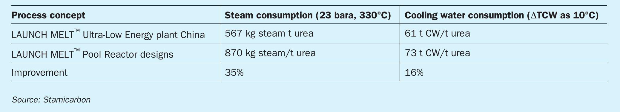
The actual plant operation information from Jinjiang Xinlianxin is indicated in Table 1.
The performance parameters at an average plant operation capacity of 102% demonstrate that the Ultra-Low Energy concept is a major advancement in urea technology. The actual high-pressure steam (23 bara, 330°C) consumption is 567 kg/t urea, which is even lower than the initially expected value during design. This is expected to be further reduced by about 20 to 25 kg/ton urea, by optimisation of the process conditions of the ammonia feed temperature to the synthesis. The steam consumption is reduced by about 35% and cooling water consumption is reduced by about 16% compared to the traditional Pool Condenser and Pool Reactor Designs. The capex of the Ultra-Low Energy design is comparable.
The successful commissioning and stable operation of the plant also validated the mechanical design of the Ultra-Low Energy pool reactor. The design fully employs the superior resistant properties of Safurex® Infinity∞ steel against corrosion. The tube bundles and the internals of the distribution box are accessible through the manway by opening the internal covers and thus enabling non-destructive testing inspection without restrictions and without dismantling of heavy parts.
The ease of operation is considered to be another important benefit of the Ultra-Low Energy technology compared to a traditional plant. This convinced the same customer to contract a second Ultra-Low Energy plant, which is currently under construction.
The technology can be used in grassroots urea plants, but can also be applied for revamping plants, irrespective of the original technology or capacity. It can replace the existing aging reactor to increase plant capacity, while simultaneously reducing energy consumption.
TOYO ENGINEERING CORPORATION
Engineering for sustainable growth
Carbon neutral policies are being vigorously pursued around the world and present a big challenge for engineering companies, but can also create many business opportunities. In particular, Toyo Engineering Corporation (TOYO) is a technology leader in areas such as carbon-free ammonia fuel, and sustainable aviation fuel (SAF) using biomass and carbon dioxide as raw materials. In emerging countries, on the other hand, resolving food issues and economic disparities remain a common challenge according to the United Nations. Demand for chemical fertilizers, petrochemical products, and a stable electricity supply is expected to continue to grow along with population growth and economic development in the world. TOYO, whose mission is “Engineering for Sustainable Growth of the Global Community”, recognises the importance of achieving a balance between harmony with the environment and economy and convenience. In this article, TOYO discusses three nitrogen and/or syngas projects corresponding to its mission.
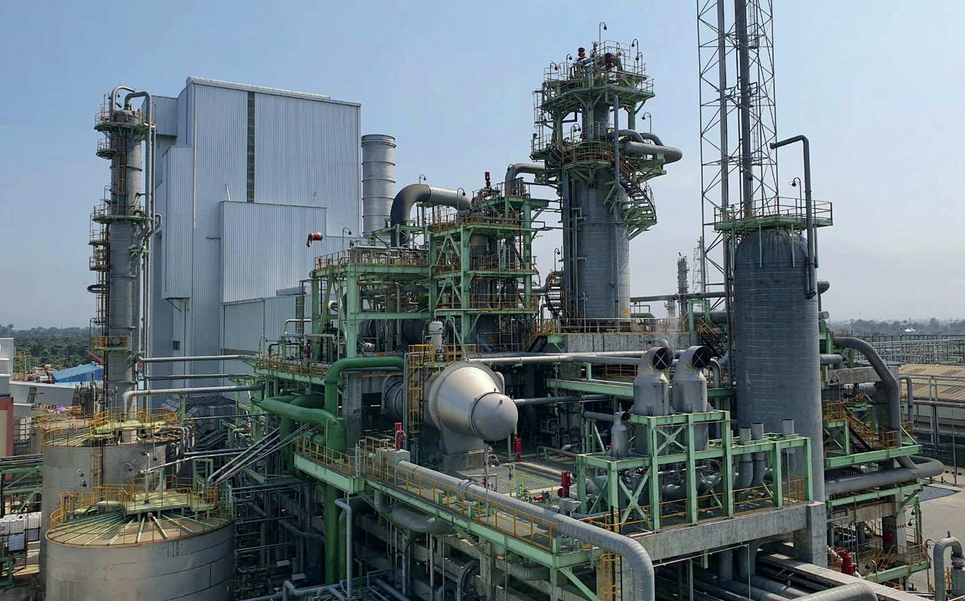
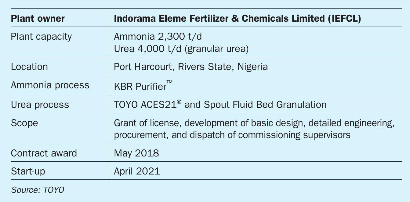
Indorama Train-2 project, Nigeria
In 2018, in the wake of the successful completion of the Train-1 project, Indorama Eleme Fertilizer & Chemicals Limited (IEFCL) awarded a contract to TOYO to build one of the world’s largest ammonia-urea complexes (Fig. 1 photo). The Train-2 project, located at Port Harcourt in Nigeria, has a design capacity of 2,300 t/d for ammonia (KBR Purifier™ process) and 4,000 t/d for granulated urea (TOYO ACES21® and Spout Fluid Bed Granulation). All milestones, including construction and the commissioning activities, were successfully completed in 2021. Especially for the initial start-up, the following events are regarded as being particularly noteworthy:
The KBR ammonia plant achieved the fastest record of 11 days from natural gas feed in to producing the first drop of ammonia.
The TOYO urea plant produced the first urea granules on the same day as the initial feed in of raw material from the ammonia plant.
Subsequently, the provisional acceptance of Train-2 was attained within two months of natural gas feed in and now the plant is being managed steadily by the owner at full load. The use of feedback from past projects, including Train-1, and the effective implementation of a start-up plan worked out with IEFCL helped the plant to start smoothly.
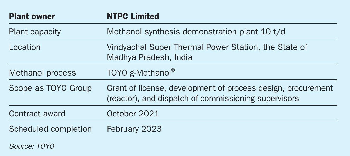
NTPC CO2 -to-methanol demonstration project, India
After competitive bidding, Toyo Engineering India Private Limited (TOYO-India), one of TOYO’s affiliates, located in Mumbai, India, has been awarded a contract by NTPC Limited for a 10 t/d methanol synthesis demonstration plant. This demonstration plant will be built at NTPC’s Vindyachal Super Thermal Power Station located in the State of Madhya Pradesh, India.
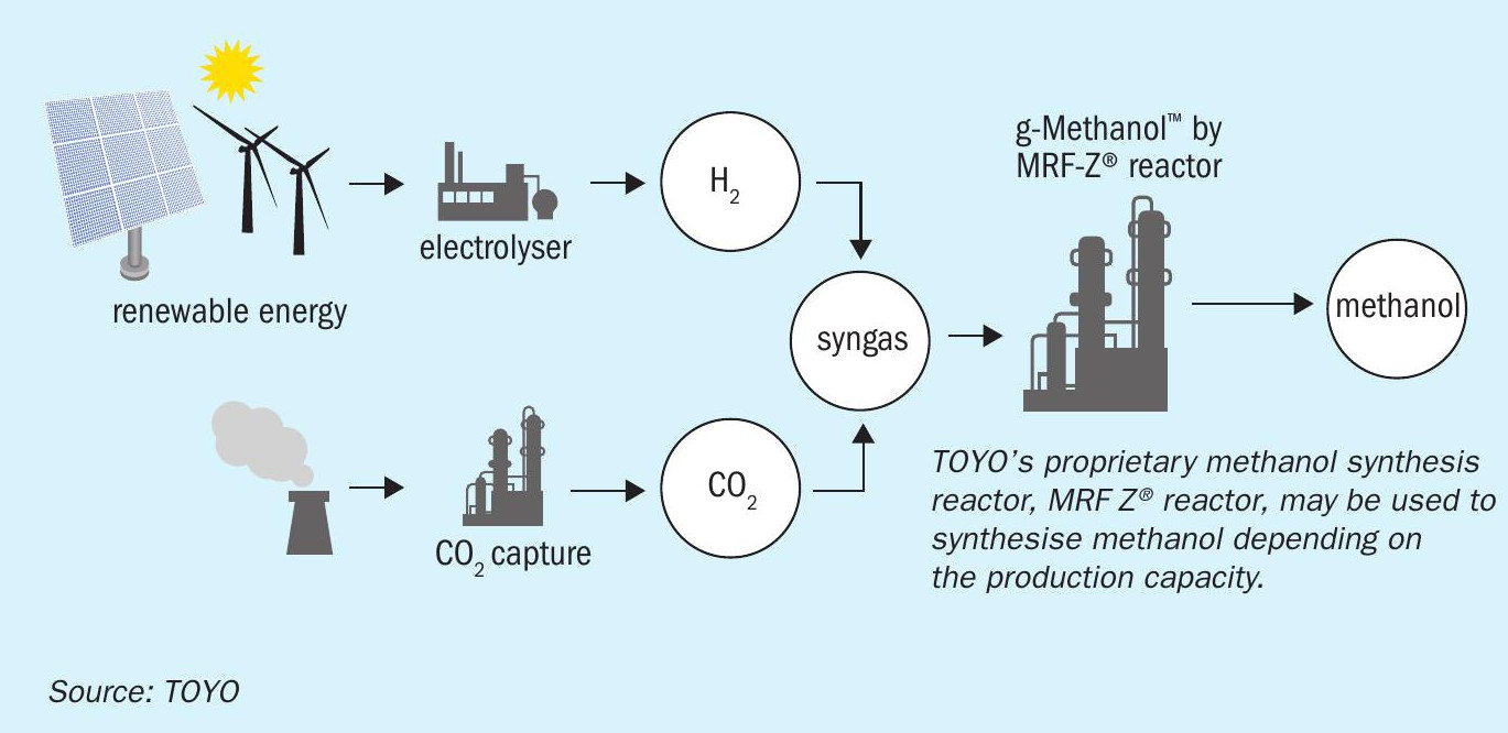
In this project, CO2 captured from flue gas and hydrogen generated by water electrolysis will be utilised to synthesise methanol. TOYO will provide its proprietary methanol synthesis technology (g-Methanol® ) for this project as a technology owner (see Fig. 2).
This project is part of NTPC’s initiative in the field of clean energy and an important step towards India’s commitment to addressing climate change. NTPC Ltd is a Maharatna company and India’s largest energy conglomerate with roots planted way back in 1975 to accelerate power development in India. The total installed capacity of NTPC as of date is 67+ GW (including joint ventures).
With the award of this project, TOYO group is pleased to contribute to the national goal of carbon footprint reduction.
Blue ammonia feasibility study
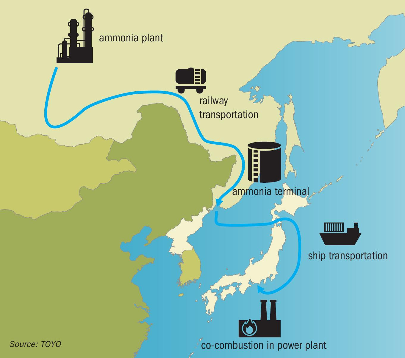
(This article was prepared in the middle of February). Following the implementation of Phase 1 of a study in 2020 for the establishment of a blue ammonia value chain between Eastern Siberia and Japan, in July 2021, TOYO and Irkutsk Oil Company (IOC), Japan Oil, Gas and Metals National Corporation (JOGMEC), and ITOCHU Corporation (ITOCHU) agreed to implement a detailed study for commercialisation as Phase 2. As with Phase 1, TOYO and ITOCHU have implemented Phase 2 study entrusted by JOGMEC and established a master plan for the value chain that converts natural gas produced by the IOC in Eastern Siberia into ammonia and transports it to Japan.
In Phase 2, for the commercialisation of a large-scale blue ammonia value chain from Eastern Siberia to Japan, TOYO has executed a conceptual design to produce ammonia from natural gas produced in IOC’s oil fields in Eastern Siberia. In this conceptual design, it is expected that CO2 emitted during the production of ammonia is utilised for CO2 EOR to increase oil production in the oil and gas fields in Eastern Siberia owned by IOC or other CCUS methods. For the inland transportation of ammonia, the utilisation of railway cargo or a pipeline is foreseen.
TOYO, IOC, JOGMEC and ITOCHU will establish a blue ammonia value chain between Eastern Siberia and Japan working in close collaboration to utilise the technologies and knowledge possessed by the parties (Fig. 3). The collaboration aims to contribute to the realisation of a sustainable society through efforts to reduce greenhouse gases by introducing blue ammonia in Japan and Asia as a fuel for thermal power plants, ships, and other uses, in line with its decarbonisation promise. The study is currently in an evaluation stage with all parties preparing further steps for moving ahead.
As demonstrated in these project examples, TOYO is striving to achieve both an environmentally-friendly society and to enrich people’s lives by combining the strategies of sustainable technology and business development as well as advanced EPC operation, as part of its medium-term management plan for stepping towards the future.
KBR
Nitric acid plant revamps
The owners of aging nitric acid plants face various challenges including reduced efficiency, reliability issues, high maintenance cost, and inability to meet local environmental standards. KBR’s proprietary process simulation support offers competitive and innovative solutions based on vast theoretical process knowledge leveraged by experience of a licensed fleet of 76 plants globally.
Recently and in the past KBR has identified typical challenges and resolved them through revamping, ensuring improved plant reliability and annual production by eliminating constraints, related to compressors, heat train and process bottlenecks.
The technologies from KBR offer superior capex, opex, and better energy efficiency with very low technical risk. The technology revamp solutions offered by KBR are further enhanced by proprietary equipment supply by KBR which meet best design, fabrication, and industry quality control standards. Thus, KBR can support clients with a complete solution from design to delivery.
Why revamps are important
Usually for any plant like everything else there is an expected life, and if an old plant is approaching the end of its lifetime, a major overhaul may be the best path forward. Not only this, but if the operator needs to improve plant output, reliability, or to adopt to changing business or environmental needs, a revamp can provide the solution to these needs.
Once overhauled, a revamped plant could run successfully for another 15 years or more. The revamping or re-structuring of existing plants is a preferred economic solution for almost every branch of today’s industries. It can become the perfect solution to re-establish competitiveness and comply with regulations and market demands.
Changes to the plant and its equipment are very likely to improve performance and reliability. Plant revamping to achieve capacity increase and modernisation to conform to ever changing regulations or product diversification can put an established production site back on top of the competition.
The following sections refer to KBR’s latest experience from recent successfully completed nitric acid projects across the globe and discuss the following revamp goals:
- process optimisation and capacity enhancement solutions;
- increase heat recovery efficiency;
- improve product quality – acid concentration increase;
- reduce N2 O and NOx emissions through NSCR & SCR to meet environmental regulations.
Process optimisation and capacity enhancement solutions
Optimisation is defined as “making the best out of a situation” and process optimisation is no different, it is an exercise that aims to streamline operations within a process, maximising resource use and improving overall output.
KBR is currently involved in and has completed various projects where the client wanted a capacity increase of 15-25%. Based on the experience from these projects the major areas to investigate to provide a successful revamp are summarised below.
Pressure profile
Once the design basis is defined, the first and one of the most important steps is a realistic pressure profile of the existing plant and a best evaluated pressure profile for the revamp. A capacity enhancement revamp requires more flow passing through the plant which in turn will result in higher pressure losses. This eventually can turn into lower power extraction from the expander and many more complications. The pressure of the entire train, therefore, needs to be increased to minimise pressure losses, while at the same time accommodating increased mass flow of gases in the existing plant equipment and maintaining optimum volumetric flow rates.
KBR’s inhouse software Poseidon is an important tool with high accuracy for estimating a very realistic pressure profile, which can be used to find a hydraulically and economically optimised solution.
Air compression
Air and ammonia are the two raw materials for producing nitric acid. The air availability from an existing air compressor often becomes a major bottleneck of the plant.
In case of revamping for capacity enhancement, the pressure of the plant has to be elevated as explained in the pressure profile section. KBR’s inhouse software Heat Train Run is used to provide the best results for process optimisation for such a unit balancing the elevation in pressure, heat balance and the power extraction from the expander etc.
Heat train
The heat train includes several exchangers connected in series that helps in recovering the heat generated by the oxidation reactions of ammonia into NO and further the NO into NO2.
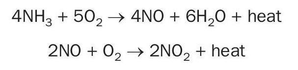
During capacity enhancement, the adequacy of these exchangers needs to be checked with the higher flows, heat flux, tube wall temperatures and differential pressures across the exchangers.
With capacity increase the temperature profile across the heat train can change significantly and may result in conditions that fall outside of the design conditions of the existing equipment. For these capacity increase cases KBR’s inhouse simulation software Heat Train Run is used to do the analysis. Based on close inspection of the results, outcome recommendations are made for any modification to the equipment or for the addition of any exchanger to further improve heat recovery, keeping in mind the techno economic feasibility of that option.
Absorber
The absorber is the heart of the nitric acid process where both the NOx oxidation and reaction of NOx with water take place simultaneously to produce nitric acid. As explained above, during a revamp the pressure of the entire train is increased to minimise the pressure losses and to accommodate an increased volume flow of gases in the existing equipment.
This will result in the absorber being operated at a higher pressure than the existing operating pressure and it will partly help in reducing the NOx emissions from the absorber.
A higher pressure in the absorber increases the partial pressure of O2 , which promotes oxidation of NO to NO2 . This results in an increase in absorption efficiency in the absorber.
In cases where simulation indicates that the NOx emissions are still too high even at a higher operating pressure, the option of using chilled coils in the absorber can be explored. In two recent projects in India the option of chilled water coils in the absorber worked well.
The lower temperature of these chilled water coils makes the rising NOx vapours easier to condense and will greatly help in achieving controlled emissions from the absorber.
KBR has recently provided an absorber to a client in the US. The existing absorber has reached the end of its life and is a limiting factor for capacity increase. KBR has therefore designed an absorber that is sized for the future capacity expansion in consideration.
Excess tail gas
While increasing the capacity of the plant, the amount of tail gas coming from the absorber also increases as the total air flow increases. The expander intake volume becomes a bottleneck as it operates on a fixed volumetric flow basis.
Hence the excess tail gas needs to be bypassed around the expander. The option of heat recovery in this tail gas bypass can be explored.
Increase heat recovery efficiency
Efficient heat recovery is important in minimising the operational costs of plant like the energy required for driving the air compressor in this case.
The KBR proprietary design helps to efficiently recover the heat from the process gas as the reaction moves in the forward direction, either by generating steam or by heating the tail gas coming from the absorber. The energy is recovered and used to run the steam turbine or expander respectively.
While increasing the capacity of plant, the power required by the air compressor to deliver more air will increase and mostly, this power will be generated through the gas expander through which the heated tail gas is passed, and energy is recovered. Since the expander can only handle a fixed volumetric flow at a defined inlet pressure, the rest of the tail gas (approximately 25%) will bypass the expander and steam is generated through the tail gas bypass which can be exported or used in any of the steam heated exchangers based on the plant configuration.
Recently, in revamping a KBR designed plant in the US to enhance heat recovery, an oxidation spool piece and low-pressure waste heat boiler were added downstream of the tail gas heater which helped in increasing the oxidation volume, improving the conversion of NO to NO2 , while also increasing recovering heat and generating steam.
Improve product quality – acid concentration increase
Product quality is more critical for plant owners wishing to sell their product in the market. The quality of the product acid is measured by the dissolved NOx content in the product acid. Over time, as the plant reaches the end of its lifetime, the quality of the product may start to deteriorate. As a process licensor, KBR understands the importance of product quality and can offer a proprietary absorber and bleacher column designed by KBR to maintain or improve the quality of the product acid.
KBR solutions recommended to clients include the installation of a new bleacher column or the addition of a new bleacher column in series with the existing one to mitigate acid quality problems.
As part of a revamp, clients may also need to increase the concentration of the product acid according to market requirements and, in most cases, KBR has offered the solution by adjusting the absorber feed water requirement or by changing the product acid tray. In the past KBR has also used a pre-absorber to increase acid concentration.
Reduce N2 O and NOx emissions to meet environmental regulations
N2OAbatement
Nitrous oxide (N2 O) is a powerful greenhouse gas with a global warming potential of 298 CO2 equivalents. N2 O molecules remain in the atmosphere for an average of 114 years unless removed by a sink or destroyed through chemical reactions.
As of 2019, nitrous oxide accounted for nearly 7% of all greenhouse gas emissions resulting from activities like agriculture, fuel combustion, wastewater management, and industrial processes in the US.
In recent revamp projects KBR’s tertiary N2 O abatement system has been helping nitric acid producers worldwide to meet governmental environment regulations and to keep the planet clean and green.
In the KBR tertiary control system, N2 O is catalytically decomposed into N2 and O2 as follows:
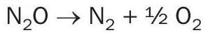
The process uses a proprietary Fe/Zeolite based catalyst. This catalyst can be bought in pellet form or as monolith bricks. The tertiary N2 O abatement can remove up to 98% of the N2 O content in the tail gas stream.
NOx abatement
The tail gas, which has been reduced in NOx content, leaves the absorber, and flows to the tail gas reheating system. New emission norms across the world have become stringent with respect to NOx emissions. As a solution KBR provides a NOx abatement system for all of its new plants.
Capacity increase/plant deterioration/ availability of utilities can all increase the NOx content from the absorber. In recent projects to increase capacity KBR has made sure that the NOx content remains within the norms in the tail gas before being vented into the atmosphere.
NOx can be controlled to a limit by modification of the heat train and absorber. A NOx abatement system should be installed, or the capability of the existing NOx abatement system should be checked.
Tail gas exit from the hot gas expander is mixed with a small stream of ammonia vapour and is recycled in the ammonia/tail gas mixer before entering the NOx abator.
In the NOx abator, the tail gas NOx concentration is reduced to less than 25-50 ppm by volume. A start-up heater located upstream of the NOx abator is used to heat the tail gas before gauze light-off. The startup heater utilises steam to heat the tail gas to approximately 205°C. This ensures that the NOx abator can operate during start-up and controlled shutdown to help achieve a near colourless tail gas stack.
In recent times KBR has offered the most advanced retrofit NOx and N2 O abatement systems for existing nitric acid units, upstream or downstream of expander gas heater (low temperature or high temperature applications based on client preference and the existing plant configuration).