Sulphur 402 Sept-Oct 2022
30 September 2022
War stories revisited
SRU TROUBLESHOOTING
War stories revisited
Marco van Son and Frank Bela of Comprimo share lessons learned from SRU war stories, including: inadvertent NH3 destruction in an oxidising atmosphere, rich amine emulsion, SWS fixed valve trays, H2 spiking of SRU feed, rich amine flash drum early warning, V-ball fuel gas safety shutoff valves, TGTU methyl mercaptan, and commissioning and Murphy’s Law.
Inadvertent NH3 destruction in an oxidising atmosphere
This incident is best prefaced by a brief overview of the history of ammonia destruction in the SRU thermal reactor. In the 1950-60s it was generally assumed that complete NH3 destruction required excess air (“oxidising atmosphere”). This typically resulted in a two-zone thermal reactor, where all sour water acid gas (SWAG) and combustion air was routed to zone 1, and at least some amine acid gas (AAG) bypassed to zone 2.
Processing SWAG in this manner typically resulted in downstream formation of sulphuric acid (H2SO4 ) which (1) deactivated alumina by forming aluminium sulphates, (2) deposited solid ammonium sulphate [(NH4)2SO4] and bisulphate (NH4HSO4) if NH3 was present, and (3) corroded steel upon condensation in the condensers. The fundamental mechanism appears to be initial formation of byproduct NO2 which subsequently oxidises SO2 to SO3 (thus forming sulphuric acid vapour) in the waste heat boiler, where the reaction is favoured at <500°C (932°F).
This was generally accepted as the price one had to pay until around 1970 when two developments revolutionised the industry:
- Comprimo demonstrated that efficient NH3 destruction could be achieved in a single-zone thermal reactor with proper temperature, residence time and mixing by virtue of a high intensity burner.
- The Ralph M. Parsons Company continued to favour the two-zone furnace concept while limiting the AAG bypass to ensure excess H2S in zone 1.
The industry remains split between the two camps. As usual, each has its pros and cons, summarised to a cursory extent in Table 1.
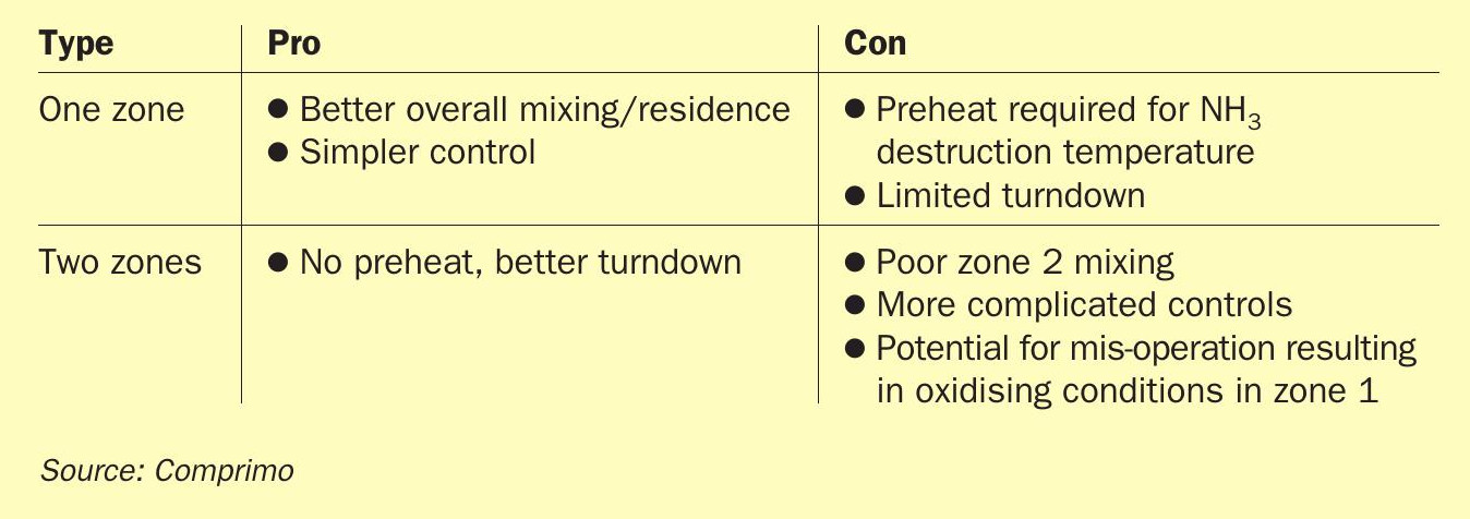
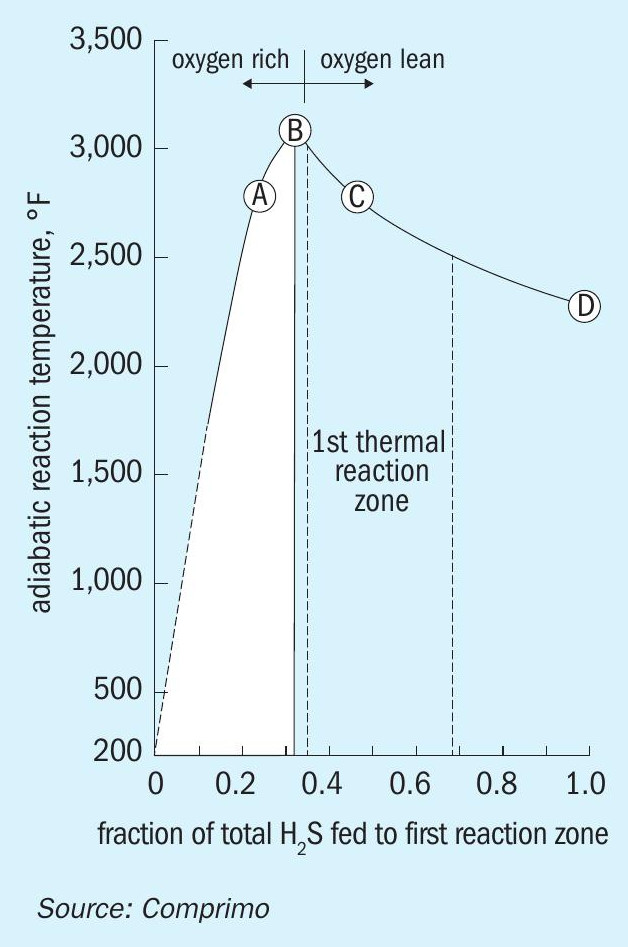
In the 2-zone case, the relative zone 1 temperature is determined by the AAG split. Since the Claus process only oxidises one third of the H2 S, routing one third to zone 1 maximises the temperature, where 1,300°C (2,372°F) is considered ideal. Arguably more important, however, is maintenance of reducing conditions (excess H2S) in zone 1 to avoid downstream formation of H2SO4 (Fig. 1).
Actual H2S split will be approximate, given likely errors in flow measurement and assumed acid gas H2S concentrations. In addition, mixing efficiency – important to minimise localised NOx – is less than perfect. To ensure excess H2S, at least 40% of the total H2S should be routed to zone 1. However, maximising AAG to zone 1 is also desirable for better mixing and residence time, provided 1,250-1,300°C is maintained.
In the subject incident, a client operating a 2-zone thermal reactor called to report excessive dP several days after startup following a maintenance outage. SWAG was not being processed, but AAG was known to typically contain substantial NH3 due to inadequate purging of ARU reflux. Eventually it came to light that there also was no sulphur rundown from the first condenser because the Sultrap was plugged with corrosion scale; all sulphur made in the thermal reactor was carried over to the reheater. Cleaning the Sultrap restored normal sulphur rundown flow, but No. 1 reheater pressure drop remained high, accounting for 75% of total SRU DP (while bypassing TGTU).
The unit had been heated up by firing H2, and excess air was likely greater than intended based on evidence suggesting H2 flow was overstated. As AAG was introduced to zone 1, temperatures approached the 1,500°C trip point while still to the left of point B in Fig. 1, prompting the operator to route additional AAG to zone 2.
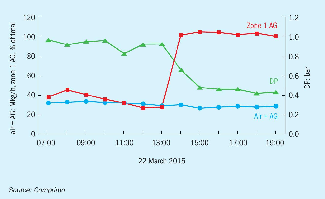
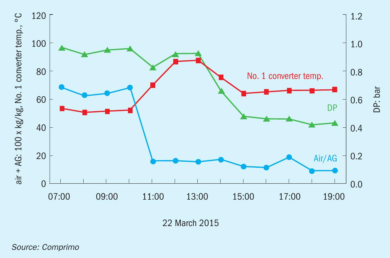
When Comprimo arrived on site a couple of days later, the situation was still unclear, so the first order of business was to restore a normal reducing atmosphere in zone 1. With some coaxing, the operator shifted substantial AAG to zone 1 quickly enough to transition from point A to C without passing through B. To everyone’s surprise, the unit pressure drop subsequently decreased by 50% over the next two hours (Fig. 2).
The explanation lies in the No. 1 converter exotherm (Fig. 3).
As an aside, prior to shifting the AAG split, the unit was found to be off-ratio and combustion air (blue) reduced accordingly (~20%), resulting in the increased No. 1 converter exotherm (red). However, Fig. 3 reveals that the reduced DP was not the result of reduced air flow, but of increased sulphur conversion in the thermal reactor when acid gas was shifted to zone 1 – presumably due to better mixing and longer residence – as evidenced by subsequent reduction in the No. 1 converter DT. Since fouling was confined to the reheater, reduction in process gas volume due to additional upstream sulphur condensation was apparently sufficient to significantly reduce system ∆P.
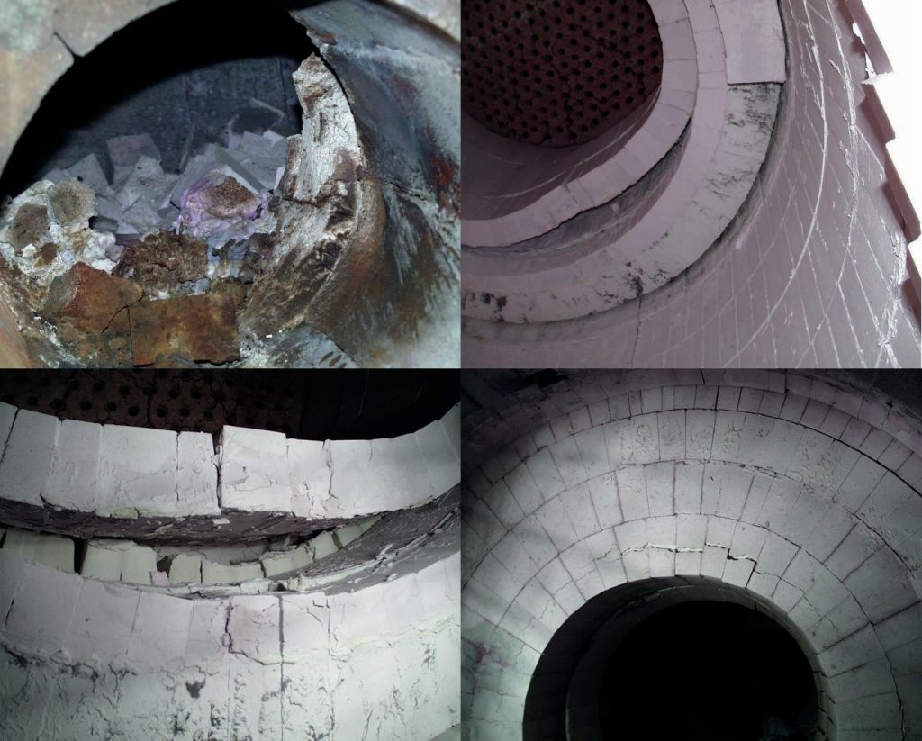
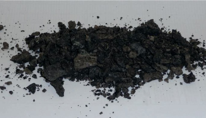
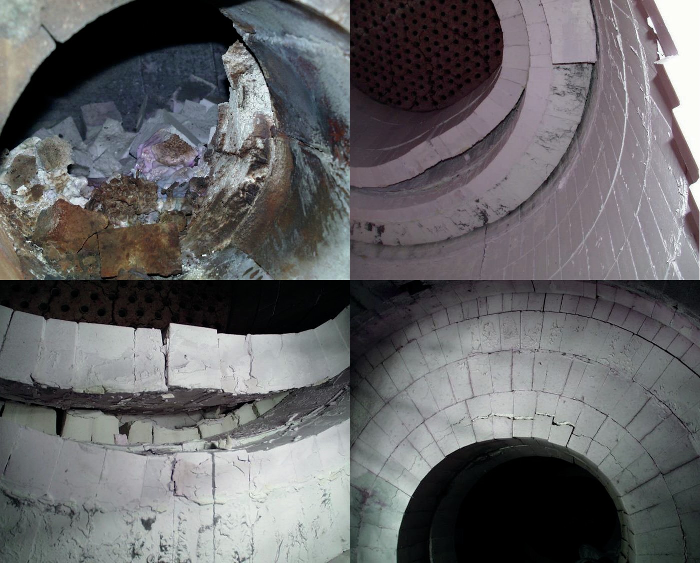
Following shutdown, the process (shell) side of the reheater U-tube bundle was found to be packed predominantly with iron sulphate, suggesting that most of the sulphur had been vaporised. The deposits were porous, easily crumbled and highly soluble in water yielding a strongly acidic pH (Fig. 4).
By comparison, clinkers of corrosion products found in the Sultraps were harder with more of an iron-slag appearance.
Rich amine emulsion
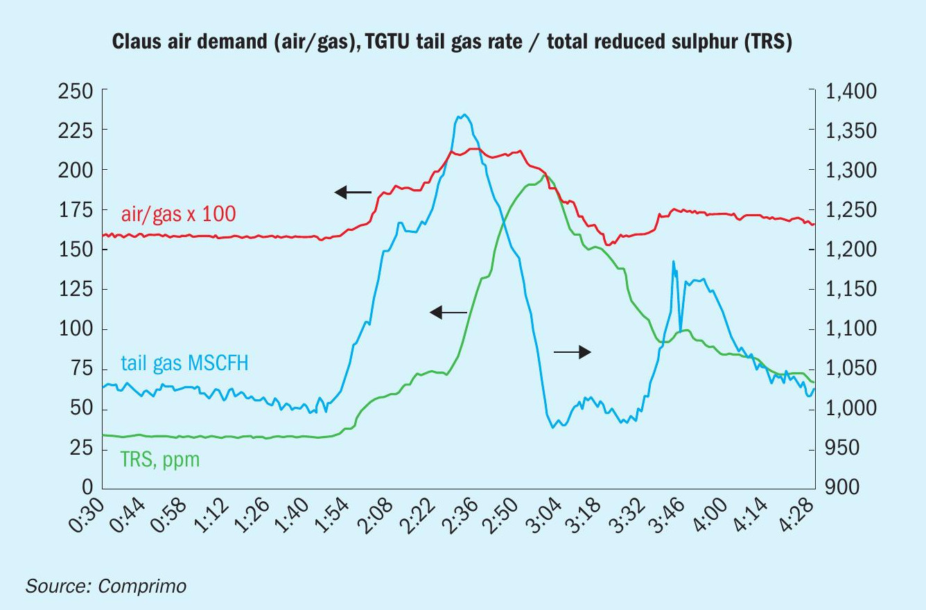
A refinery began experiencing apparently random episodes of increased SRU air demand due to hydrocarbons (HCs) in the amine acid gas. Fig. 5 is a relatively severe example. Amine acid gas (no SWAG) air demand increased 30%, TGTU absorber off gas increased 35% and total reduced sulphur (excluding H2 S) in the TGTU tail gas went from 25 to 190 ppmv.
High raw produced fuel gas temperature (130°F/54°C) to the delayed coker DEA contactor was quickly identified as a likely cause, potentially compounded by the fact that upstream lean oil absorption had been discontinued because entrained oil was suspected of accelerating fouling of the amine contactor. Historically, little attention was paid to the relative lean amine temperature because foaming was seldom a problem. The rich amine routinely contained copious amounts of free naphtha/ oil, but 30-40 minutes of residence at 0 psig in the rich surge tanks appeared to achieve adequate separation.
Lowering the coker raw gas temperature appeared to reduce (but not eliminate) the episodes, which tended to coincide with coke drum blowdown to the flare gas recovery compressor. It eventually came to light that the operators – in a misguided attempt to reduce exchanger fouling – had been manually throttling the cooling water to the compressor interstage and after coolers, resulting in raw gas temperatures of ~200°F (~93°C) at the inlet to the vapour recovery absorber during blowdown.
It is logical to conclude that emulsions, like foaming, are not caused by all HCs, just surfactants. The conclusion was that proper cooling resulted in condensation of naphtha which absorbed problematic organics – aromatics, most likely – in particular abundance during early coker blowdown.
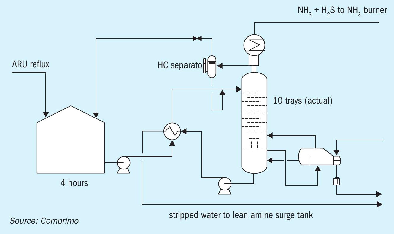
That the surfactants did not appear to cause regenerator foaming is perhaps attributable to the fact that the regenerators in this case were not refluxed – thus avoiding recycle build-up of contaminants within the column – but overhead condensate instead stripped in a separate amine-system SWS with four-hour feed residence (Fig. 6). However, emulsions were clearly evidenced by hazy “reflux.”
Lessons learned
- Coking units in particular are a likely source of surface-active organics conducive to stable amine emulsions (and foaming).
- Emulsified HCs can substantially increase SRU air demand without obvious signs of foaming or increased flash gas in the rich amine flash drum.
- While foaming concerns are typically cited as the reason for maintaining absorber amine temperatures above the HC dew point, potential emulsions are also a consideration.
- Trending SRU air/acid gas ratio is a useful means of promptly recognising HC excursions.
As an aside with regard to the last bullet, Comprimo often receives client requests to provide acid gas HC analysers – not for closed-loop feed-forward air demand control, just early warning of an impending upset. With reference to Fig. 5, Comprimo suggests that monitoring a continuous trend of air/ acid gas ratio is a simpler solution. The DCS operator eventually figures it out anyway when the trim air valve goes wide open, but with the trend it becomes obvious sooner.
Other hydrocarbon incidents
- Periodic surges in SRU air demand were ultimately traced to manual blowdown of LPG from a hydrocracker’s HP flash drum to the LP flash, where subsequent flashing was sufficiently violent to entrain liquid overhead to the amine contactor and ultimately the ARU. Resultant HCs in the amine acid gas were estimated at 15-25 wt-%. Fortunately, the SRU was generally at low rate and the surge only lasted a few minutes, thus allowing the plant to recover before TGTU recycle build-up became unmanageable.
- In a case of light naphtha entrainment from a hydrocracker, the HCs readily separated in the rich amine surge tanks at a rate that would fill the rich and lean tanks in about 20 minutes from the time that the operator happened to notice that the rich tank levels were steadily rising. The sulphur plant operations supervisor had reason to suspect the hydrocracker, but the operator insisted they were not the source.
- Unconvinced, the supervisor drove the two miles to the unit and drew a sample, which clearly had at least a 2% naphtha layer. Either the hydrocracker operator did not give the sample sufficient time to separate or did not consider 2% significant due to failure to appreciate the cumulative impact.
- Major light liquid HC carryover from a hydrocracker flash drum passed all the way through the ARU to the thermal reactor, due to malfunction of the acid gas KO drum high-level shutdown interlock. Flashing in the thermal reactor resulted in a pressure surge sufficient to collapse the overhead refractory before the SRU tripped on high pressure or flameout. The unit was down a month for repairs (Fig. 7).
SWS fixed valve trays
This case study dates back 20 years and has been previously published in various forms. It remains noteworthy because one seldom sees such a clear-cut real-world validation of a product’s superiority.
A refinery’s SWS charge was nominally 50% crude clearing water, and thus high in TDS/heavy organics despite substantial removal of solids, oil and grease in Wemco induced gas flotation units.
Closure of the ½-inch sieve tray holes was a chronic problem. Tray deposits were a combination of Ca/Mg carbonate/silicate and organics, which are largely insoluble in methylene chloride and therefore presumed to be high-MW polymerisation products.
Given the erosive nature of steam, it was difficult to comprehend the fundamental mechanism by which bridging of the holes occurred. One source rationalised it by explaining that vapour flow through an orifice creates venturi effects which draw liquid into the throat so as to form a laminar boundary layer at the edge of the hole, within which water tends to evaporate, salts crystallise, and organics polymerise.
This led to speculation that fixed valves might tend to avoid bridging of the holes by inhibiting the induction of liquid into the orifice throat. Whether or not that particular analysis is valid, other industry experts had also concluded that directional fixed valves were generally superior to both sieves and conventional valves in fouling service, specifically recommending Nutter MVG and Glitsch Minivalve trays.
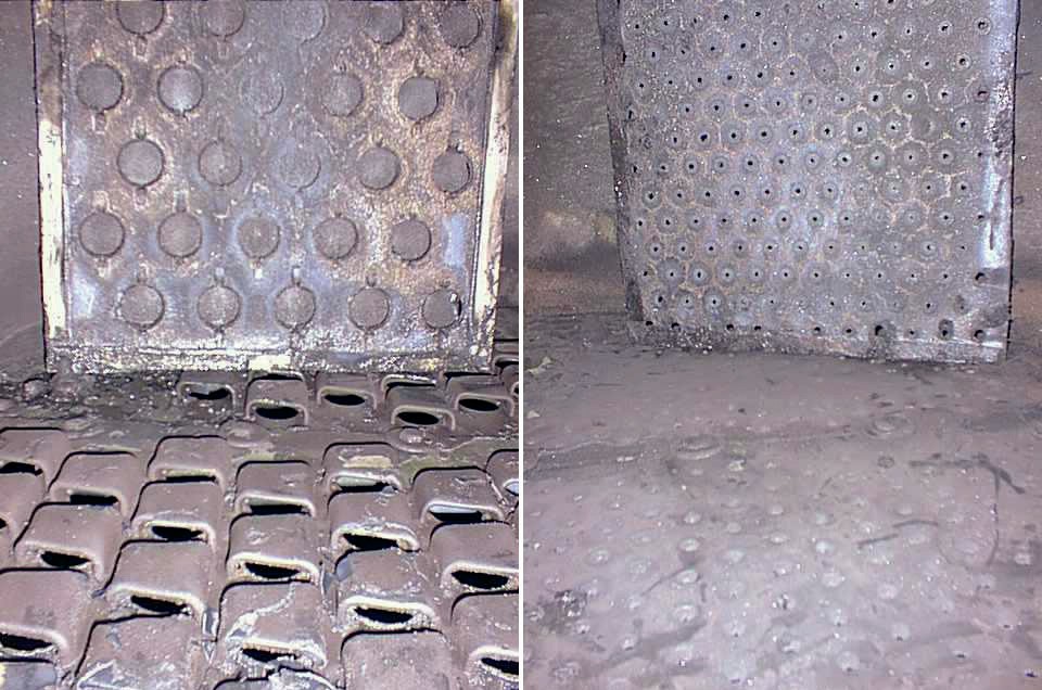
Norton (now Koch-Glitsch) Provalve trays were installed at two adjacent levels in the south stripper as a trial. The test trays were located 9-10 trays down from the top of the 40-tray stripping section, where fouling is typically the worst (presumably due to localised pH elevation). After a typical five-month run, adjacent sieve tray (½-inch holes Fig. 8 left photo) flow area was reduced by ~90%, while the test tray (nominal 1½-inch holes, right photo) flow area was only reduced by 10-15%. (Shown in the upper sections are the tray inspection manways, propped up to reveal the underside.)
On the success of that trial, the companion stripper was retrayed with Provalves. The vendor also claimed a 35% capacity increase (with no increase in active area) and a 20% reduction in pressure drop, which has essentially proven out. The Provalve tower, previously limited to 450-480 gpm, has since been operated at 600+ gpm, and tower DP was noticeably less than the (clean) sieve-tray tower at comparable rates (effectively increasing reboiler capacity). (Both towers are identical in design and charging the same feed.)
After 150 days, the Provalve tower could still process 550-600 gpm with no apparent increase in tower DP. After 130 days during the same period, the sieve-tray tower was flooding at 200 gpm and had to be shut down again for cleanout.
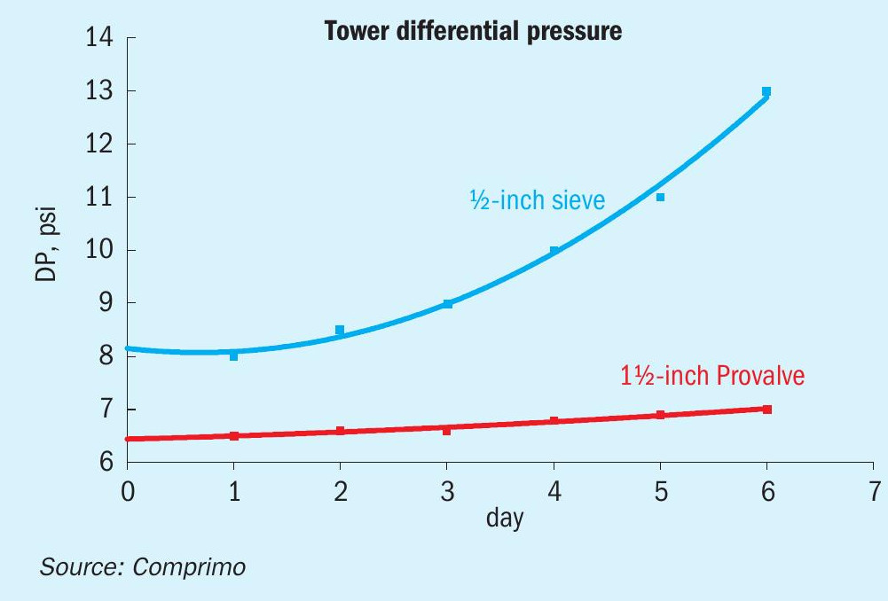
An accelerated fouling test was inadvertently conducted in early September 2002, when the sour water became contaminated with an inordinate amount of caustic, greatly increasing the fouling tendency over the next 2-3 weeks. During the period plotted in Fig. 9, both strippers were charging the same feed at a constant rate of 345 gpm each. As of Day 0, the sieve-tray tower had been online 42 days since the last cleanout, and the Provalve tower had been online 191 days. As of Day 8 the sieve-tray tower had been derated by 50%, and within another couple weeks had to be shut down again for cleanout.
The Provalve tower remained online after ~490 days, although it had been derated to 250-300 gpm (depending on H2S/NH3 loading), largely due to the caustic excursion.
H2 spiking of SRU feed
A 10-t/d SRU was forced to operate indefinitely at 10/1 turndown. Normal turndown issues were compounded by (1) chronically substantial hydrocarbons in the amine acid gas, (2) SW acid gas feed and (3) cold winters. The high turndown had the following key impacts:
- Thermal reactor temperatures were too low for destruction of NH3 and normal hydrocarbon levels, where the latter was evidenced by brown sulphur.
- The reheaters relied upon the SRU waste heat boiler for 600 psig steam, with surplus let down to the refinery 300 psig header. Reheater demand often exceeded supply, resulting in local header pressures as low as 300 psig and insufficient to maintain the converters above the dew point.
With regard to the latter, it was apparent that a lot of bare steel (valves, flanges, man-ways, nozzles, etc.) contributed to excessive heat loss – estimated at up to 85% – from the local 600 psig steam system. Improved insulation mitigated this considerably but did not address the greater problem of low furnace temperatures.
Since the thermal reactor was designed for front/side split of the amine acid gas for NH3 destruction, turndown issues were overcome for four years by co-firing natural gas in zone 1 while routing all amine acid gas to zone 2. This was effective, but had its shortcomings:
- NH3 gas continued to be flared due to perceived risk of generating soot, or NO2 conducive to downstream sulphuric acid formation.
- Hydrocarbon excursions often generated soot which, in addition to producing dark sulphur, fouled the catalyst beds.
A study concluded that H2 enrichment of the acid gas was the best option, with all feed to zone 1. Supplemental CRU H2 piped to the TGTU reactor was never used, since hydrocarbons in the acid gas consistently resulted in abundant tail gas H2. For three scenarios ranging from 0.5 to 2 t/d, heat and material balances were developed to determine (1) H2 required for sufficient supplemental heat and mass flow to overcome estimated heat losses, and (2) moderating steam required to limit thermal reactor temperatures to 2,550°F (~1,400°C).
Project success exceeded expectation in that equipment fouling and sulphur contamination due to acid gas hydrocarbons were significantly mitigated by H2 cofiring.
Rich amine flash drum early warning
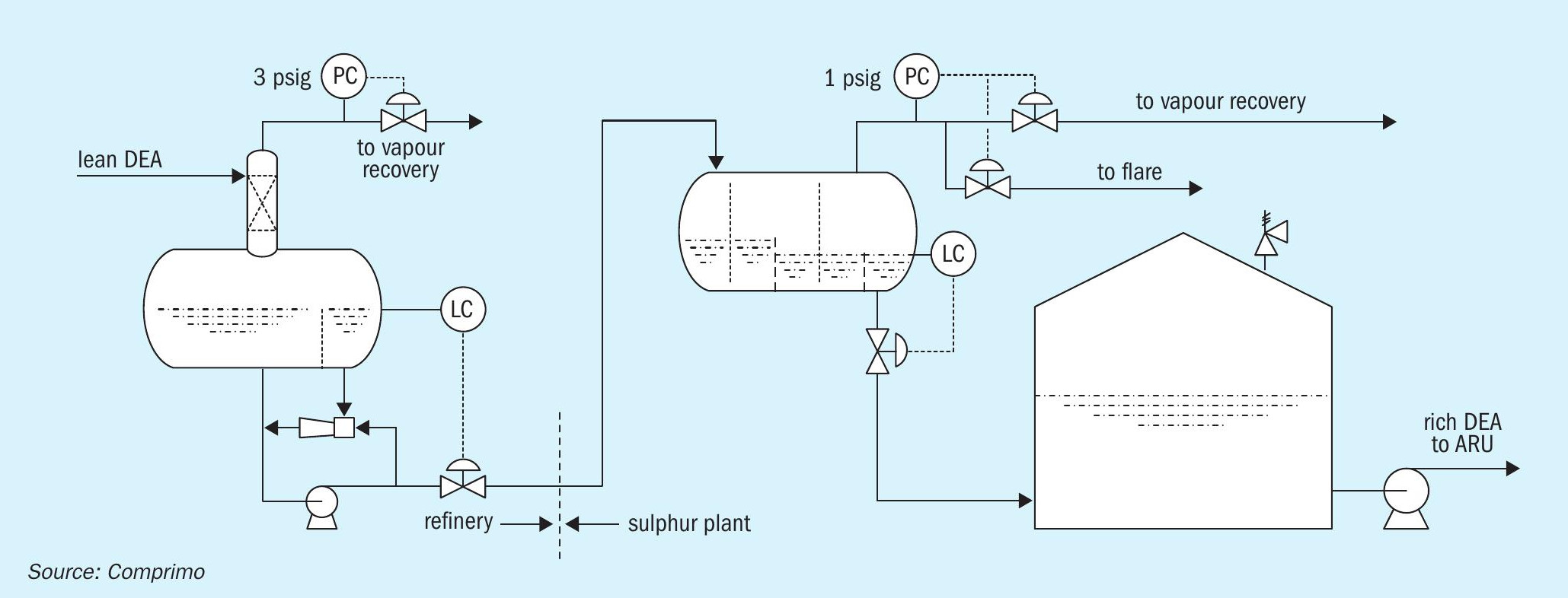
This refinery had a common DEA system circulating 1,500 gpm to six gas contactors and two LPG contactors. The rich amine flash drum operated at 2.5 psig with 10 minutes residence. The sulphur plant was two miles away, requiring 20 minutes for the amine to get there.
The hydrocracker was in the midst of start-up when (unbeknownst at the time) the depropaniser began carrying over LPG to the gas contactor due to a faulty reflux accumulator level signal. The refinery flash drum was overwhelmed with LPG, much of which carried through to the sulphur plant, causing the rich amine surge tanks to vent to atmosphere and thus resulting in a major environmental incident.
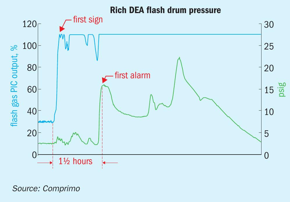
The flash drum off-gas rate was not measured. The off-gas regulator normally operated very consistently at ~30% open. LPG carryover was not evident to anyone at the refinery until the flash drum console operator got the high drum pressure alarm at 15 psig. However, the incident investigation revealed that the off-gas regulator had gone wide open > 1½ hours before the high-pressure alarm sounded (Fig. 10).
As a result of the incident, a high off-gas controller output alarm was added, and provisions made for the sulphur plant console operator to also monitor flash drum operation as well as receive key alarm signals.
Since the remote sulphur plant had adequate liquid HC separation, the refinery flash drum made no attempt to skim. However, it was also considered important not to accumulate HCs, which were therefore continuously re-entrained via a simple recycle eductor (Fig. 11).
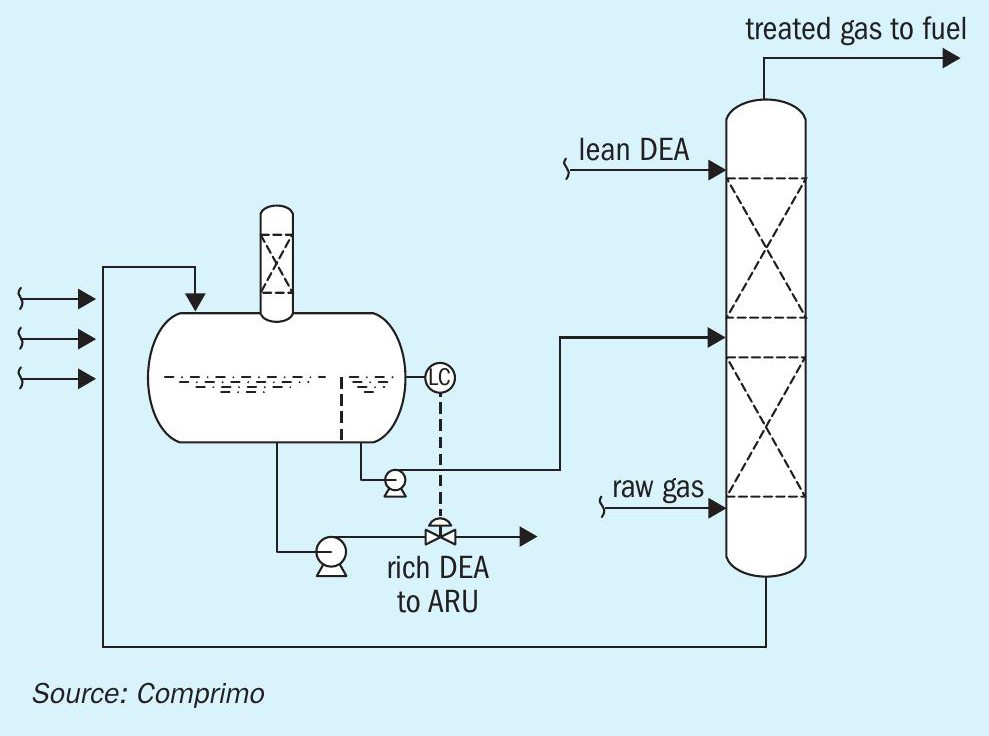
The incident prompted consideration of how to better mitigate major LPG entrainment in the future. Skimming the LPG to slop was ruled out because it would most likely flash to atmosphere in those tanks. It proved a simple matter to inject the stream into the mid-point of an adjacent vapour recovery amine contactor (Fig. 12).
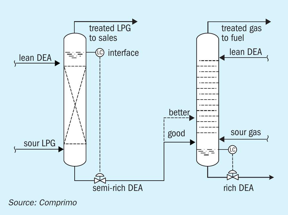
This is analogous to the common practice of pre-flashing rich amine from a liquid treater in a fuel gas contactor (Fig. 13). Since liquid treater rich amine also tends to be under-loaded, further benefit can be achieved by introducing the stream a few trays up from the bottom as shown by the dashed line.
V-Ball Fuel Gas Safety Shutoff Valves
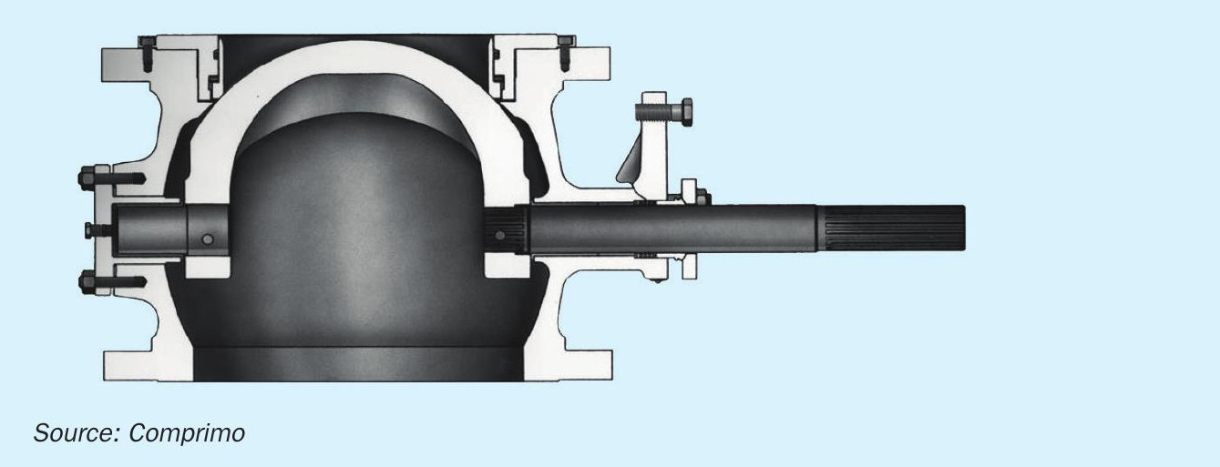
In one typical SRU project, thermal reactor fuel gas safety shutoff valves were specified only as “quarter-turn on/off.” To the casual observer the valves appeared to be ball valves, whereas the vendor had supplied Fisher V-ball valves – possibly for quicker response. The valves passed rigorous tightness tests in the shop, but when the initial field light-off attempt failed, the valves tripped as intended but gas continued to flow.
Following review of the V-ball design it was concluded that, following initial installation, workers had apparently rotated the actuators 180° for better visibility. While this would have made no difference with a conventional ball valve, the V-ball was essentially always open (Fig. 14).
TGTU Methyl Mercaptan
A client operated a BSR Amine TGU using Ucarsol HS-103 which vented un-incinerated tail gas directly to atmosphere as long as residual H2 S was < 10 ppm. They had received several visits from the air quality inspector responding to nuisance odour complaints, and repeatedly assured him they were not the source, since operations were stable with < 5 ppm H2S.
At about the same time, a chance comment by an operator that it “smelled like an animal had crawled into the tail gas line and died” after unplugging the drain led the process engineer to suspect mercaptans. After measuring 40 ppm with a Dräger tube, the reactor inlet was nominally increased from 550°F (288°C) to 570°F (299°C), and the mercaptans went to zero.
In retrospect, the operator’s chance comment bordered on divine intervention. Literature today contains references to such byproduct mercaptan formation, but whether it was common knowledge at the time of this incident some 30+ years ago is unclear. It may have become more apparent as a result of low-temperature catalyst experience.
CS2 is normally hydrolysed to H2S and CO2 in the TGU reactor:
However, it also turns out that CS2 is commercially hydrogenated to methyl mercaptan with a cobalt catalyst at nominally 250°C (482°F) as follows1 , so it is understandable that the mercaptan will form if temperature and/or catalyst activity are insufficient for complete CS2 hydrolysis:
With luck, methyl mercaptan can still be hydrogenated as follows2 :
It is generally known that, as TGU catalyst activity declines with age or abuse, higher temperatures are required for efficient conversion of CO, COS and CS2. It follows that the same applies to mercaptan, and Comprimo has seen residual methyl mercaptan in one unit with overheated and heavily sulphated catalyst at inlet temperatures as high as 650°F (343°C).
Since most plants incinerate tail gas, the potential to make mercaptan may still not be widely known, or even relevant in most cases. A notable exception (in addition to the above example of un-incinerated TGTU tail gas) is the Stretford process where, by analogy to Merox, methyl mercaptan is logically absorbed as the mercaptide and subsequently converted to disulphide oil (DSO) in the oxidisers. Comprimo experience suggests that DSO inhibits froth production, possibly consistent with a comment in Gas Purification – 5th Edition citing such organic sulphur compounds (COS, CS2, mercaptans and thiophene) as having unspecified adverse impact on Stretford operation3.
Commissioning and Murphy’s Law
General advice
New unit start-up advice can be summarised as follows:
- Take nothing for granted.
- Allow no unexpected occurrence to go unexplained – it may be a heads-up. Most potential engineering/construction errors are foreseeable, but occasionally there are once-in-a-lifetime eye-openers.
Continuity of long interconnecting lines
A new SRU received AAG from an off-plot ARU at one location, and SWAG from an off-plot SWS at another location. Operators proceeded to N2 -purge the AAG line from the regenerator to the SRU. While waiting patiently for a sign of flow, the SRU operator noticed vent gas from the SWAG line. What started out as AAG terminated as SWAG, and vice versa.
Debris
An ultra-low-NOx incinerator burner guaranteed to meet 5 ppm NOx could not achieve <15-20 ppm. Process trends suggested the solution was to increase the air/fuel ratio, but the flame became unstable. Following exhaustive troubleshooting to no avail, the manufacturer agreed to replace the burner. In the course of removing the old burner, a bag of desiccant – virtually hidden from view – was found hanging loosely by a cord within the air plenum so as to cause an unstable flow pattern.
Pump rotation
When performance of a turbine-driven recycle water pump proved extremely poor during initial run-in, engineers were stumped until an operator noticed opposing rotation arrows on the pump and driver. Reverse rotation of electric pumps is not unusual because it simply means that power was incorrectly connected, and easily remedied. Turbine mismatch, however, is arguably an inconceivable design error.
Flow direction
The potential for installing check valves backwards is so obvious that it is generally assumed such errors will be caught during punch list execution. In one case the incorrectly welded check valve on the steam from the Waste Heat Boiler was apparently insulated before inspection. The problem was discovered when the PSVs lifted during initial light-off.
On another occasion maintenance personnel were instructed to reverse a check valve. The foreman was later embarrassed when the inspector called attention to the fact that the valve had been re-installed in the same wrong position. Just another reminder to take nothing for granted.
Tail gas butterfly valves
Some butterfly valves have square shafts, making it easy to mount the actuator incorrectly if the valve position is wrong.
On one occasion personnel were stationed at the valve platform to verify proper movement when SRU tail gas valve pairs were simultaneously switched for the first time, with instructions to promptly advise the control room by radio if the closed valve did not start to open as the open valve closed. When the closed valve in fact failed to open, the console operator reversed the hand switch, but the valves failed to respond because the plastic plugs in the actuator air vents had never been removed. The sulphur seals were blown, and the new concrete painted yellow. Lesson learned – hand block sulphur rundowns during switch.
Flow transmitter pressure compensation
Occasionally the pressure compensation signal for measured gas flow will be taken from the wrong transmitter, for example, downstream of the control valve instead of upstream.
Air/fuel-gas ratio
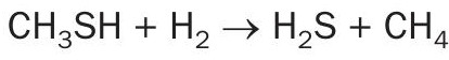
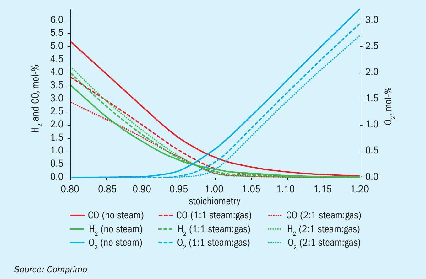
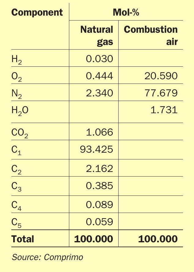
Relative air/gas flow accuracy is particularly critical when fuel gas (including H2 ) will be fired stoichiometrically. Proper air/ gas accuracy should be verified by plotting measured % O2 against air/gas ratio at data points typically ranging from 80% to 120% of stoichiometry, for example. Steam injection will shift the curve due to cooling as seen in theoretical Fig. 15, based on the composition in Table 2.
- In one case meter error grossly understated the TGTU RGG air/gas ratio, resulting in severe sulphation of the presulphurised hydrogenation catalyst upon activation. Lesson learned – shake down burner controls before loading catalyst.
- In another case, overstated thermal reactor air/gas ratio resulted in 10-12% H2 in the flue gas. Since combustion was clean, personnel dismissed the H2 readings as erroneous until the Incinerator burner tripped and the tail gas continued to burn.
References