Nitrogen+Syngas 382 Mar-Apr 2023
31 March 2023
Seeing inside the box
REFORMER MONITORING AND OPTIMISATION
Seeing inside the box
The steam methane reformer is at the heart of most world-scale synthesis gas plants for ammonia, methanol or hydrogen production, and its optimum performance will maximise plant production and efficiency. This article studies the wide variety of parameters that need to be considered if a steam methane reformer is optimised.
Optimising the primary reformer is key to making ammonia as efficiently as possible, with approximately 30% of the total natural gas demand consumed by driving the reforming reaction.
Johnson Matthey (JM) has proprietary models, such as REFORM™ , that take into account many of the parameters that contribute towards this optimisation. However, accessing accurate data has been a barrier to continued optimisation in the field. The use of OnPoint’s ZoloSCAN™ TDLAS (Tunable diode laser absorption spectroscopy) technology makes continuous in-situ flue gas analyses achievable. This article details how, when coupled with process data and Reformer Imager data providing insight into the tube wall temperature profiles across the reformer, it has enabled benefits such as lowering fuel demand, excess air, and therefore NOx emissions and CO2 footprint.
Johnson Matthey’s REFORM modelling package has been utilised as part of a future continuous monitoring system (CMS).
The work has interpreted process data, tube wall temperature data, and thermometric and gas compositional radiant section data. These data streams are used together to develop new insights into what is happening inside a reformer cell. This creates an opportunity for improved reformer optimisation.
The work referred to as REFORM CMS was led by Johnson Matthey in partnership with OnPoint Digital Solutions LLC and delivered to Yara Le Havre, who pioneered the system’s use.
The benefits of the REFORM CMS work include:
- Improved plant reliability – enhancement of asset integrity programs.
- Improved ammonia production efficiency – optimisation of hydrogen production.
- Maximised furnace efficiency – optimisation of excess air.
- Enablement of continuous improvement culture by translating information into knowledge and supporting the implementation of improvement actions.
- Improved plant safety – minimise risk of unwanted tube failure.
Background
Steam methane reforming has been used as an industrial means to realise hydrogen since the 1920s. Over the last hundred years, our understanding of this process has grown enormously, enabling developments that make it possible to reform a wide range of hydrocarbons in various licensed reformer designs. However, many reformers operate without the ability to measure and optimise all the parameters that affect their operation.
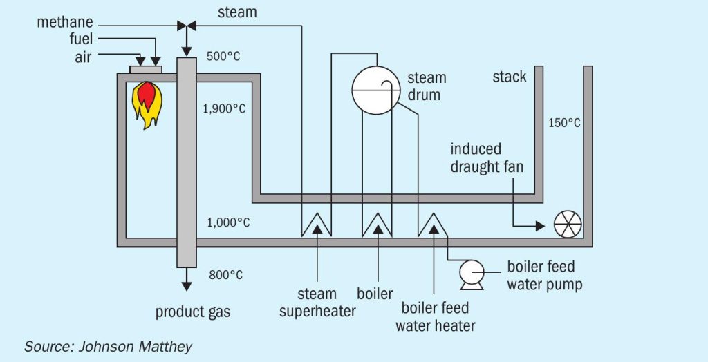
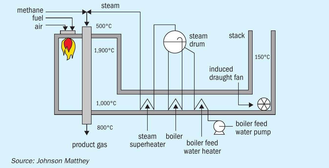
The steam reforming process reacts purified hydrocarbon feedstocks with steam to produce hydrogen and carbon oxides. In the reformer, a series of interconnecting reactions take place over the catalyst. The two hydrogen forming reactions, steam methane reforming and water-gas shift are detailed below:
Following reaction (1), process conditions can be optimised to maximise the conversion of methane, at equilibrium, by higher temperature, lower system pressure and increased steam partial pressure.
As shown in reaction (1), steam methane reforming is strongly endothermic and large quantities of heat are required to drive the reaction to the hydrogen product. To provide the process heat to overcome the heat of reaction, a reformer is designed to hold the catalyst within tubes in a furnace.
This combination of catalytically driven reaction and furnace operation results in one of the most complex process units on the ammonia plant. Much technical knowhow and insight is required to ensure safe and efficient operation across the reformer. Reference 1 describes in detail some of the issues that can arise from the sub-optimal operation of a reformer, including:
- Inefficient operation: Poor conversion of hydrocarbon feedstock, poor use of fuel.
- Tube rupture: During normal operation, the tubes are within the creep region and have a limited lifetime. Operation at higher temperatures significantly reduces tubes’ lifetime; if this is exceeded, the tubes can rupture within the reformer, with the potential for a serious incident2 .
- Carbon formation: High temperatures or catalyst poisoning can result in formation of solid carbon on the catalyst and within the tubes. This will reduce catalyst activity and increase pressure drop up to blocking tubes3 .
The carbon forming reactions and much more are included in REFORM, Johnson Matthey’s proprietary software for modelling the operation of steam reformers. It was initially developed by ICI in the 1960s to support their steam reformer operation, and since then has been continually improved and updated with more detailed models and to reflect changing reformer design4 . REFORM is a powerful tool to design the catalyst loading, evaluate current operating performance and assess optimised operating conditions.
Previously, when optimising a steam reformer, the process was limited by the amount of data available and the one-time nature of the data-collection process. Tube wall temperature (TWT) data would be collected manually and operation optimisation would be carried out based on this data. However, over timeperhaps a few days or weeksplant operating parameters would change, and plant operation would become sub-optimal.
The REFORM CMS work addresses this issue by considering a wide range of continuous data, covering many aspects of steam reformer operation. If the plant operation is required to change, updated TWT data can be gathered and analysed quickly. This allows timely re-optimisation and maximises the time spent at peak operation5 .
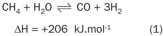
REFORM CMS work considers three differentiated data feeds, each targeted to supply a data input that drives the REFORM model: TWT, process and radiant box data, as depicted in Fig. 2.
This allows the operator to understand:
- where there is an opportunity cost;
- which process parameters to target to optimise the operation.
The following sections describe how REFORM CMS was deployed, looking at the components, installation and interoperation of the first data.
Components of REFORM CMS
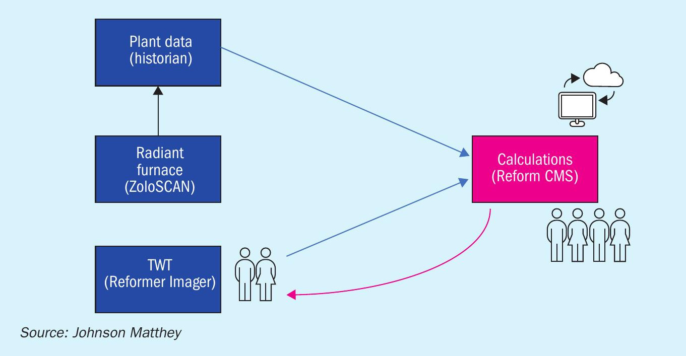
The data fed to the REFORM CMS work comprises three separate streams: plant data (pressures, temperatures, gas compositions, etc.), Reformer Imager data of TWT for the tubes and ZoloSCAN TDLAS data for the radiant box.
In Fig. 3, the data collection activities at the client site are shown in dark blue. They provide data input for analysis and reporting, shown in pink.
In comparison to a typical plant data set, REFORM CMS work considers:
- more of the parameters affecting the reforming operation;
- more granularity within the data, as it is not a global average. Data can be used to define different conditions across the reformer cell.
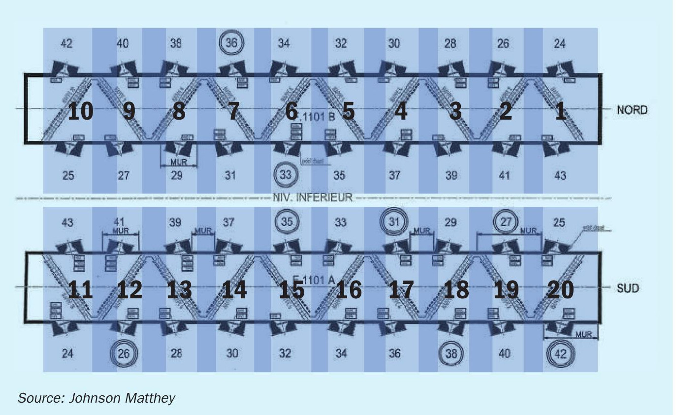
In the case of the Yara Le Havre reformer, the tubes are arranged in diagonal rows laid out in an unusual sawtooth pattern in each of two reformer cells (north/south), as shown in Fig. 4.
For modelling purposes, each cell was split into 10 ‘mini reformers’ or sub-cells4. This required:
- plant data to provide process temperatures for the outlet header of each tube row;
- Reformer Imager TWT data for each tube;
- ZoloSCAN TDLAS temperature data for the radiant cell in the vicinity of each tube row.
Plant data
Plant data is already utilised regularly by the operations team in the safe running of the unit. It is also commonly used every few months to provide a snapshot that is utilised in data evaluations to assess the effectiveness of the process in the context of the reformer operation.
Secure file transfer protocol (SFTP) captures and transmits a comprehensive set of process data from the Yara Le Havre historian to JM.
This provides the required detailed process data:
- inlet gas composition;
- inlet process gas pressure;
- inlet process gas temperature;
- inlet gas flow; l temperatures of each collector header;
- exit process gas pressure;
- exit gas composition.
This provides a platform for regular data transfer and the daily data processing using the optimisation tools developed for the REFORM CMS work. Using high-quality, consistent data allows the analysis to look beyond a global average.
Tube wall temperature data
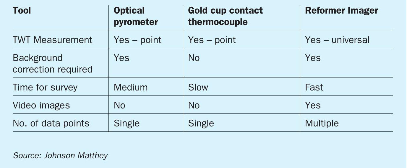
A standard visual inspection of the furnace is invaluable but gathering quantitative data on the TWT spread across the furnace is essential. There are three commonly employed pieces of equipment to measure TWTs; each option has its merits. Table 1 gives a summary of how these different reformer measurement devices function.
Based on these properties, the Reformer Imager has been selected to gather TWT data.
The Reformer Imager supplied by LAND Instruments International Ltd. and developed as a portable reformer survey tool by JM provides more insight into the TWTs than any other available method.
The Reformer Imager can measure temperatures in the range of 600-1,100°C, and the measurement wavelength of 1 mm maximises visibility through the hot combustion gases. The Reformer Imager provides a wide viewing angle, so often almost all of a tube row can be seen in one video image, which is more than can be seen visually. The videos are recorded directly to a laptop and can be used for further analysis. For more information on the technical specifications and capabilities of the Reformer Imager, see Reference 6.
During a standard Johnson Matthey reformer survey using the Reformer Imager, data is gathered by manually moving it through different planes to capture as much of the reformer as possible. However, the natural variation resulting from this type of movement means that each video must be interpreted manually. This can be very resource-intensive, and the interpretation of videos can often take several days of effort. As Reformer Imager surveys are not often carried out, this time is appropriate.
However, for the REFORM CMS work to be truly continuous, there was a need to enable more regular TWT data collections and interpretation with a quick turnaround. This need led JM to further develop the use of the Reformer Imager as a portable reformer survey tool and to include automation to speed up data extraction. To improve repeatability, a clamp was developed to hold and manipulate the Reformer Imager, rotating it in the same manner in every peephole while the thermometric video data was captured. The benefits of this are:
- consistent positioning is achieved in each peephole;
- consistent movement takes place at every peephole;
- improved automation of data extraction.
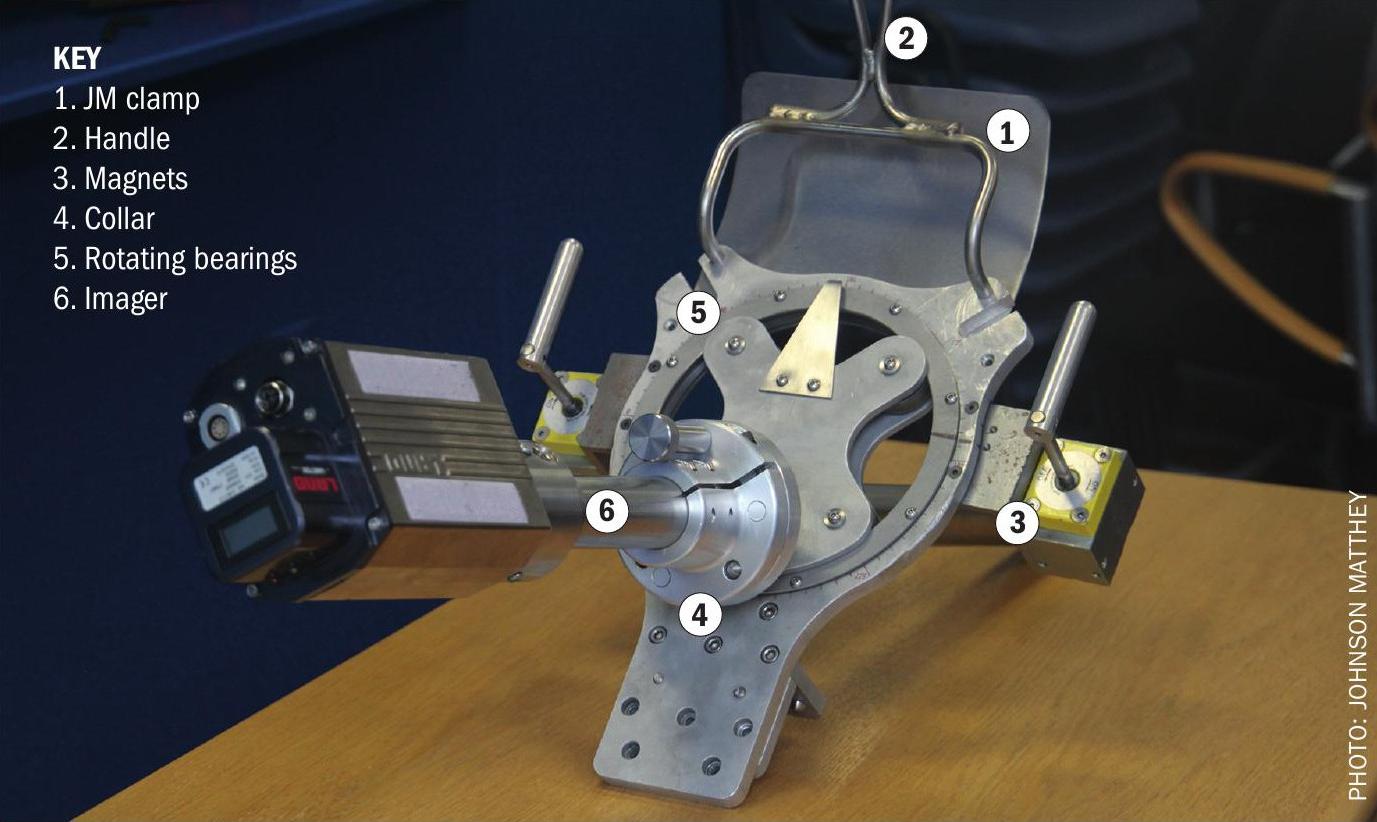
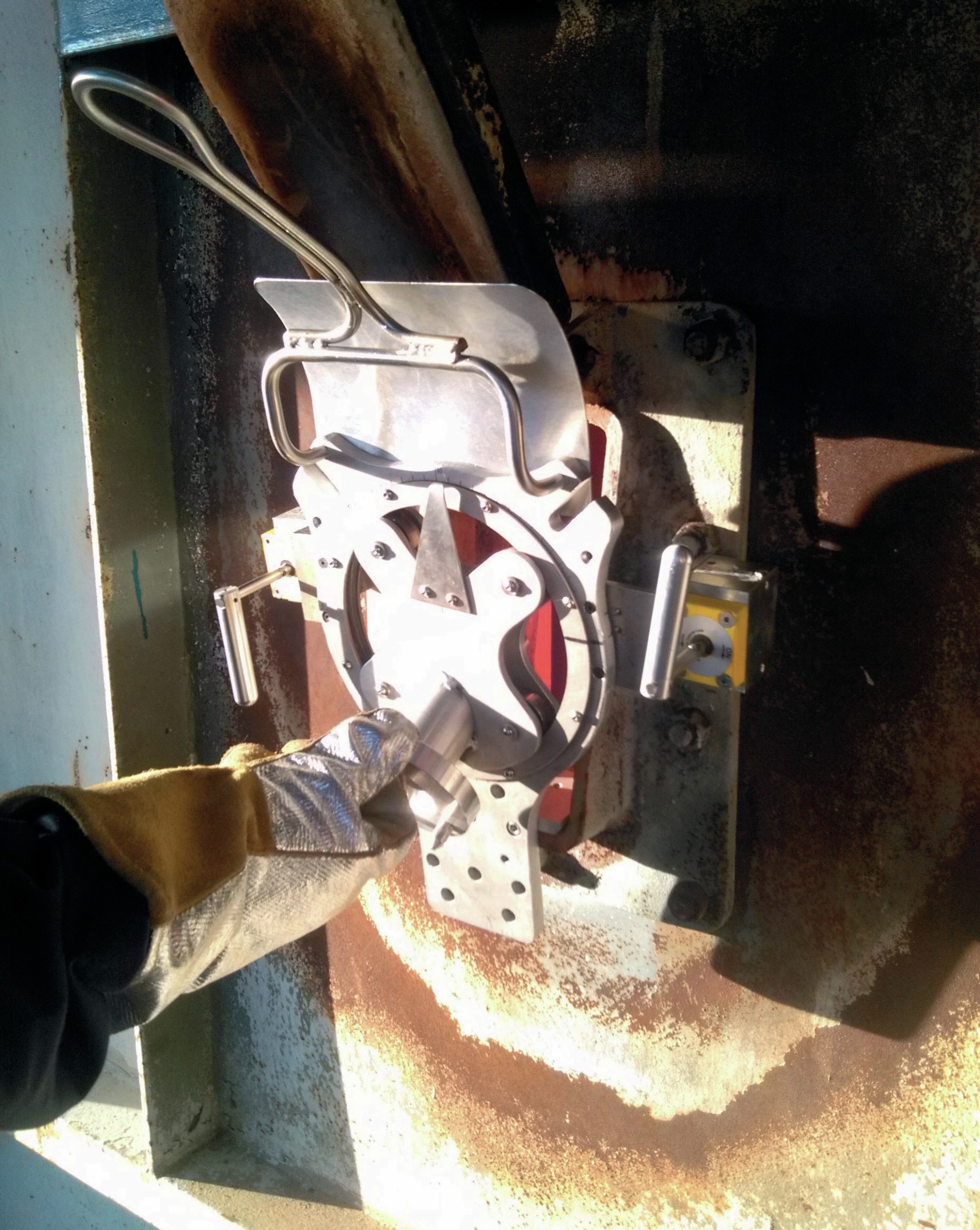
The picture in Fig. 5 shows the Reformer Imager positioned in the JM clamp. The clamp provides a collar located within a rotating set of bearings, enabling the Reformer Imager to be rotated through 360°. The clamp is lifted using the handle. The feet rest on the bottom of the peephole, and magnets aid in stability during use by providing easily reversible adhesion to the outer wall of the furnace7.
A wireless bridge is used to avoid the need for a wired data transfer connection between the Reformer Imager and the laptop. A single battery powers both the Reformer Imager and the bridge. This wireless enablement of the Reformer Imager brings multiple benefits:
- removes tripping hazard of the data transfer cable;
- improved connection reliability;
- decreases the time to complete a TWT survey.
TWT data extraction
The streamlining of the data extraction process was enabled by the consistency gained from the use of the JM clamp. The video captured as the Reformer Imager is rotated in the clamp is first stitched to form a single, complete image, and then TWT data is extracted from this image.
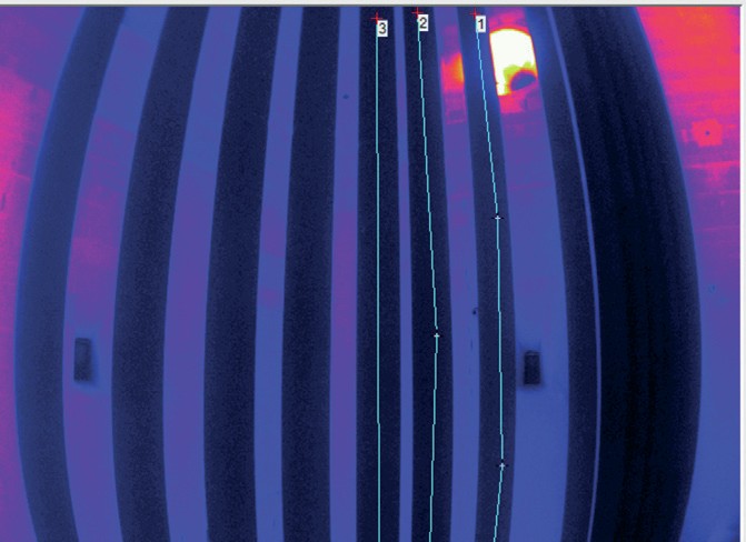
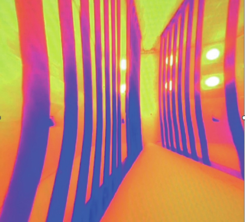
Fig. 6 shows a still image from a video recorded by the reformer imager, displaying a partial view of the tubes within the furnace.
Stitching the individual images that make up the video into a single composite image provides the greatest possible field of view from the peephole without having to view and select multiple frames from video manually. This can be seen in the composite image in Fig. 7, which shows many more of the tubes than the image in Fig. 6.
The single composite still image can now be processed to extract the thermometric data. This extraction has been semi-automated, with the potential to fully automate this process.
The requirement for background radiation correction was tailored for the reformer at Yara Le Havre and managed as part of the data interpretation.
Multiplexed ZoloSCAN TDLAS system
The third data stream was provided by OnPoint’s multiplexed ZoloSCAN TDLAS system. This system monitors and describes the gas composition and temperature within the radiant box.
TDLAS measurements are based on molecules, each having a unique signature absorbance profile. An industry standard diode laser is tuned in wavelength across a tiny portion of the optical spectrum. A given combustion component absorbs light at the chosen wavelength, and the relative amount of absorption is proportional to the concentration of that component.
OnPoint’s multiplexed ZoloSCAN TDLAS technology transmits multiple laser wavelengths simultaneously along a single path and measures an average across each path for each component simultaneously. This provides real-time, in-situ measurement of temperature, O2 and CO directly in the reformer combustion zone. The path layout also provides spatial representation profiles of temperature, O2 , and CO. The path layout was defined as it provided a path average data source into REFORM for each sub-cell.
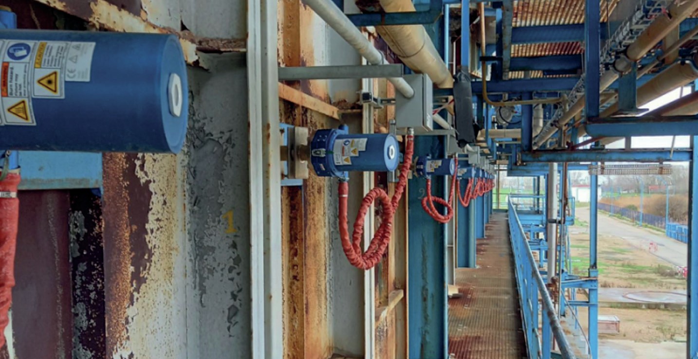
The ZoloSCAN system for Yara Le Havre was designed to provide 22 laser paths across the reformer cells, with transmitting heads termed “pitch” and receiver heads termed “catch” mounted on the outer walls of the furnace as shown in Fig. 8.
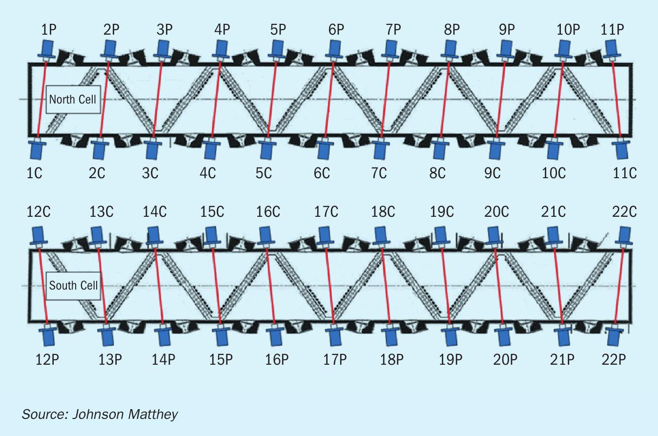
Each pitch head periodically emits the combined laser light sources to the catch head maintaining alignment automatically and continuously. The light source transits across the reformer cell, following a path not impeded by the reformer tubes. Further focusing is enabled during operation using a steerable optic assembly within heads to maximise the signal strength. The path design places laser paths between the herringbone arrangement of tube rows, so data is gathered associated to each row of tubes.
Installation of tools needed for the REFORM CMS work
Project implementation was hindered by the Covid-19 pandemic, which delayed the installation of the ZoloSCAN system, a key component, for many months. It took nearly 18 months to achieve project implementation, although the active working time was approximately three months.
Plant data
This was the easiest part of the installation. Clearly, the plant data already existed and was recorded by the historian. Yara and JM agreed on which instrument data were needed to model the reforming operation and prepared a list of associated instrument tag numbers. JM provided a SFTP connection, and data transmittal started.
Reformer Imager
The work required the development of the Reformer Imager clamp and wireless enablement of the Reformer Imager to avoid the communications cable becoming tangled.
Achieving consistency: The clamp
The clamp was developed over several iterations, offering a bespoke design to integrate with the reformer peephole design employed at Yara Le Havre (Fig. 9).
Multiplexed ZoloSCAN TDLAS
The heads were mounted on sight tubes that had previously been fitted to the reformer during planned maintenance (Fig. 10). These provided alignment between the pitch and catch heads. The sensor heads were then able to be fitted while the reformer was in operation, minimising the required downtime.
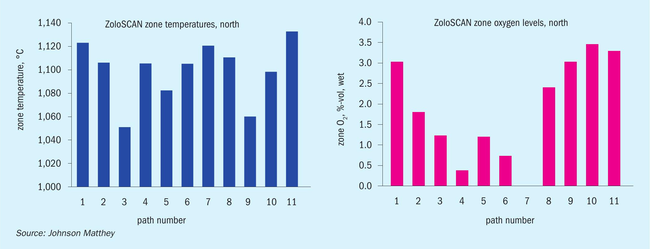
The output from the ZoloSCAN TDLAS can be read directly from the historian, as shown in Fig. 11, or through the REFORM CMS dashboard.
Training
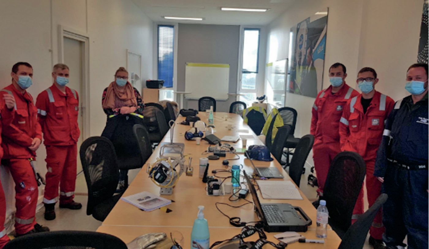
JM provided training to Yara Le Havre covering the functions of the REFORM CMS work, practical use of the Reformer Imager and use of the thermometric analysis method for the captured videos (Fig. 12). OnPoint provided full training in the use of the ZoloSCAN TDLAS system.
Use of REFORM CMS
Primary actions
Integration with the existing Yara Le Harve asset integrity program is of paramount importance. The TWT data is mapped (see Fig. 13), showing tubes that are too hot or too cold. To protect the tubes, the first action is to reduce the temperature of the hottest tubes based upon this data.
Secondary actions
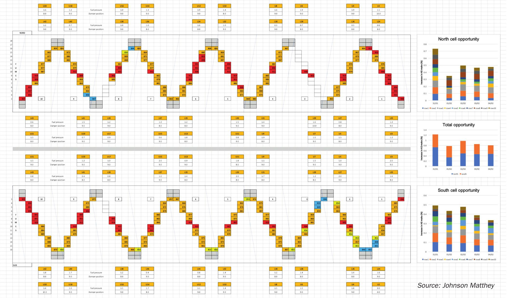
REFORM CMS runs are based on each day’s process and TDLAS data for each sub-section of the reformer cell. It produces key performance indicators (KPIs) for each sub-cell, such as measured and optimised values for the:
- tube exit temperatures;
- approach to equilibrium (ATE) for the reforming reaction;
- hydrogen make;
- excess oxygen in the flue gas.
The dashboard visualises the opportunity value for hydrogen make and excess oxygen. The opportunities are presented as a global value and broken out to show which zones present the best opportunity for improvement and which section of the furnace should be the focus. The basis of the optimisation is to:
- reduce TWT variation and move the average toward the optimal value, thereby producing most hydrogen.
- move excess oxygen toward a decreasing and agreed value. The effect of this is to move the unit away from the fan limit in the duct and directionally lower the NOx in the flue gas.
Benefits of REFORM CMS
Benefits can be measured in several ways, including:
- TWT reduction of hottest tubes, providing an extension of tube life;
- increased product make from the same feed natural gas flow.
These benefits are easily monitored by following the trends provided in the REFORM CMS dashboard, along with the excess oxygen. Other less quantitative, but still crucial benefits include:
- increased number of focused discussions on reformer optimisation, with data to back these up;
- increased number of adjustments and interventions to optimise performance.
Future for REFORM CMS
Several short-term innovations have further improved the technology and thus could for allow wider implementation of REFORM CMS:
- the new ZoloSCAN2 system will help reduce the cost of an installation as the SensAlign™ heads can be affixed to existing peephole doors. This avoids the need of a reformer outage for installation of the system;
- continued improvements in Reformer Imager technologies and data collection methods. This would reduce the operator time for data collection and speed up data processing;
- addition of online gas analysis to allow real-time reformer ATE calculation.
Conclusions
The REFORM CMS work shows the potential opportunity from daily analysis of reformer performance and associated optimisation. The system has been constructed to respond quickly to changes in rate, feed composition, etc., to re-optimise performance. Reformer Imager data affords assurance from an asset integrity perspective before and after a change is made. This project has shown the interconnectivity between the process data, the TWT and the combustion cell conditions. Only when all three of these are considered can the operator truly “see inside the box.” n
Acknowledgements
The authors wish to thank the staff at Yara Le Havre for their support and contributions. Mike Davies, Kate McFarlane and Carl Hamlett at Johnson Matthey have provided essential expertise and insight for this project.
References