Sulphur 405 Mar-Apr 2023
31 March 2023
Sneaky SO2 breakthroughs
CLAUS TAIL GAS TREATING
Sneaky SO2 breakthroughs
SO2 breakthroughs remain an ever present threat to the successful operation of reductive, quenchamine-based tail gas clean-up units (TGUs). Effects can range from mild and annoying to quite severe, including failure to comply with environmental permit regulations and refinery shutdown. G. Simon A. Weiland, Nathan A. Hatcher, Prashanth Chandran, Daryl Jensen, Ralph H. Weiland, Jeff Weinfeld of Optimized Gas Treating, Inc. and Michael Huffmaster, Consultant.
It has been shown that SO2 breakthroughs are one of the most damaging and devastating process upset events that can occur within a sulphur processing unit. The damage, if not caught and mitigated in time, can include both the quench water loop and TGU amine section. Of the extensive list of problems that can occur, corrosion and plugging are the most common for the quench water loop while solvent degradation and loss of selectivity leading to high CO2 recycle rates are most common if the problem is severe enough to make it into the TGU amine section. In a refinement to work conducted by OGT in 2016 and focused on the effects of these breakthroughs on the downstream equipment, this article assesses the way aged and poisoned Co/Mo catalyst can increase the risk of SO2 breakthroughs. A plausible explanation for chronic, low-level SO2 ingress into a quench column that happened off and on at one facility for many years is demonstrated through a newly available kinetic hydrogenation reactor block in the SulphurPro® simulator. With this work, OGT hopes to raise awareness in the industry for other facilities with SCOT-type TGUs by looking more specifically at how these upsets occur in the first place. The hydrogenation reactor is the main equipment item responsible for converting SO2 back into H2S which the downstream amine unit can then absorb and recycle to the front of the sulphur recovery unit (SRU).
Process background
Understanding how an SO2 breakthrough can occur in an SRU requires a basic understanding of the overall process and the path that sulphur takes. The sulphur recovery complex in a refinery or gas plant is visualised as part of the overall system for extracting H2S as well as other acid gases and organic sulphur compounds from the product stream. The acid gases (which include H2S) are extracted and produce a generally concentrated H2 S stream. This H2S-rich stream is then fed to an SRU which consists of Claus-type sulphur conversion, a tail gas unit (TGU), and a thermal oxidiser (TO) before the gas is then vented to the atmosphere. The sulphur compounds are recovered as elemental sulphur and, because these systems are not 100% efficient, the small remainder that is not recovered is emitted to the atmosphere.
The fundamental Claus chemistry converts H2S into elemental sulphur through a thermal stage and two or three catalytic stages with around 95–97% efficiency:
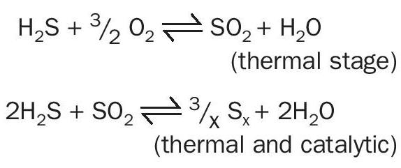
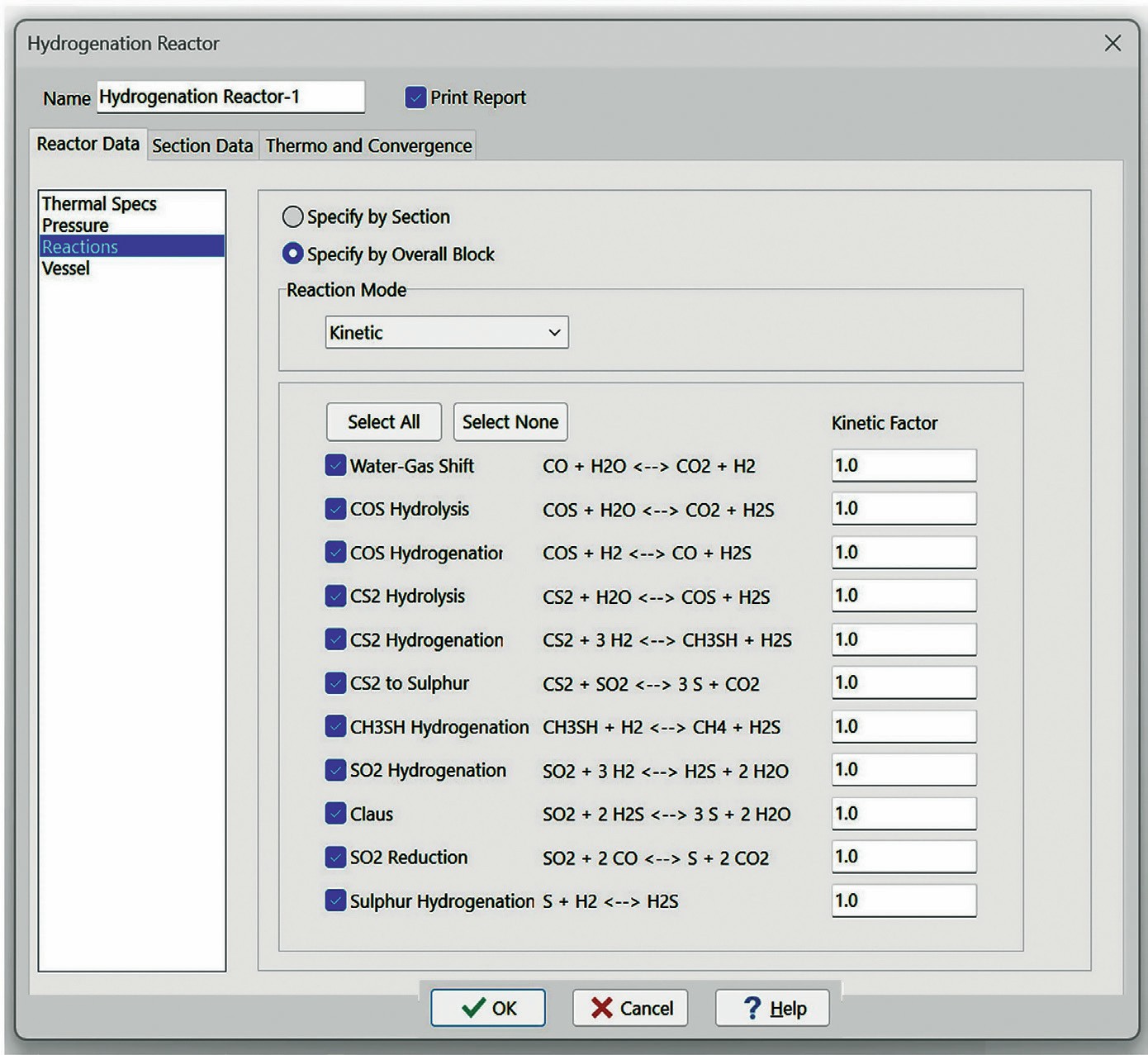
The TGU processes the off-gas from the SRU which helps to meet the tight sulphur recovery requirements of today’s environmental standards. The TGU consists of a multi-step process where the off-gas from the SRU is first passed through a catalyst bed, where the hydrogenous conversion of non-H2S sulphur species to H2S occurs. This catalytic stage is also responsible for continuing the Claus process and it water-gas shifts carbon monoxide into hydrogen which helps the hydrogenation reactions along with reducing CO emissions. In the hydrogenation reactor the main sets of reactants in the reactor are:
- COS, CS2 – hydrolysis on alumina catalyst
- SO2 , Sx , COS, CS2 – hydrogenation on Co/Mo catalyst
- CO – water gas shift on Co/Mo catalyst
The actual process chemistry is complex consisting of several parallel reactions and reactions between SO2 and other reduced sulphur species to be discussed later.
The next step in the TGU is quenching the hot gas produced from the hydrogenation reactor. This step not only cools the hot gas but removes much of the water that is produced as a by-product from the Claus reactions. This is the first line of defence when facing an SO2 breakthrough. The pH of the quench water is monitored, and caustic (or sometimes ammonia) is injected when the pH drops below a certain threshold in order to neutralise and absorb the acidic SO2 before it makes its way to the next section of the TGU, the amine circuit.
The amine circuit of a TGU aims to absorb H2S selectively while letting CO2 continue out of the absorber with the remainder of the gas. The H2S absorbed is then sent to the amine regenerator where the H2S is stripped out of the solvent and returned back to the front of the SRU. The addition of a TGU to an SRU can give an overall recovery performance of >99.9% efficiency (depending on the amine and the general operation of the amine circuit).
A critical performance requirement for the catalyst used in the hydrogenation reactor is that SO2 should be fully converted to prevent residual SO2 from entering the quench circuit where fouling, corrosion, and (if severe enough to make it to the amine circuit) deactivation and degradation of the amine selectivity occur. High conversion of COS, CS2, and mercaptans are also required as the hydrogenation reactor is the last line of defence for these compounds before these sulphurous species are vented to the atmosphere. Amines generally have very little affinity towards these non-H2S compounds and, as such, will not remove much (if any) from the gas stream.
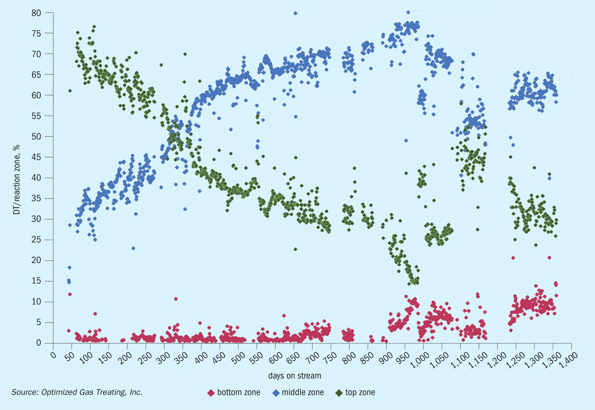
A temperature profile across the TGU reactor is commonly used to provide insight into catalyst performance and health. Fig. 1 presents operating data for a typical refinery TGU reactor showing the temperature profile across a four-year operating window4 . The adiabatic reactor experiences a total temperature rise, DT, from the exothermic reactions associated with conversion of various sulphur species to H2S and shift of carbon monoxide to hydrogen. Three approximately equal segments of the bed are shown with their respective percentages of overall temperature rise across the bed: top zone (green) shows 70% of DT, middle zone (blue) shows 30% DT, and bottom zone (red) shows negligible DT. Fresh catalyst achieves almost complete conversion in the first two zones.
The overall temperature rise across the bed is virtually constant across time (not shown), reflecting that even with sulphur slip as outlet concentrations of non-H2S species increase, there is still high percentage conversion. The size of the temperature rise is related primarily to the concentration of sulphur dioxide, carbon monoxide, and elemental sulphur in the feed. The relative temperature rise in each zone reflects its degree of conversion.
OGT | SulphurPro® hydrogenation reactor model
The model implemented into SulphurPro is a kinetic-rate model and takes into account several key factors. The reaction set includes not only major reactions but also the parallel side reactions. The kinetic rate model has been fitted to experimental data, and a key part of the model is the inclusion of catalyst aging and poisoning because catalyst activity determines reactor performance, and deactivation occurs through aging and poisoning. The gradual loss of catalytic rate is inevitable and must be fully accounted for and addressed in the initial design of the TGU.
Activity decline as a function of time and exposure to normal process conditions is related to loss of surface area and active sites and is treated as aging. The fractional active surface area can be represented as an aging factor. Aging tends to occur uniformly throughout the catalyst bed, with catalytic activity or conversion of reactive species declining rapidly at first and then slowly over catalyst lifetime.
Poisoning is treated as activity loss related to any of several contaminants in the feed. The causes include:
- chemisorption of strongly interactive species;
- reactive contaminants modifying active metal sites, alumina support;
- oxygen slip from burner mal-operation; fouling, soot, or sulphur formation;
- coking;
- sintering, base structure transformation, or even mechanical damage.
Certain streams which wind up at the TGU are known to contribute to poisoning. Although not ideal for an SRU, using the SRU for waste disposal is sometimes taken to be of least consequence. Wastes include:
- reformer hydrogen as supplemental hydrogen – source of BTEX or chlorides;
- refinery gas as reducing gas generator (RGG) fuel – source of BTEX, olefins, heavier hydrocarbon plus variable heating value which aggravates RGG sooting or oxygen slip;
- acid gas enrichment (AGE) off-gas – usually contains heavier hydrocarbons and BTEX.
The model developed and implemented into SulphurPro accounts for both aging and poisoning as decline functions that necessitate providing the service run time of the catalyst and the poisoning stresses present in the individual configuration of the particular SRU.
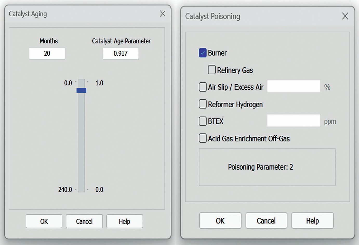
The different configurable poisoning factors include options to specify the use of a RGG burner, refinery gas as the fuel source for the burner, reformer hydrogen, whether the unit process off gas from an acid gas enrichment unit, specifying how much (if any) BTEX is in the feed, and how much excess air is present. Each of these options contributes to a poisoning factor that is built into the mathematical framework of the catalyst bed. A much more detailed analysis and explanation for the model can be found in Huffmaster, et al1 .
Figs 2 and 3 show the interface for the reaction set and for catalyst aging and poisoning.
Case study introduction
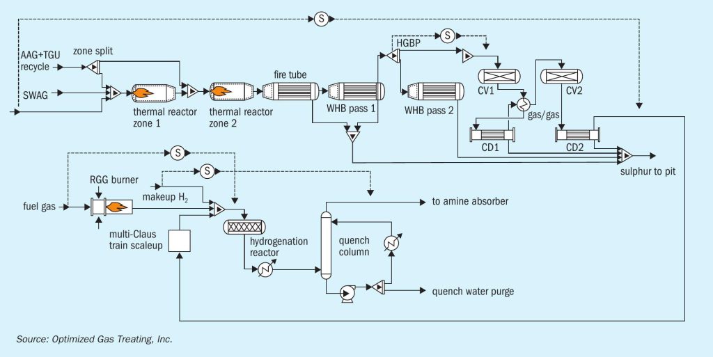
The case study is based on an operating refinery in North America. The SRU processed both high-quality, amine, acid-gas (AAG), as well as sour-water, acid gas (SWAG), as shown in Fig. 4.

The main complaint of the operating personnel was that SO2 breakthrough-like symptoms were observed for years through cloudy quench water, frequently plugged and bypassed quench water filter elements, and thiosulphates in the downstream TGU amine section. However, despite their best efforts, the plant was never able to detect any SO2 in the feed gas entering the quench column even with the help of expert, specialised, analytical testers brought in to help troubleshoot. The general conclusion was that either there were intermittent, low-level amounts of SO2 being slipped or there was some amount of gas bypassing the reactor. To get a deeper understanding of how SO2 breakthroughs occur and try to pinpoint what might be going on in this particular plant, a set of case studies was performed to gauge how small changes in the operating condition of the SRU affect the performance of the TGU hydrogenation reactor.
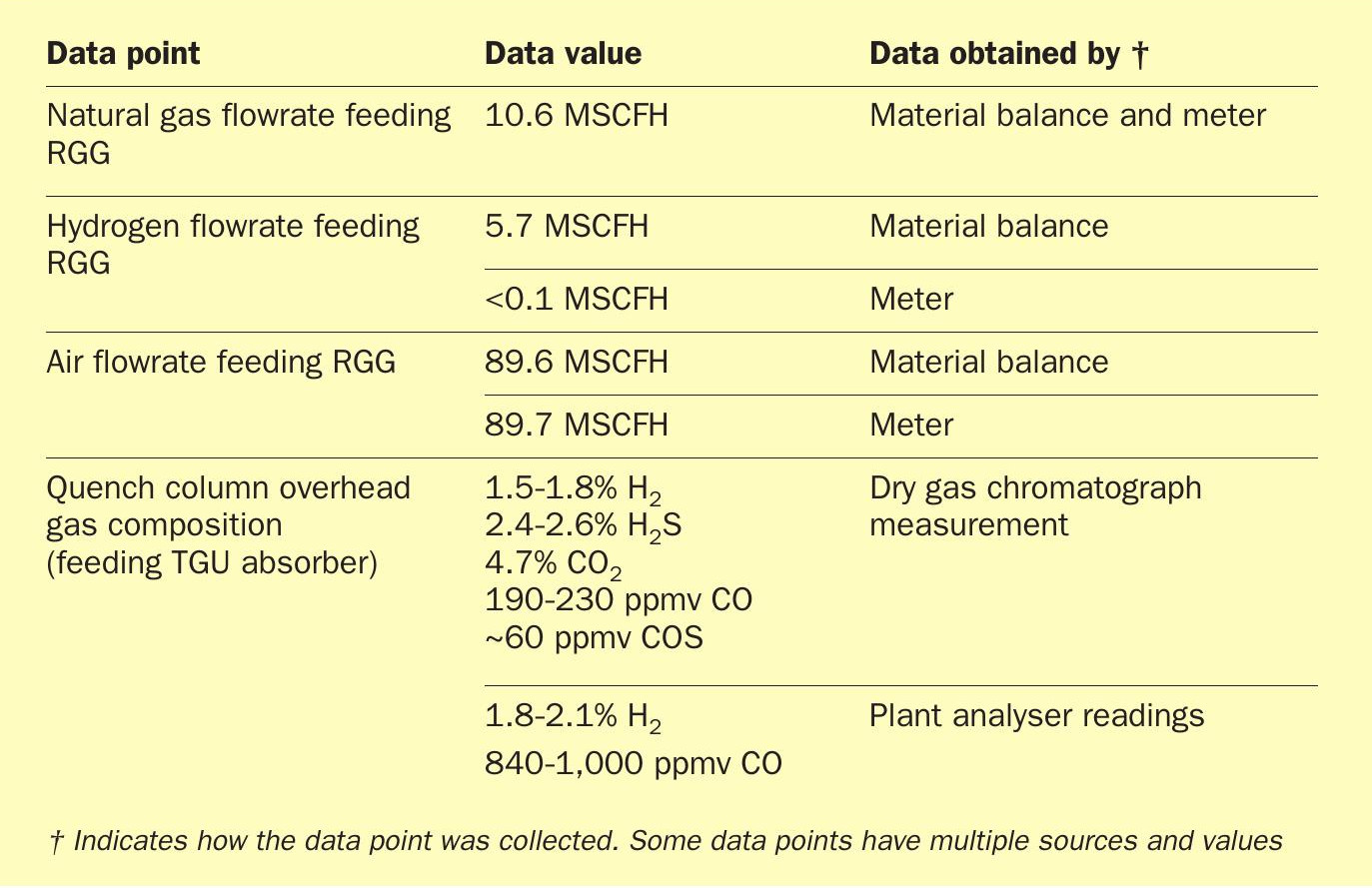
Since the focus was on how the operation of the upstream SRU affects the performance of the TGU hydrogenation reactor, the downstream amine section of the TGU (amine contactor and regenerator) was omitted from the simulation to shorten convergence time and reduce unnecessary interference. The base case was established using test run data provided by the operating plant (Table 1) with the catalyst age set to the specific number of months the catalyst bed had been in operation (this controls the hydrothermal aging of the catalyst) and the specific poisoning agents that the catalyst bed had seen.
Careful comparison was made between the test run CO/COS data and the bed temperature profiles to ensure the model was an accurate representation of the plant performance at the time of the snapshot. Once the model was validated, upset conditions were simulated by placing the Claus air on manual and stepwise increasing its flowrate. During this simulated upset, it was assumed that the hydrogen analysers were either malfunctioning, blocked in, or were ignored by operations. It was also assumed that the rapid caustic or ammonia injection for quench pH control was delayed or not done properly. For this set of case studies, process variables were monitored for signs of damage and indications of an SO2 breakthrough.
Case study findings
The initial simulation of the base case used several iterations to reconcile the model and plant data. Fig. 5 shows how the data (solid points) experience a fairly sharp drop before the exotherm approximately halfway through the reactor bed. As shown by the dashed line, simply modelling this using a hydrothermal-aging-only model does not really capture the nature of this temperature profile and is clearly missing something. Adding the poisoning model to the overall bed calculations (solid line) shows results more closely aligned with the top-down deactivation shown by the actual operating data.
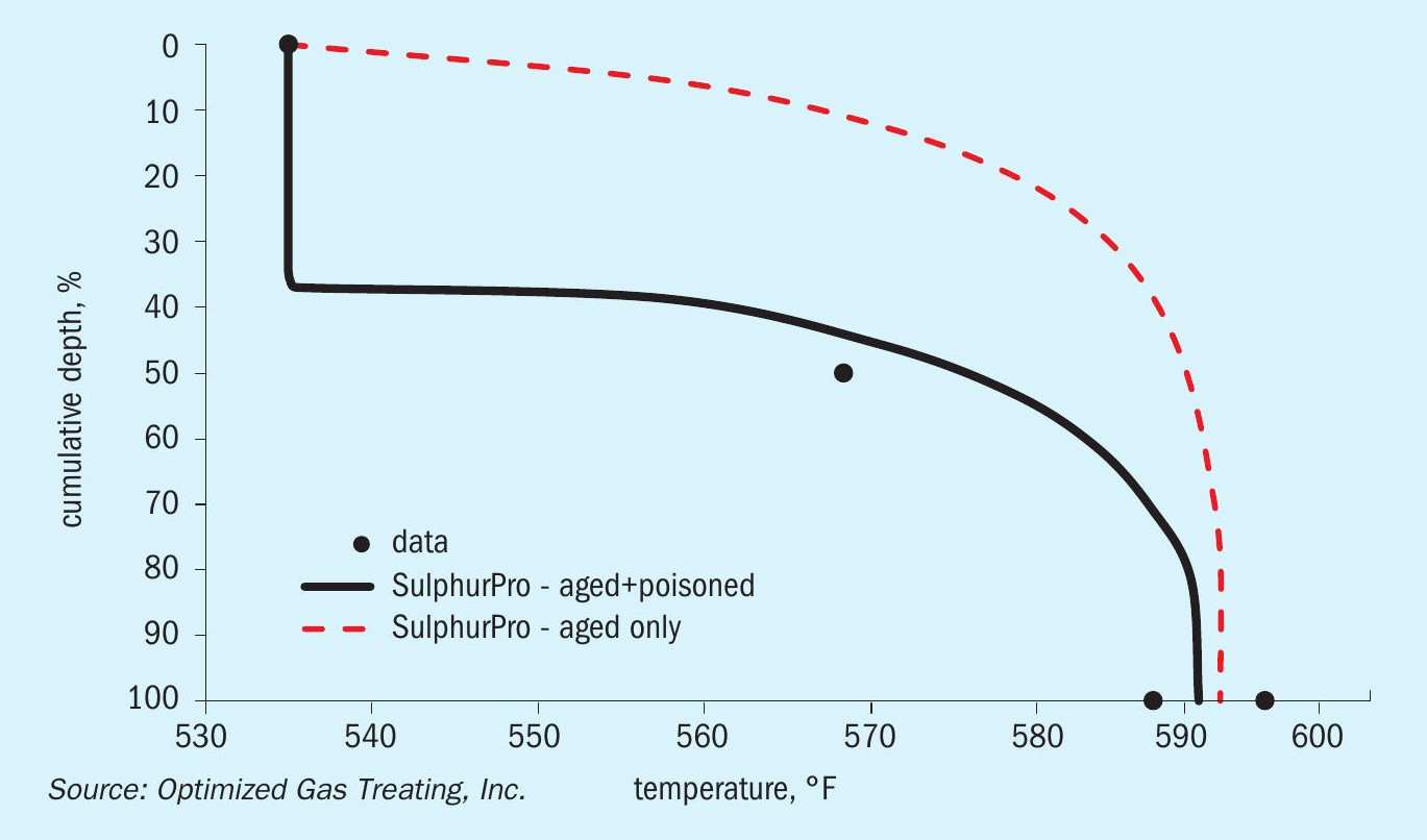
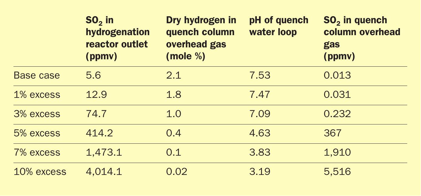
Having established a representative case, the model showed that with the given test run data, there were 2-11 ppmv of SO2 slipping from the hydrogenation reactor through to the quench column. This varied depending on the poisoning agents from the poor-quality reducing hydrogen assumed in the plant and the model. The amount of hydrogen in the quench overhead was right at the desired 2.0% level and certainly did not indicate anything was going wrong with the hydrogenation reactor. Even as the excess air was increased by 1% over the base case, excess hydrogen in the quench overhead did not drop very much even though the amount of SO2 slipping more than doubled. Because of the aging and poisoning of the catalyst, even with excess hydrogen, non-zero levels of SO2 were exiting the hydrogenation reactor and entering the quench loop.
Because this is a refinery, the SRU is processing ammonia, which inevitably slips through the Claus unit in small quantities and ends up in the quench water loop downstream. This ammonia in the quench water loop acts as a buffer to counteract trace quantities of SO2 that escape from the hydrogenation reactor, but only to an extent. The small amount being slipped in the base case, and even at 1% excess air, was well within the range of buffering capacity of the ammonia in this instance. However, even a small upset of 5% or more excess air exceeds the ammonia’s buffering capacity in the quench water loop and begins to send 100+ ppmv SO2 through to the amine system. If left untreated for any appreciable length of time, this has devastating effects on the health of the amine solvent and the equipment.
The baseline pH of quench water varies depending on the source of the sulphur being processed. Refinery SRUs generally process ammonia and have fairly low levels of CO2 in the feed gas so the pH generally is 7-9 because ammonia builds in the quench loop. Gas plants, on the other hand, generally have lower quality feed gas containing higher levels of CO2 and do not generally process ammonia. CO2 does not participate in the Claus reaction so it will have some (acidic) accumulation in the quench water which also lacks buffering ammonia. The result is pH in the range 5-7. In this particular case, the baseline pH of the quench water was around 7.5 which is right in line with the expected 7-9 range. As the amount of SO2 slip from the hydrogenation reactor increases, the buffering ammonia prevents pH from dropping very sharply, so pH was not a good indicator of an SO2 breakthrough.
As Table 2 shows, the amount of SO2 slipping through the reactor exponentially increases with small step changes in the amount of excess air feeding the unit. In the base case (and even the 1% excess-air case), this small amount of SO2 would be undetectable even with the sophisticated equipment of the some of the analytical companies.
Conclusions
In the case study presented, the OGT | SulphurPro® model suggests that the plant is experiencing a chronic SO2 leak due to the aged and poisoned hydrogenation catalyst. This was undoubtably the result of heavy hydrocarbons in the makeup reformer hydrogen. Over the years, plant personnel learned to keep the hydrogen valve cracked to keep a small flow through the pipes in order to keep them purged and flowing. This was put into practice to avoid the potential disaster of heavy hydrocarbon liquid carry over. The fear was that if the valve was closed and there was any liquid hydrocarbon carry over into the hydrogen line, liquid entering the hot hydrogenation catalyst bed would be utterly disastrous and potentially deadly. This particular plant operated at a slightly elevated H2S:SO2 ratio (above the typical 2:1) stoichiometry which may have allowed it to operate for a long period of time without noticing SO2 breakthrough.
Using this exceptionally rigorous and highly detailed rate-based kinetics model with its catalyst aging and poisoning features took a long-term reliability and operability problem and systematically identified and resolved it. SulphurPro’s detailed reaction-kinetics and mass-transfer-rate model is matchless for analysing intervention techniques and mitigation methods, too. OGT | SulphurPro’s hydrogenation reactor model provides the ultimate in simulation power for hydrogenation and could save a sulphur constrained refinery from a multi-million-dollar per day shutdown to correct an otherwise undiagnosable problem. Here, the economics of switching the hydrogen make-up source for the refinery could be more readily quantified by better understanding the run lengths given the specific conditions of the plant. In the interim, stop-gap measures for this plant could include a more conservative practice around caustic or ammonia injection into the quench water loop.
References