Sulphur 408 Sept-Oct 2023
30 September 2023
Monitoring for refractory failure in Claus reactors
CLAUS THERMAL REACTOR
Monitoring for refractory failure in Claus reactors
The possible failure of refractory in a Claus unit is a concern to both licensors and operators of Claus units. Bob Poteet of WIKA discusses a novel and easy way to monitor the shell temperature of the Claus thermal reactor using proven technology and highlights the benefits a purge-less thermocouple system for high temperature measurement.
For many operators of sulphur recovery units (SRUs), the detection of refractory problems in the Claus thermal reactor is a concern. If the refractory starts to fail, then you can find yourself in a position where the hot gases hit the carbon steel shell and damage or lead to failure of the wall of the reactor. Many ways to detect this have been tried but all have had limitations. Some have tried thermal imaging, but then the problem with rain shields, cowlings and insulation can be a real barrier.
The problem
The industry standard has been to attach thermocouples, but nobody knows how many to put on. The question is big enough that many don’t even put any on at all. The thermocouple can indicate the temperature at a specific point, but temperature excursions in other areas will go undetected. If you cover the reactor with thermocouples, then the cost spirals up. API states that an “accurate shell temperature measurement system under the shroud should be included in the ETPS design” and then recommends routine thermal imaging of the external shell to spot check the thermocouples. This can be a maintenance headache if followed as it is intended.
The solution
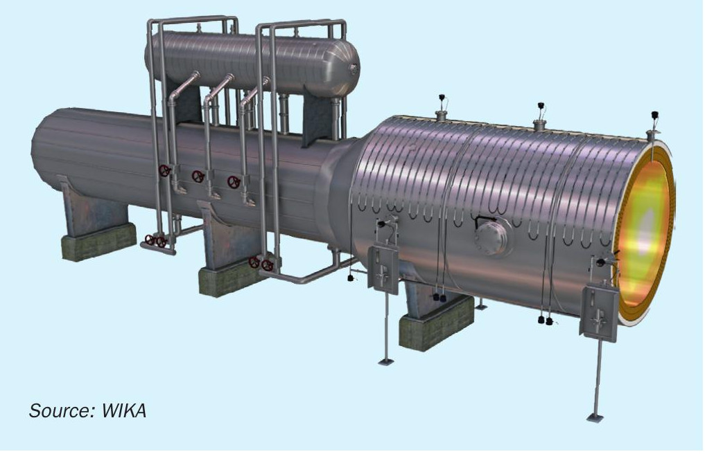
No real answer is clearly defined, but the problem really is. WIKA has acquired a very special technology where it can provide much better detection of hot spots at a reasonable cost. The heart of the system is a special sheath that in many ways resembles a thermocouple. The big difference is that instead of sensing at the tip, the readout records the hottest point anywhere along the sheath. This technology has been successfully running, monitoring a Claus unit for over 12 years at a major refinery in Italy. The refractory detection system (RDS) is run along the outside of the Claus thermal reactor along seams in the refractory (Fig. 1). This provides the best chance of seeing the temperature rising as this would be the likeliest place of failure.
The readings
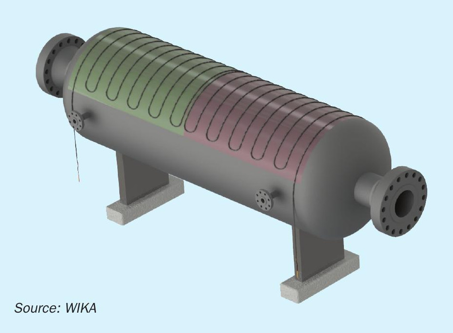
The system is installed on a Claus reactor by first dividing it into zones that will be monitored by the detection system. There can be anywhere from one to six zones in most Claus units (Fig. 2 shows a reactor with two zones). It all depends on the licensor or operator and what makes them comfortable. The readout from each zone will be like a type K thermocouple, but it is only the hottest area in a zone. It won’t pinpoint where in the zone the hotspot is, but you will know that there is one and then appropriate actions can take place.
Limitations
A couple of points should be noted:
- This is not a thermocouple. Modern transmitters have self-diagnostics built in and the readings below 120°C are not reliable. WIKA can prove the system is working at installation, but the unit will have to be started without a stable reading. WIKA can offer older transmitters that read to below 0°C, but careful consideration would need to be made in the evaluation process.
- Above 400°C, the readings again will lose their reliability, but they have done their job. No damage to the system will occur until getting to 900°C.
Installation
The refractory detection system is installed by trained field crew. Nelson studs are applied to the reactor and the system is held down by galvanised steel channels that are attached to the Nelson studs. This system will ensure that good contact is made between the RDS and the shell of the reactor. A six-zone unit, on a larger Claus reactor, took a three-man crew five to six days to completely install.
Customer feedback
The Italian refiner that has had this system for the last 12 years agreed to answer a few of WIKA’s questions. During this session he reported that he knew of no other system that could give him the coverage and protection that he was looking for. He really liked the reliability of the system. He had four zones and he lost a couple of zones over the years because of contractors cutting it, but it has still been very reliable. WIKA enquired if the system had ever alarmed over the 12 years and he reported that it had twice. In neither case did the hotspot get to the point that he had to shut down, but during the next routine maintenance they were able to see that in the zones where the alarm occurred, they did indeed have some refractory problems.
Temperature measurement of the Claus thermal reactor
Temperature measurement inside the Claus thermal reactor is something that is not well understood by many instrument engineers.
Most units operate with a pyrometer and two thermocouples. Several myths that many refineries follow are:
- The temperature from the thermocouple is only for the start-up process, it is sacrificial. The problem is that the process engineers then come back asking if the pyrometers are reading correctly. One major analyser representative reported that it was common that they know from the analysers the temperature is off and the refinery can only report that this is what they see.
- The purge is only for safety reasons, it is to make sure that if the ceramic breaks there is no risk of leaks. The purge is there for a totally different reason!
Why purge?
The operating range of a Claus thermal reactor is typically 1,300°C or higher. A type K thermocouple that is typically used in plants can’t operate at this elevated temperature, so Type S, R or B thermocouples are used. These are expensive platinum and rhodium thermocouples that work well at these temperatures but are very susceptible to hydrogen migration. As illustrated, the purpose of the purge is to take the hydrogen away.
Capex and opex of a purge
In a new project, purging is not something that comes without cost. Engineering is required to get the purge to the thermocouple, lines need to be installed, and then there is the cost of a purge panel. All these costs really do add up.
From an opex point of view, the purge is a maintenance problem. If the purge is too high, then the thermocouple will read low. If the purge is too low, then you lose the thermocouple prematurely. API states that daily inspection of the purge should be performed.
Some history
In 2015, WIKA acquired a technology that is used in gasifiers globally. Some of the patents go back to the early 2000s. Like a Claus unit, the gasifier is a high hydrogen and high temperature unit, but it is also high pressure unlike a Claus unit. This technology was applied to several Claus reactors, and one is known to be running successfully for ten years and another was replaced after nine years. In 2020, a redesign was done to optimise this technology for the Claus application.
How it works
The heart of the system is a mono crystal sapphire. This is a sapphire that is grown, so it has no real crystalline structure. This allows it to slow down hydrogen migration. The same technology of the sapphire and the acquired understanding of how to seal it were used in the new Calitum (Fig. 3).
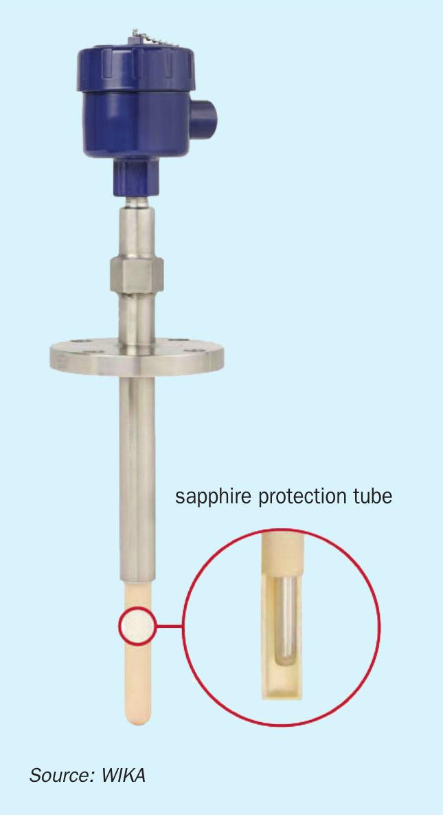
The Calitum
The Calitum is designed to give secondary containment which is pressure tested at 100 bar to ensure that no leakage from the process can occur if the primary containment or ceramic is broken. One benefit is that even if the ceramic is lost due to refractory movement, the unit will continue to read unless the nanocrystal sapphire is lost.
The Calitum can easily replace existing purged units and the life and reliability of Calitum can also bring profit to those currently operating without a purge.