Sulphur 394 May-Jun 2021
31 May 2021
SRU revamping for emissions compliance and capacity increase
SRU REVAMPING
SRU revamping for emissions compliance and capacity increase
With the sulphur content of crude oil and natural gas on the increase and with the ever-tightening sulphur content in fuels, refiners and gas processors will require additional sulphur recovery capacity. At the same time, environmental regulatory agencies of many countries continue to promulgate more stringent standards for sulphur emissions from oil, gas and chemical processing facilities. Rameshni & Associates Technology and Engineering discusses options for compliance with new regulations on emissions regarding IMO 2020 compliance and report on the results and evaluation of three case studies. Worley Comprimo reports on the revamp of a sulphur complex built in the late 1980s at a refinery in East Asia with the aim to increase the capacity, improve the availability and reliability and make the unit environmental compliant.
RAMESHNI & ASSOCIATES TECHNOLOGY AND ENGINEERING (RATE USA)
IMO 2020 compliance and SRU revamping
New regulations, such as IMO 2020, mandate a maximum sulphur content of 0.5% in marine fuels globally. The driver of this change is the need to reduce the air pollution created in the shipping industry by reducing the sulphur content of the fuels that ships use.
This will bring marine air pollution control in line with power plants and refineries, where continuous emissions monitoring systems (CEMS) monitoring NOx and SO2 emissions have been used for decades.
The first option to reduce sulphur emissions from ship exhausts is to burn fuel with a low sulphur content. This solution mirrors the land-based transportation sector where low sulphur petrol and diesel are the norm. Refineries are taking a variety of approaches to meet the changed demand for bunker fuels. Some will invest to increase the amount of low sulphur heavy fuel oil capacity and delayed-coker construction projects are underway in several locations.
The second option for marine emissions reduction is for ships to use conventional high sulphur fuel oil and an exhaust gas cleaning system (EGCS), similar to those used in land-based systems where power plants, for example, use scrubbers fed with lime to reduce sulphur emissions. With the demand for low sulphur fuels expected to increase, due to the IMO 2020 regulations, the price for these fuels is also likely to rise. Therefore, investment in an EGCS which enables the use of lower cost higher sulphur fuels may be highly attractive for shipping operators.
In general, EGCSs use either seawater in an open loop system or rely on internal recirculation of fresh water mixed with caustic soda or other alkaline chemicals as the scrubbing medium in a closed loop system. Some ports have expressed concerns about the discharge of open loop scrubber wastewater, so the closed loop versions have an important role to play, despite their additional operating cost. However, some scrubber processes can easily switch between the open or closed loop operation modes. This is particularly important in brackish waters such as river estuaries and means that the vessel can sail anywhere without over-dimensioning the scrubber system. Some scrubbers also incorporate a system for treating closed loop wash water known as bleed-off to comply with strict IMO requirements and can be discharged overboard.
A third option is that some refineries are adding a delayed coker to convert heavy, higher-sulphur residual oils into transportation fuels such as marine gas oil and diesel. The delayed coker follows other units at the site, such as the cogeneration unit and the diesel hydrotreater. Whatever the refinery does with regard to additional process units and configuration changes, one thing is for sure: increased sulphur removal will require increased quantities of hydrogen. Hydrogen reacts with sulphur to form hydrogen sulphide, which can either be burned in the refinery or converted to elemental sulphur for the chemicals sector. As a result, the existing sulphur recovery facilities require additional capacity to comply with the overall SO2 emission levels and environmental regulations.
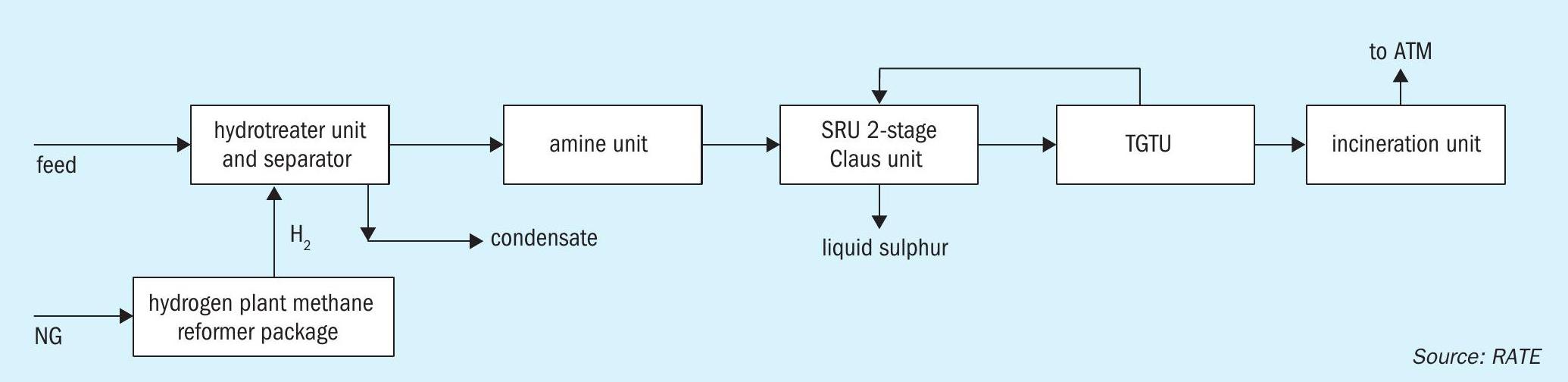
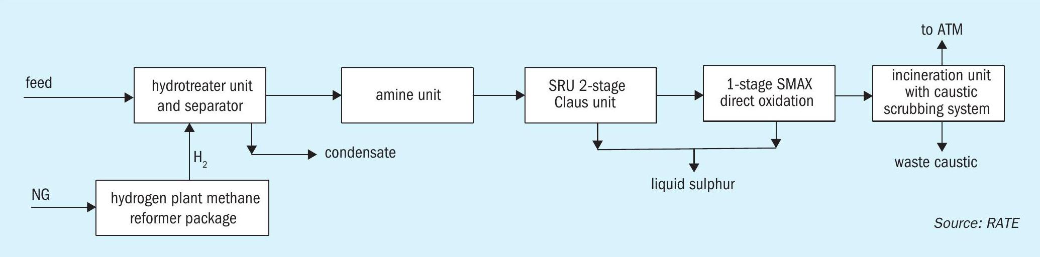
Fig. 1 represents a typical simplified refinery scheme showing the hydrotreater and the sulphur recovery units.
Crude oil-derived fuels contain aromatic compounds such as thiophene and its derivatives, which are forms of sulphur that are difficult to remove. Hydrodesulphurisation (HDS) is a catalytic chemical process used to remove sulphur from refined petroleum products. Typical catalysts used in HDS include sulphided Ni-Mo and Co-Mo active components supported on alumina. Traditional HDS processes create H2 S gas that needs to be scrubbed downstream.
Diesel hydrotreating (DHT) or catalytic hydrogen treating is mainly used to reduce undesirable species from straight-run diesel fraction by selectively reacting these species with hydrogen in a reactor at elevated temperatures and at moderate pressures.
RATE has studied three different projects related to this topic as described in the following sections.
Project 1
In project 1, a shipping terminal located in the USA, where environmental regulations are very tight, would like to reduce the sulphur content of the fuels it supplies to ships. Since the terminal does not have any processing units, to supply clean fuel would require high investment costs to install a large hydrotreater and a large sulphur block.
RATE’s proposal included the installation of a new hydrotreater, followed by an amine unit and the sulphur recovery unit plus all the utilities and required catalysts and chemicals. The new SRU/TGU would have a capacity of about 250 t/d. The required hydrotreater was a large unit. By the time the study was completed the capital cost for this grass root facility was significantly high. The conventional tail gas unit was therefore changed to produce ammonium thiosulphate solution, a product that can be sold and is profitable. This had the benefit of reducing the capital cost and providing a faster return on investment. The final decision has not yet been made.
Project 2
In project 2, an oil and gas operator trading refinery liquid products has a terminal and storage tank farm located in the Middle East. The facility has partial capability to process crude, and would like to supply clean fuel to its customers. Occasionally, liquid products are received that contain high levels of sulphur contamination, but nowadays many customers are looking for low sulphur products. The aim is to procure and install a desulphurisation unit with a processing capacity of 100,000 tonnes per month at the facility in order to reduce sulphur contamination from various refinery products such as diesel, fuel oil and gasoline, to meet the new regulations.
Diesel with a sulphur content of 10,000 ppm including mercaptans and fuel oil with 35,000 ppm sulphur content including mercaptans were evaluated. The product will meet less than 50 ppm of sulphur. The maximum amount of sulphur to be removed and processed is about 30 t/d.
Fig. 2 shows a block diagram of what was proposed in the study.
Since the sulphur recovery unit is relatively small, and in order to minimise the investment, RATE proposed SMAX direct oxidation technology plus a caustic scrubbing system after the incineration. The SO2 specification from the incinerator stack is less than 10 ppmv. The caustic will be neutralised as part of the design, so there will be no issues with a spent caustic waste stream.
In this study, the facility has the utilities required for the new units therefore, the total investment relative to the capacity is much lower than in project 1. The study is currently under review and consideration for the path moving forward.
As described in the introduction, in most cases the sulphur is removed from the fuel to meet environmental regulations, either by using a caustic scrubbing system at the port, or by using sea-water scrubbing when the ship is moving in the water.
Project 3
In project 3 a study was conducted for a refinery in Europe to convert heavy, higher-sulphur residual oils into transportation fuels such as marine gas oil and diesel. The facility has a hydrotreater and a sulphur recovery unit in operation, but depending on the refinery production capacity, the required size of these units will be different. The recovery of additional sulphur requires modifications to the existing units to comply with environmental regulations, including the hydrotreater, coker unit, amine unit, sulphur recovery and tail gas treating units.
Hydrotreater modifications
Starting with the hydrotreaters, the hydro-treater catalysts have been improved to take more sulphur compounds, sometimes hydrolysis reactors are added. In addition, as part of the revamp, additional sections can be added to the catalyst bed, or the configuration can be changed by adding integrated back-staged hydrocracking to the hydrotreating unit, or by using a two-stage hydrocracking configuration in the hydrotreating unit. A two-stage hydrocracking unit flow scheme with integration of hydroisomerisation catalyst to the hydro-treating unit will take care of the necessary modifications and are proposed by hydrotreater licensors.
Sulphur block evaluation and modifications
Where more H2S is to be processed in the amine unit, the amine solvent, the absorber and regeneration internals, and the reboiler duty should be evaluated. It may be necessary to use a higher amine concentration, change to a more selective amine solvent, upgrade the tower internals, or increase the reboiler duty to strip the additional H2 S and send it to the sulphur recovery unit.
Processing more H2S also requires additional capacity in the SRU. IMO 2020 mandates a maximum sulphur content of 0.5% for fuel in most cases this translates into additional sulphur capacity ranging from 20% to 70% which can be achieved by using low-level to medium-level oxygen enrichment. If even more capacity is required then high-level oxygen enrichment should be applied.
In terms of modifications, using low-level to medium-level of oxygen enrichment requires a control system on the oxygen line, and in most cases a new burner to handle the oxygen and upgrading of the refractory. The downstream equipment in the SRU should also be evaluated but in most cases no changes would be required.
SRU burner and reaction furnace
Low-level oxygen enrichment is accomplished by injecting pure oxygen or oxygen-rich air into the combustion air; i.e., oxygen is premixed with combustion air upstream of the burner. No burner modification is required in the existing SRU, other than providing the tie-in point for oxygen injection in the combustion air line. For medium-level or high-level oxygen enrichment with rich H2 S, the burner designed for air-only operation may not be able to withstand the higher combustion temperature. In any case, direct injection of oxygen through separate nozzles from combustion air is recommended; hence, special burners designed for direct oxygen injection should be installed.
The existing reaction furnace should be evaluated for low-level oxygen enirchment, but no changes are normally required. For medium- or high-level of oxygen enrichment, several factors should be considered.
If the sulphur plant to be modified has a feed gas with high H2 S content, a new reaction furnace is required as a first combustion chamber; the existing reaction furnace can be used as a second combustion chamber, provided that the existing reaction furnace is well maintained and the refractory lining is adequate. Oxygen enrichment has the following impacts on the burner and reaction furnace design:
- The existing refractory lining should be evaluated for the higher combustion temperature. In many cases, the refractory system will need to be upgraded to accommodate the higher operating temperature. The maximum operating temperature is limited by the refractory limits, about 2,700°F/1,480°C to 2,900°F/1,590°C (for short time excursions).
- If the burner needs to be replaced the size of the existing nozzle should be evaluated for the new burner location.
- If the reaction furnace contains a choke ring or checker wall, it should be evaluated for flame impingement with the new burner flame characteristics.
- A higher partial pressure of elemental sulphur, SO2 and H2 O vapour, leads to higher sulphur dew points.
- Producing more hydrogen, which is beneficial in tail gas treating as a reducing agent, can also be used as a fuel in the incinerator.
- Increase the efficiency of downstream Claus catalytic reactors.
- Better destruction of ammonia, HCN, heavy hydrocarbons and BTEX, or any contaminants, requires a higher combustion temperature.
- The gas volumetric is about the same, no changes in residence time.
- An oxygen line should be provided to the unit; a burner management system ESD system, and oxygen demand controls should be added or modified for oxygen supply. l Purging requirements will be different and should be considered.
- Pilot/ignition requirement should be evaluated.
- Acid gas piping pressure drop and instrumentation should be evaluated to maintain the pressure profile throughout the unit.
- The plot plan should be evaluated if the burner is replaced.
- The location for the flame scanners should be evaluated with the burner replacement for the replacement or relocation. RATE recommends IRIS S-550 type flame scanners for their robustness in sulphur plants and since they are not affected by pipe x-raying, heat and radiation on the site.
- The flow meters and control valves on the acid gas lines should be evaluated for a higher flow rate and turndown issues.
- The existing refractory should be evaluated for a higher combustion temperature in the reducing atmosphere. The principle of using double combustion for processing H2 S-rich acid gas is that 90% alumina refractory with silica, in a reducing atmosphere, has a maximum temperature limitation, and using 94% alumina refractory with magnesium is very sensitive to thermal shock in a reducing atmosphere and may not be very cost effective, but it will handle the higher combustion temperature. The melting point of 90% alumina with silica and 94% alumina with magnesium is about 3,400°F and 3,500°F respectively. However, the ferrules should be evaluated for this combination.
Waste heat boiler and steam drum
Hot gases leaving the reaction furnace are cooled in the waste heat boiler by generating steam. The existing waste heat boiler and steam drum should be evaluated, for low level of oxygen, no changes or concern is required. For a medium or high level of oxygen with rich H2S content, the existing waste heater could be used as a second pass waste heat boiler and a new waste heat boiler should be added as a first pass waste heat boiler.
For lean H2S acid gas and high-level oxygen enrichment, single combustion is adequate, therefore there is no need for an additional waste heat boiler, if the existing waste heat boiler is well designed and well maintained.
Oxygen enrichment has the following impacts on the waste heat boiler design:
- Higher operating temperature, resulting in higher heat duty, which requires more cooling.
- More sulphur vapour from the reaction furnace needs more heat for redistribution.
- Recombination of CO to COS, and H2 and S2 to H2S releases additional heat in front of several feet of boiler tubes, which is not predicated by some simulators. It increases the heat flux near the critical tube-to-tube sheet weld (maximum metal temperature), and inlet tube sheet refractory and ferrules (maximum heat flux in tubes) requiring mechanical attention.
- Improved heat transfer as a result of the higher radiant film coefficient.
- Steam drum size, downcomer/riser size and number, nozzle sizes, associated piping and instrumentation should all be evaluated.
- Relief capacity, BFW /steam rate will be increased.
- Mass velocities should not be exceeded or heat flux issues may arise, which may cause vapour blanketing of the tubes and high temperature in the tube and tube-sheet.
- The peak heat flux occurs at the outlet of the ceramic ferrules; therefore, the heat flux should be limited to a maximum 50,000 to 70,000 Btu/hr-ft2 to prevent eddying.
- The temperature of tube to tube-sheet weld should be limited and evaluated for the possibility of sulphidic corrosion of carbon steel.
Claus catalytic stages
The gas leaving the reheaters enters the Claus catalytic reactors. Oxygen enrichment has the following impact on the Claus catalytic stages:
- Larger temperature rises across the reactors and higher sulphur partial pressures. Since the Claus reaction is favoured by lower temperatures, having a higher sulphur partial pressure increases the extent of the Claus reaction.
- The volumetric flow will be the same, but there is more sulphur vapour present in the gas stream.
- The COS and CS2 hydrolysis will improve due to a higher temperature in the Claus reactors.
- If the conversion of the sulphur plant to oxygen enrichment is for the processing of lean or very lean H2 S acid gas, then the alumina catalyst in the first Claus reactor should be changed to titanium at the bottom, up to 50%, and alumina catalyst at the top to improve the hydrolysis of COS and CS2 .
- When converting the sulphur plant to high-level oxygen enrichment if the outlet piping of the first Claus reactor is carbon steel (CS), the material should be evaluated for changing to stainless steel (SS) or refractory piping due to the higher outlet temperature.
Reheaters and hot gas bypass reheat
The gas leaving the condensers enter the reheaters. The impact of oxygen enrichment on the reheaters having a higher temperature decreases the hot gas by-pass flow. However, the material and thermal stress in the existing piping should still be reviewed for revamp projects.
Claus sulphur condensers
The gas leaving the Claus reactors enters the sulphur condensers. High-level oxygen enrichment will have the following impact on the sulphur condensers:
- The sulphur condenser duties increase, because of the higher inlet temperature.
- Condensers will have a higher mass flux of lb/hr/ft2 as a result of higher duties and the target should be defined.
- The No. 1 and No. 2 sulphur condensers may require a higher heat duty. Replacement with a new condenser may sometimes be required. The impact on the other condensers is not significant.
- All relief valves should be re-rated for the new process conditions.
- All the utility lines such as BFW, steam and instrumentation should be evaluated for the new process conditions.
- All sulphur run downs should be evaluated because of the increased sulphur production.
TGU hydrogenation reactor, waste heat exchanger and contact condenser
The function of the hydrogenation reactor is to convert sulphur compounds (mostly SO2 ) to H2S and for the hydrolysis of COS and CS2 . The effect of oxygen enrichment is as follows:
- An increase in the concentration of sulphur compounds in the tail gas feed, results in a larger temperature rise across the hydrogenation reactor and higher duties in the waste heat exchangers and contact condenser.
- Since the SO2 concentration is higher in the tail gas feed, during conversion to H2 S in the reactor, the water vapour in the reactor is added to the water from the sulphur plant in the tail gas feed.
- There is a significant increase of the heat duty of the contact condenser – cooling loop includes water and air cooler.
- There is a significant increase in water circulation, pump capacity, and piping.
- The pH is noticeably lower due to a higher H2 S and CO2 partial pressure, and lower NH3 content. l The corrosion rate in the warmer sections of the contact condenser should be monitored more frequently.
- The tail gas volumetric flow rate is lower, even though it is required for cooling.
- If the sulphur plant conversion to oxygen enrichment is for the processing of lean or very lean H2 S acid gas, then the unit should be evaluated for a promoted CoMo catalyst for a lower COS outlet, because CO concentration is high and has a tendency to convert to COS.
- For conversion of the sulphur plant to high level of oxygen enrichment, if the outlet piping of the hydrogenation reactor is CS, the material should be evaluated for changing it from CS to SS or CS refractory piping to a higher temperature outlet.
TGU amine absorption and regeneration
The impact of the oxygen enrichment on the TGU amine absorption and regeneration is as follows:
- The feed to the TGU amine unit has a higher H2 S concentration and higher H2 S partial pressure.
- A higher amine circulation rate or higher amine concentration is required.
- More reboiler and overhead condenser duty is required.
- More cooling duty is required in the lean amine circulation loop.
- Piping and instrumentation should be evaluated case-by-case, especially for rich amine piping in terms of velocity, pressure drop, and higher flashing in the rich solution.
- The capacity of relief valve should be evaluated.
- The flow rate of acid gas from the amine regeneration reflux drum to the SRU is higher; therefore, the reflux drum size, instrumentation, velocity and pressure drop should be checked.
- The rich solvent will have a higher loading; therefore, critical equipment such as lean/rich exchanger should be evaluated for corrosion and erosion.
Incineration
Oxygen enrichment will have the following impact on the incineration system:
- Reduction of the volumetric flow from the amine absorber to the incineration.
- Increased H2 concentration and lower N2 concentration, which reduces the fuel gas demand.
- Increased the SO2 and water concentration in the stack.
- If the unit is equipped with a degassing unit, the H2 S content of the liquid sulphur will be increased and more H2 S will be routed to the incineration.
- The stack emission for sulphur species should be evaluated to meet environmental regulations.
Liquid sulphur handling/granulation
Oxygen enrichment will have the following impact on the liquid sulphur handling and granulation section:
- Increased sulphur production.
- Rundown piping and sulphur seal pots may require larger size or the existing to be replaced for an additional sulphur production.
- As a result of the higher sulphur production, the sulphur pit residence is reduced. The existing sulphur pit should be evaluated and may require a new sulphur pit, which will require some additional piping.
- The H2 S content of the liquid sulphur will be increased and more H2 S will be routed to the incineration.
- Sulphur pumps require a higher capacity and higher discharge head.
- If the unit is equipped with a degassing unit, the capacity of the degassing unit should be evaluated for the additional sulphur capacity.
- If the unit is equipped with a sulphur granulation unit, the capacity of the solidification and bagging facilities should be evaluated for the additional sulphur production.
Controllability
Over the past 20 to 30 years RATE has improved the controllability of its units by incorporating the following primary changes to the controls of sulphur recovery units:
- Use of distributed control systems for controlling the combustion air and acid gas feeds (and other control functions) to the sulphur recovery unit.
- Use of calculation algorithms to calculate actual air or oxygen demands to process the acid gases in the sulphur recovery unit (including capability of adjusting air demands for compositional changes in acid gases).
- Use of calculation algorithms to regulate the flows of sour water stripper gas and amine to front and rear chambers of the reaction furnace to provide optimal operating temperatures in the reaction furnace to thermally decompose ammonia in the first chamber by splitting the acid gases.
- Use of “smart” type flow transmitters with pressure and temperature compensation to provide more accurate flow rates with automatic conversion to mass flow rates and also to provide greater turndown capability – turndown of 6 or 7 to 1.
- Use of improved H2 S/SO2 analysers for more reliable trim air controls.
- Use of venturi type flow meters in acid gas and air streams to provide greater accuracy at turndown rates.
- Use of three element boiler feed water controls for waste heat boiler controls.
- Use of both special thermocouple designs and optical pyrometers for the reaction furnace
- Use of the latest flame scanner technologies for reaction furnace flame detection.
- Adaptive gain control on the tail gas analyser trim control
- Muti-variable control for the sulphur plant.
- Advanced control technology.
Oxygen piping criteria
Most oxygen piping systems are made of steel or stainless steel materials and operate at pressures of 1,000 psig/69 barg or less and temperatures below 200°F/93°C. Stainless steel has the maximum allowable velocity in the pipe. The oxygen valves are chosen from Monel or Inconel, which are permitted at the high velocity and pressures up to 1,000 psig. Oxygen piping systems should be kept as simple as possible, with the smallest possible number of valves, fitting, branches and nozzles. All process control valves should be in throttling service. Only globe valves or needle valves should be used for throttling.
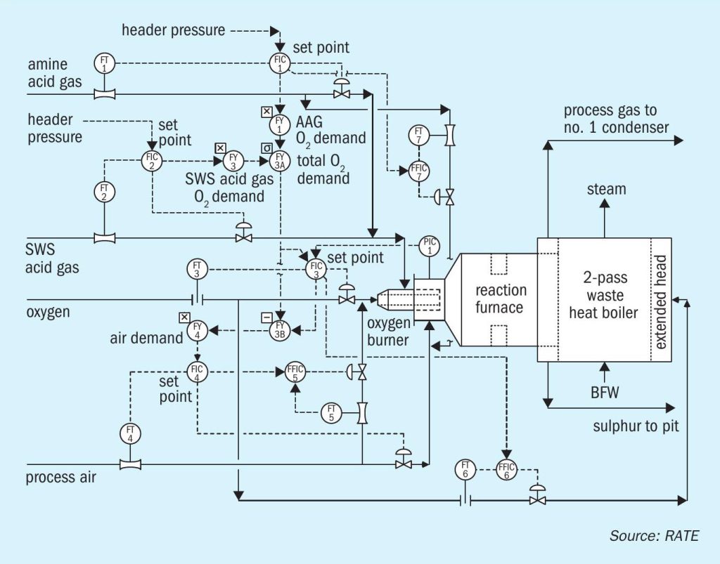
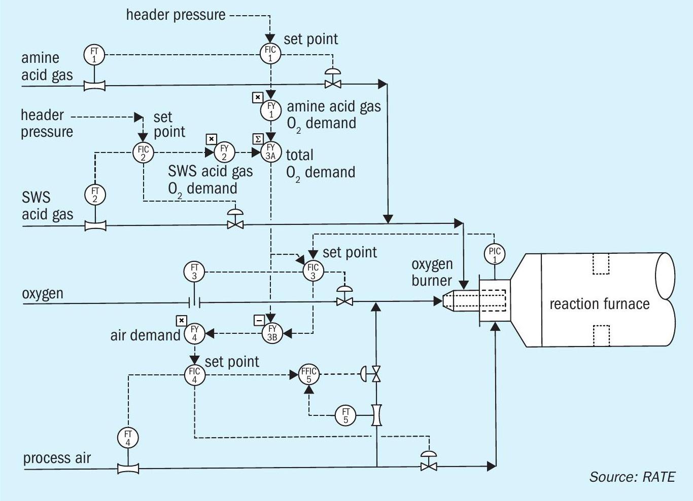
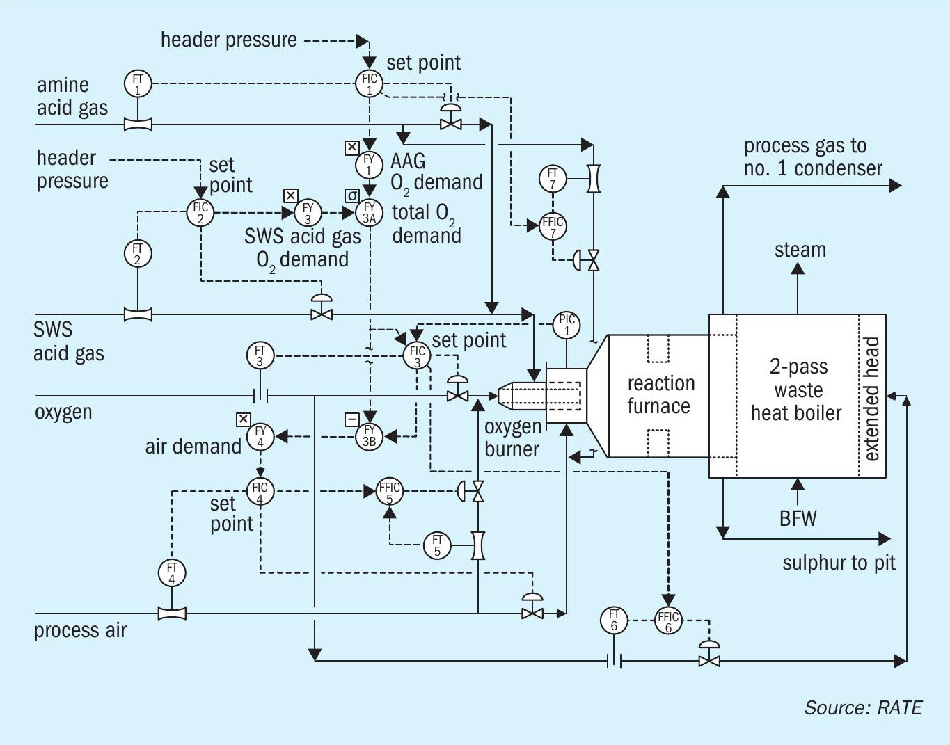
Figs 3 and 4 represent the control system and equipment modifications for using low to medium-level and high-level of oxygen enrichment respectively.
SO2 emission reduction
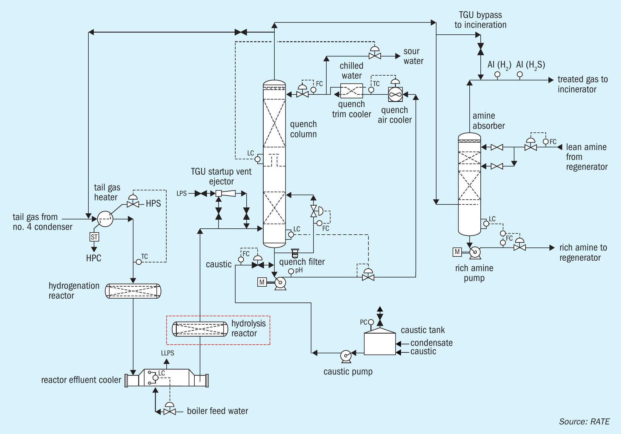
The final step to consider when considering an increase of H2 S to the sulphur recovery unit or a capacity expansion is how to maintain or lower the SO2 emission. Options include changing the amine solvent in the tail gas unit, routing the pit vent to the reaction furnace and using a patented tail gas scheme where the hydrolysis reactor is added after the hydrogenation reactor since the COS and CS2 are not fully hydrolysed in the hydrogenation reactor and operating data shows that at least 30-50 ppmv of SO2 comes from COS, CS2 , and sulphur species. The hydrolysis reactor can have a common shell with the hydrogenation reactor (see Fig. 5).
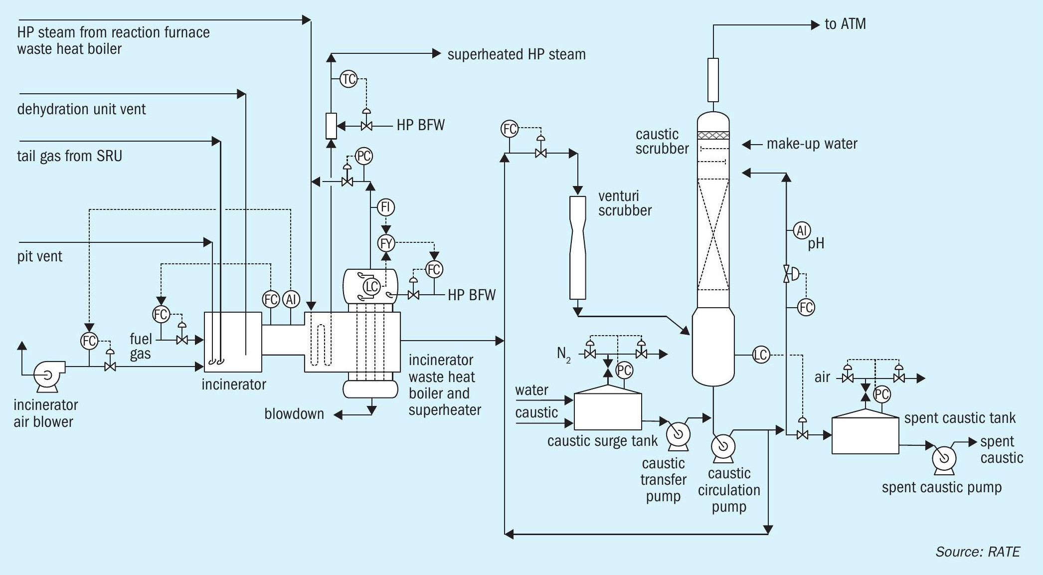
Another option is to have tail gas incineration with a caustic scrubber system, which would eliminate changing the solvent and maybe other modifications. The caustic scrubber is added after the incinerator and before the stack as shown in Fig. 6).
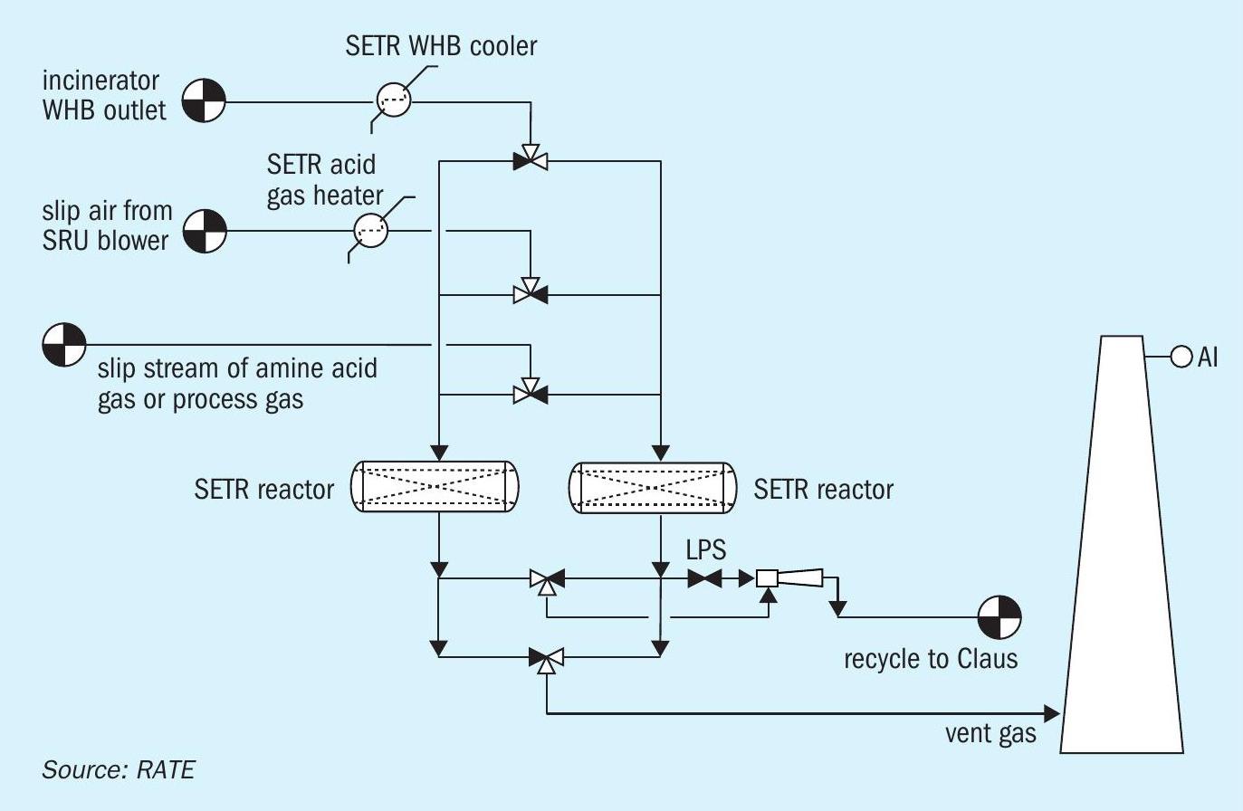
Finally, SETR is a new US Patent technology by RATE for application where low emissions of SO2 are required. SETR is an SO2 adsorption-based Claus tail gas process with fixed bed reactors that are heated up and cooled down. SETR is located after the incinerator and before the stack as an alternative to caustic scrubbing systems. SETR can be added to any SRU such as SRU/TGU, SMAX, SMAXB, SuperClaus, EuroClaus, CBA, SuperSulf, or any other sub dew point processes. The advantages are no waste stream, no chemical requirements, and all the sulphur is recovered and recycled back to the Claus unit (Fig. 7).
Summary and conclusions
This article discusses the impacts on sulphur recovery as a result of implementing IMO 2020 compliance globally. The most important and obvious impacts are the new investments that need to be allocated, many of which are not cost effective and are too difficult to meet such regulations.
The most common practice used by the shipping industry for compliance is to use a caustic scrubbing system when at the port and to use sea-water scrubbing when away from the port and moving on the water.
If facilities like refineries are required to meet IMO 2020 fuel specifications, they may need to perform modifications to the hydrotreating and sulphur block. The extent of such modifications should be evaluated case by case, sometimes they operate under design capacity so they have enough capacity to take more sulphur out. Sometimes the original design are based on much heavier crude oil and over the years changed to less heavier crude and have the capacity to process more without any modifications.
WORLEY COMPRIMO
Revamp and capacity increase of a sulphur complex in East Asia
Worley Comprimo was approached a couple of years ago by a refinery in East Asia to revamp an existing sulphur complex that was built in the late 1980s with the aim to increase the capacity, improve the availability and reliability and make the unit environmentally compliant. The sulphur complex processed the rich solvent and sour water from an upstream system that was debottlenecked to increase production. The challenges that were faced are described in this article.
The sulphur complex consisted of two amine regenerators, one SWS, two identical SRU trains and two identical TGT trains with a catalytic incinerator. For the whole complex, the target was to increase the capacity by 25% (amine circulation, sour water processing, amine acid gas and sour water acid gas).
Amine regenerator no. 1 was a two-stage regenerator that produced lean solvent for the refinery absorbers and superlean solvent for the TGT absorbers. With the superlean solvent, an H2 S slip of less than 10 ppmv could be achieved in the TGT absorbers. A new flash drum was installed to provide adequate solvent degassing/de-oiling to minimise hydrocarbons in the amine acid gas. In the regenerator overhead new trim coolers were installed to cater for the increased condensing duty. For these trim coolers welded plate-and-frame exchangers were specified to minimise plot space requirements. Also, the reboilers and the superlean trim coolers were replaced with welded plate exchangers for minimal footprint and maximum duty, whereas for the lean solvent cooling an additional welded plate trim cooler had to be installed. The internals of the column needed minor rework to handle the increased reboiler steam (new inlet device), but the trays were generously designed originally and could be maintained.
Amine regenerator no. 2 had been generously designed both from an equipment perspective and from a layout perspective, so here the revamp was limited to replacing the reboiler (kettle for kettle) with a larger heat transfer surface. The overhead condenser was extended with an additional welded plate trim cooler, as was the lean solvent cooler.
Although it was originally planned to design a new sour water stripper, this stripper was not built for budget reasons. By sharing the sour water load with other strippers in the refinery, the required sour water capacity could be managed without installing an additional sour water stripper.
For the Claus section of the sulphur recovery units, low level oxygen was introduced. Low level oxygen enrichment has the benefit that the hydraulic load in the catalytic stages stays more or less constant, since less inert nitrogen is passing through the unit. Typically, the capacity of the unit can be raised by up to 35%. However, with oxygen enrichment substantially more heat is released in the thermal reactor, which leads to temperatures that are too high in the outlet from the thermal stage process gas cooler/condenser. The complete thermal stage, including the knock-out drums, was therefore replaced with a new, state-of-the-art thermal stage, including air preheating, which was required to enable recycling the vent air from the new pressurised degassing system in the combustion airline. (Worley Comprimo favours recycling the vent air to the combustion airline over injecting the vent air into the thermal reactor to avoid improper mixing and potential oxygen slip). The control system of the thermal reactor was upgraded to an advanced burner control (ABC) system. The ABC is organised in such a way that the back pressure of the unit is always at a constant high level when in enrichment mode, thus maximising the hydraulic load of the plant and minimising the oxygen consumption. No changes were made to the three catalytic Claus stages.
The sulphur run-down to the sulphur pit was maintained, but the in-pit degassing was eliminated as it was insufficient to meet the typical industry accepted degassing value of 10 ppmw H2 S, making the sulphur pit a storage pit. From this pit, the undegassed sulphur was pumped to an external degassing drum which operates at elevated pressure, such that the vent air from the drum can be routed to the thermal reactor instead of to the catalytic oxidiser. The vapour space of the pit was still vented with an ejector to the new thermal oxidiser, but since the degassing no longer takes place in the pit the vent air contains little to no sulphur species, such that the flue gas spec of 50 ppmv SO2 can still be met.
The TGT and the catalytic oxidiser were highly integrated with a gas/gas heat exchanger heating the tail gas to the TGT reactor against the flue gas from the catalytic oxidiser. The TGT reactor was loaded with conventional catalyst which required an inlet temperature of 280°C. By changing out the catalyst with a best-in-class low temperature catalyst, the inlet temperature could be reduced to 210-220°C, which opened up the possibility to replace the gas/gas exchanger with a 40 bar steam heater.
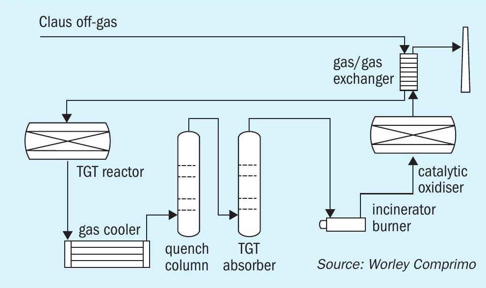
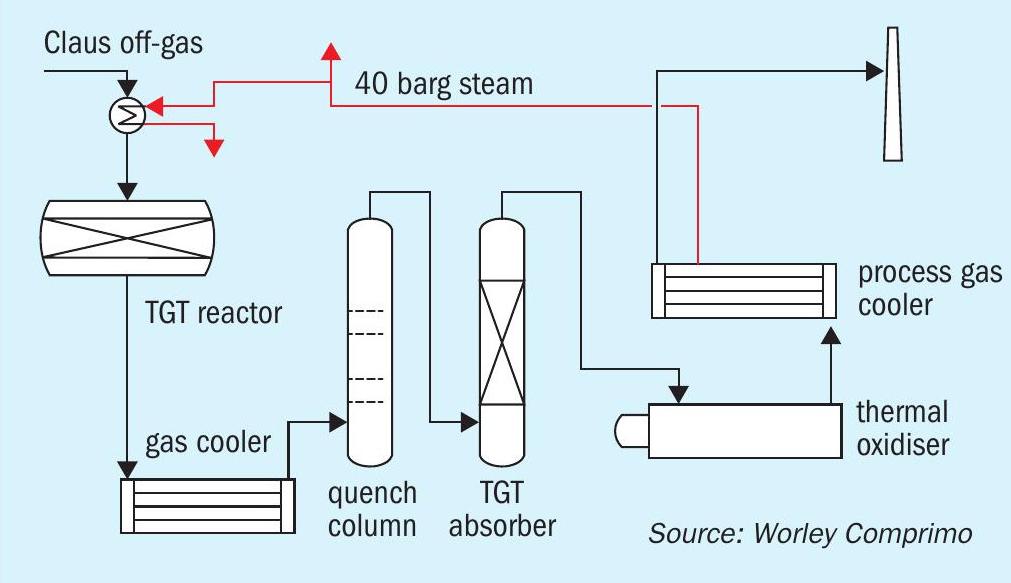
Fig. 1 shows the original setup with a catalytic oxidiser and gas/ gas exchanger and Fig. 2 shows the new arrangement with a steam heater/thermal oxidiser with a 40 bar process gas cooler.
The original TGT design had a blower for start-up and low throughput operation which had proved to be unreliable. The blower line-up was retained, however, an ejector was installed in the outlet of the TGT process gas cooler outlet that could fulfil the same service with a very high reliability. With the installation of the ejector, the blower effectively has become idle.
Since the process gas from an oxygen enriched Claus unit contains less inerts and more water vapour, which needs to be condensed before the gas can be routed to the absorber, the duty on the quench water cooler increased substantially, and hence the shell and tube quench water cooler was replaced with a welded plate and frame exchanger which can do the larger duty on a smaller footprint.
To minimise the pressure drop over the complete Claus and TGT unit and to improve the absorption efficiency (which is required due to the fact that with oxygen enrichment the H2 S concentration to the absorber increases), the trays in the TGT absorber were replaced with structured packing. By doing so the oxygen demand of the thermal reactor was minimised, as well as the slip of H2 S from the TGT absorber, allowing the requested limit of 50 ppmv SO2 in the flue gas to the stack to be met.
Since the catalytic oxidiser was no longer environmental compliant due to the high CO slip it was replaced with a thermal oxidiser followed by a process gas cooler generating 40 bar steam. This steam is partly used in the TGT reheater, and the excess is routed to the refinery grid. Since the plot space that was freed up by removing the catalytic oxidiser was limited it was decided to build the process gas cooler on top of the thermal oxidiser.
After the basic engineering was finished by Worley Comprimo, the detailed engineering was done by a local contractor. All the above-described changes were implemented during a 20 week shutdown, after which the unit was smoothly started up again.
During the test run that was done after stabilising the unit all emissions and product specifications were met, i.e. SO2 in the flue gas was less than 50 ppmv, NOx was less than 50 ppmv and CO was even less than 20 ppmv. The produced sulphur contained less than 10 ppmwt H2 S.
This revamp has shown that welded plate and frame exchangers have very good performance in amine systems, since they combine a high duty with a small footprint, making them ideal for replacing existing shell-and-tube exchangers.
The increased capacity can be easily handled with low level oxygen enrichment, however, the increased thermal duty makes it typically necessary to at least change out the process gas cooler.
The increased capacity can be easily handled in the TGT, and only some additional cooling in the quench circuit is required to handle the additional condensing of process water from the tail gas.
The replacement of the catalytic oxidiser with a thermal oxidiser with heat recovery opened up the opportunity to simplify the operation of the TGT, while at the same time making the complex environmentally compliant.