Nitrogen+Syngas 373 Sept-Oct 2021

30 September 2021
2021 AIChE Ammonia Safety Symposium
CONFERENCE REPORT
2021 AIChE Ammonia Safety Symposium
Venkat Pattabathula, a member of the AIChE Ammonia Safety Committee, reports on the American Institute of Chemical Engineers’ Safety in Ammonia Plants and Related Facilities Symposium, held virtually on 30 August to 2 September 2021.

The Ammonia Safety Committee is dedicated to improving the safety of plants that manufacture ammonia and related chemicals, such as urea, nitric acid, ammonium nitrate, and methanol. Attendees to the symposium, who include plant safety personnel, plant managers, and process engineers representing a spectrum of nitrogen fertilizer based industries, amongst others, share technological advances and discuss strategies for improving plant safety, maintenance, and management. This year’s virtual event – the first in the organisation’s history – included about 250 engineers from more than 30 countries and 75 companies.
Clean ammonia
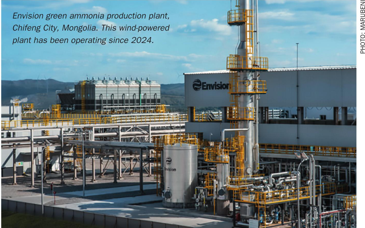
This year’s keynote speech; ‘Clean ammonia: scaling up for new opportunities’, was presented by Trevor Brown, executive director of the Ammonia Energy Association (AEA), who advocated for ammonia’s responsible use in a sustainable energy economy. According to the International Renewable Energy Agency (IRENA), by 2050, about 70 million tonnes of current ammonia capacity will either be shut down or have been converted from fossil to renewable inputs. But about 500 million t/a ammonia capacity could be developed using available renewable energy sources. The prediction is that demand for clean ammonia will grow in industries such as fertilizer, maritime fuel, as a hydrogen carrier and as a fuel for electric power generation.
A number of low carbon ammonia projects are already under way. Already announced low carbon ammonia revamp projects include:
- CF Industries – 600,000 t/a including at Billingham, UK;
- OCI Beaumont – 365,000 t/a;
- ADNOC, Ruwais: 1 million t/a;
- PAU Sulawesi: 660,000 t/a;
- SAFCO, Al-Jubail: 1 million t/a; and
- Nutrien, North America: 450,000 t/a.
In addition to these, there are green ammonia electrolysis-based pilot projects at: Yara Pilbara (Engie); Fertiberia; Yara Sluisil; Yara Porsgrunn: and CF Donaldsonville, and new mega ammonia renewable projects announced for:
- Asian Renewable Energy Hub (Australia): 9.9 million t/a, 16 GW wind+solar.
- Svevind (Kazakhstan): 15 million t/a, 45 GW wind+solar.
- Aman (Mauritania): <20 million tonnes, 30 GW wind+solar.
- Al Wusa (Oman): <10 million tonnes, 15 GW wind+solar.
- Western Green Energy Hub (Australia): 20 million tonnes 50 GW wind+solar.
- Grand Inga Dam (DRC): >20 million tonnes, 40 GW hydroelectric.
Safety incidents
This year’s key safety-related papers were:
Failure of a hot walled ammonia synthesis converter
The ammonia plant was shut down for a turnaround, and as part of the risk-based inspection (RBI) programme, an inspection was performed in and around the shell and nozzle welds of the second synloop converter. Indications of hydrogen assisted cracking (HAC) were found between the man-way nozzle top head and bottom inlet/ outlet nozzle. The root cause investigation concluded that the cracking phenomenon resulted from a combination of nitriding at the inner surface and hydrogen-induced embrittlement. The nitride inner layer was prone to cracking when taking the equipment in and out of service and acted as a crack initiation point. Moreover, the hydrogen charged material exhibited a lower threshold stress resistance factor and a higher crack propagation rate with respect to uncharged material. The usage of a high strength material (3Cr type compared to 2.25Cr) also increased the stress level at the cracked areas.
The following preventive actions have been planned: adjustment of inspection planning for all converters, ensuring that time of flight diffraction (TOFD) and phased array ultrasonic testing (PAUT) are performed to find cracks in all orientations; and the establishment of minimum pressurising temperature (MPT) curves for all converters and adjustment of operating procedures if required.
Failure of ammonia synthesis converter internals
A complete failure occurred on the inlet and outlet expansion joints for the first bed interchanger in an ammonia synthesis converter. The direct cause of the failure was the overpressure of the converter during start-up. To prevent a reoccurrence, the following recommendations were made:
- Minimum stop of 15% on one of the quench valves.
- Installation of DCS indications with alarms for the differential pressure between the inlet and outlet of Interchanger #1.
- Installation of an automated converter pressurisation scheme to provide a controlled and well measured system by which the converter is pressurised during a startup.
- To properly sample for moisture prior to introducing gas into the converter, the start-up procedure will be altered to ensure sampling is performed on the discharge of the synthesis gas compressor.
Failure of a high-pressure steam superheater header
The outlet header of a high-pressure steam superheater located in the convection section of a primary reformer failed catastrophically, leading to significant damage to surrounding equipment and extended plant downtime. The failure occurred despite using materials in compliance with the ASME code. The failure of the HP steam superheater was a major event that resulted in an unplanned and extended plant outage and could have been much more serious. Stress relaxation cracking of austenitic alloys has been recognised for some time. The use of these alloys appears to have become more common since the turn of the century due to the relative reduction in price compared to ferritic materials of similar strength. This has led to an increase in the number of reported stress relaxation failures. The ASME code has recognised this problem for alloy 800H pressure vessels built to ASME Div. VIII, and introduced a post-weld heat treatment for design temperatures above 1000°F (538°C). Such heat treatments are not required for other austenitic alloys unless cold work strain and design temperature limits are exceeded.
The experience from this event suggests it is inadequate to avoid in-service stress relaxation limits. It is considered that requirements for post-weld heat treatments of new builds using austenitic alloys at elevated temperatures should be considered.
For existing applications, the need for inspection to ensure freedom from cracking is important. The plant had a risk-based inspection system in place. However, stress relaxation cracking had not been identified as a possible damage mechanism due in part to compliance with the ASME code and the relatively low operating temperature. This experience has raised the awareness of stress relaxation cracking as a potential damage mechanism, and inspection tests have been introduced to monitor susceptible plant equipment. The lessons learned from this incident have resulted in significant changes to the risk management of stainless-steel components operating at elevated temperatures in all Methanex facilities.
This has introduced additional problems related to non-destructive inspection. The sound portion of the seam weld in the HP superheater outlet header and the equivalent weld in the inlet header were inspected for damage using ultrasonic methods. These inspections reported cracking was also occurring in these welds. Subsequent investigation found minimal damage. It is thought that beam bending of the ultrasonic wave due to microstructural variations was responsible for the false interpretation that weld root cracking had occurred. These false-positive results have led to ongoing investigations into ultrasonic testing procedures to improve the sensitivity and reliability of these methods.
Failure and field repair of urea reactor shell rupture
The outer shell of a multi-layered urea reactor ruptured while the plant was in operation. The plant made an emergency shutdown, samples were collected, and an investigation was carried out to establish the root cause of the failure.
Urea reactors are usually vertical pressure vessels with either a mono-wall, multilayer, or multi-wall construction. Because of the corrosive nature of the medium, the interior surface of the vessel is lined with corrosion-resistant materials. The inside surface of the reactor showed signs of corrosion on the long liner seam, circumferential joints, and buttering welds (old cleat removal area). During the air test, weep holes were blocked due to the solidification of carbamate in the leak path. The air test was performed after the weep holes were cleared leakage in the long liner seam. Corrosion attack was observed on the dummy shell layer and first shell layer in the vicinity of the liner leakage.
Lessons learned:
- Approved contractors should perform liner fabrication and welding.
- Liner welding should be performed using fixtures to restrict the lifting of the liner during welding and creating excessive air gaps.
- The optimum weld sequence should be developed to reduce the liner shrinkage during installation.
- The weld process parameters and filler wire selection should be optimised to restrict the heat input during pass partition plate welds.
- All attachments on the liners shoud be full penetration welds.
- Vent holes should be inspected and verified as open following the erection of lined vessels and also during each turnaround.
- As the process licensor specifies, periodic quality checks for the weep tube leak detection system are mandatory.
Explosion inside HP urea reactor
A urea plant was operating for decades when during a restart, an abnormality was observed in the form of a rumbling sound not heard before. No actions were taken at that time, and the reactor was operated as normal with barely any difference in operational parameters. Upon opening of the reactor during a planned turnaround, however, it was observed that all of the trays were displaced from their supports and deposited in the bottom of the reactor. Most of the trays were heavily deformed.
A root cause analysis found that an explosion must have occurred between the 3rd and 4th tray during start-up with sufficient force to displace all the trays from their supports, depositing them in the bottom of the reactor. The analysis found that the most likely cause was the formation of a combustible mixture that exploded due to self-ignition or due to ignition caused by a static discharge. Before this occurrence, no scenarios were recognised which could lead to such an incident.
The scenario described only occurs when inerts get the chance to accumulate in combination with high hydrogen content in the carbon dioxide. To prevent the recurrence of this incident in the future, the following measures were planned:
- A hydrogen analyser has been installed in the carbon dioxide feed to the reactor.
- The start-up and shut down procedures have been adapted to prevent the accumulation of hydrogen.
- The vent valve will not be fully closed anymore during these periods to allow inerts to be vented to the downstream sections.
- All personnel will be instructed regarding the risks of inert accumulation in general, especially during start-up and shut down activities.
- All work instructions have been adapted to reflect the findings and to avoid this scenario from occurring again.
Corrosion under insulation
Corrosion under insulation (CUI), despite being very well known, is responsible for significant maintenance costs in the process industry. There is no doubt that CUI threatens the safe operation of our installations, but with a change in organisational culture that drives continuous improvement using standard work protocols, CUI can certainly be controlled. For sites without an established CUI inspection program, a significant initial effort and capital will be required to develop and execute new inspection processes. This case clearly shows that this is an effort worth making.
Mitigations:
- The use of thermal insulation for services that required insulation just for personnel protection was stopped
- Improved practices around the preparation of metal surfaces prior to application of the coating and the selection of coating for new insulation applications and repairs.
- Use of piping for rigging and support during maintenance activities was abandoned to prevent damage to insulation
- Insulation craftsmanship and caulking methods were reviewed
- The operations team will incorporate annual insulation surveys to identify insulation deficiencies and prevent water ingress by repairing insulation damages.
- Repositioning of supports and brackets where insulation is replaced and avoiding couplings under insulation lagging
- Begin use of organic coatings on carbon steel equipment and use of aluminium foil for protecting stainless steel
Round table
On the Symposium’s fourth and final day, a round table session was held, with topics which included an ammonia pump failure that led to two fatalities; changing a tank’s outlet manifold with a passing isolation valve; a safety park in Brunei; reforming furnace tube failure resulting in fire outside the box; 1.5 million years of Safurex operation; and incidents and near misses in ammonia plants.
Next year’s symposium will be in Chicago, from 12th-15th September 2022.


