Fertilizer International 509 Jul-Aug 2022
31 July 2022
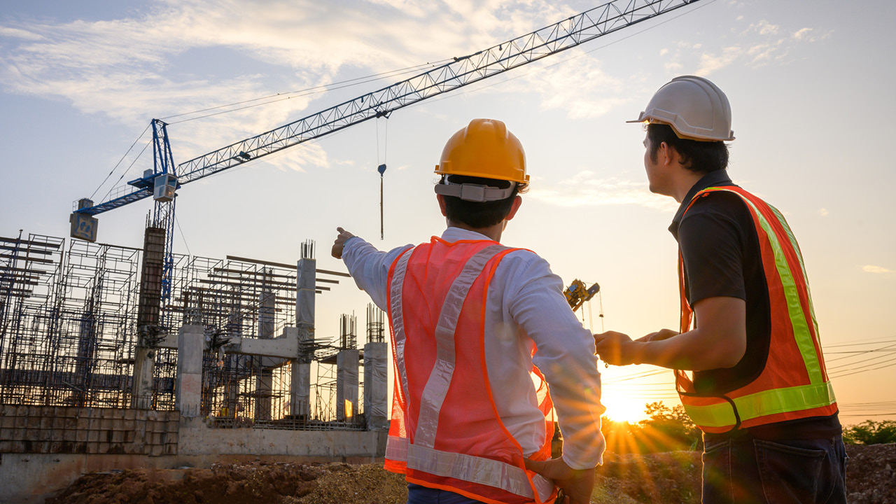
Fertilizer plant revamping: technology & projects
PRODUCTION TECHNOLOGY
Fertilizer plant revamping: technology & projects
The refurbishment and modernisation of fertilizer plants offers the opportunity to reduce operating costs, raise production capacity, improve energy efficiency and cut emissions.
CASALE
Recent revamp success stories
Fertilizer plant revamping is a longstanding and core area of expertise for Lugano-headquartered Casale. The Swiss company’s extensive revamp experience encompasses ammonia, urea, NPK and phosphate plants worldwide. This includes major interventions to improve the performance and replace obsolescent equipment at more than 200 ammonia plants globally.
Below, we highlight recent Casale revamp success stories from a track record stretching back decades.
Grey to green ammonia
In May this year, after completing hundreds of revamps that have increased production capacity and reduced emissions, Casale unveiled a ground breaking zero-emissions project to convert an existing ammonia plant from conventional (grey) to low-carbon (green) ammonia production.
Incitec Pivot Limited (IPL) asked Casale to deliver the technical know-how and the basic engineering design to convert its Gibson Island ammonia plant in Queensland, Australia, from natural gas feedstock to renewable hydrogen.
Under current proposals, IPL’s project partner Fortescue Future Industries (FFI) will construct an on-site water electrolysis unit at Gibson Island and develop and operate a hydrogen manufacturing plant, while IPL will continue to operate the site’s ammonia plant.
The proposed new water electrolysis unit at the site will have the capacity to produce up to 50,000 t/a of renewable hydrogen – and therefore completely replace Gibson Island’s current natural gas feedstock. This renewable hydrogen will then be converted into more than 300,000 t/a of green ammonia for the domestic Australian market and for export.
Gibson Island has the potential to become the first operating ammonia production plant in Australia to be converted to 100 percent emissions-free production. However, while the project is technically feasible, IPL and FFI are currently carrying out a front-end engineering design (FEED) study ahead of any final investment decision.
“We are grateful for the trust placed in us by our long-standing client IPL and proud to provide our technology and know-how to contribute to a greener future for Australia, accelerating the decarbonisation of the industry,” said Federico Zardi, Casale’s CEO. “Casale has always been a pioneer in implementing cutting-edge technologies into existing plants: this project can set the benchmark for all the ammonia plants in the world that have the ambition to turn green.”
New US ammonia plant revamp
Casale has six main revamping concepts for ammonia:
- Moderate capacity increases – a standard scheme for increasing plant capacity by up to 30 percent by making the maximum use of existing equipment and leaving the main process unchanged.
- Superevamp – a patented concept to increase plant capacity by up to 100 percent and deliver energy savings of more than 0.5Gcal/tNH3 .
- Saveng revamping for fixed natural gas allocation – this can reduce energy consumption at ammonia-urea complexes by 5.0 Gcal/t (urea) with an emphasis on plant integration and energy optimisation.
- Revamping for energy saving – this makes plants more competitive by increasing the efficiency of their most energy-consuming sections.
- Revamping to reduce emissions – a revamp designed to improve pollutant emissions and meet the most stringent environmental regulations.
- Revamping for production stabilisation – this revamp option enhances cooling capacity (without penalising energy consumption) to reduce the differences in production load between hot and cold seasons.
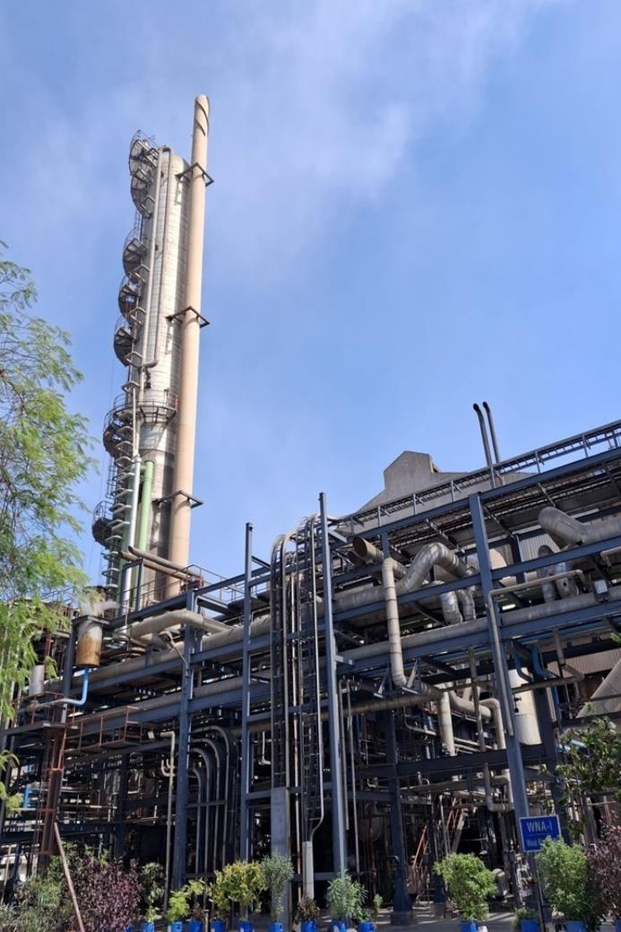
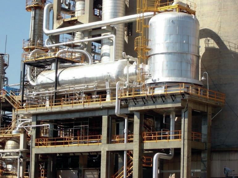
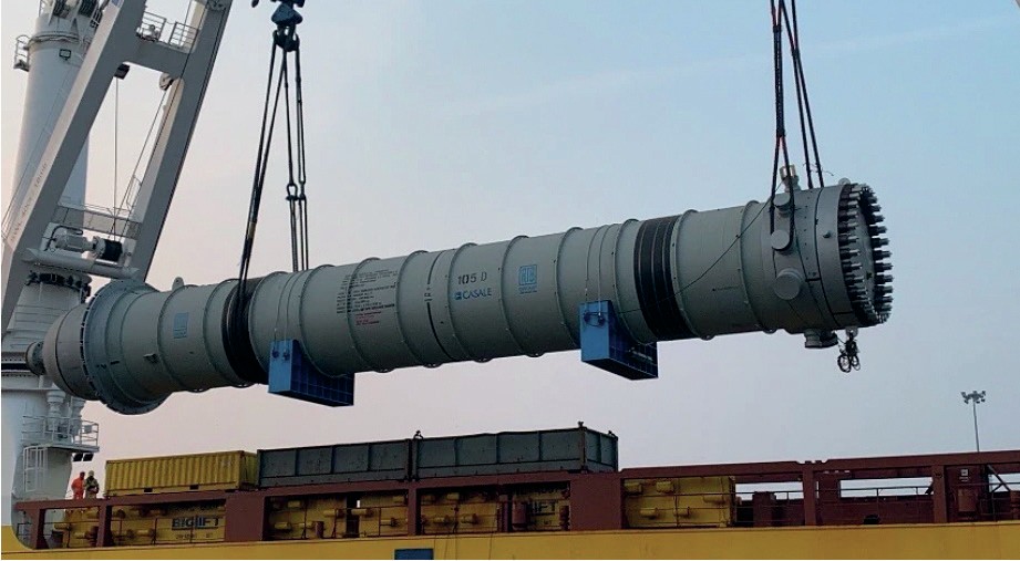
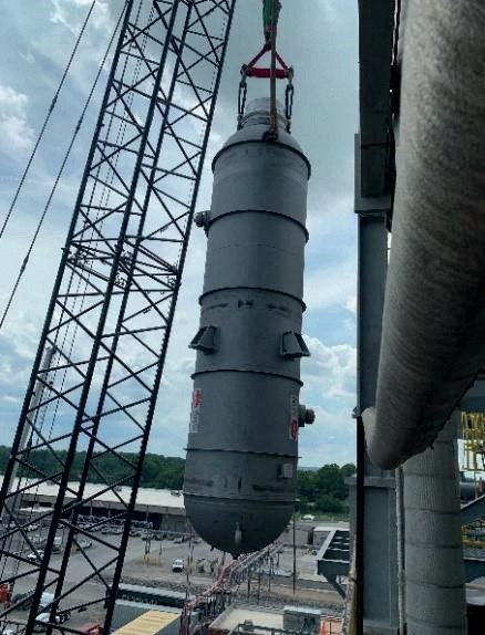
In November last year, Casale highlighted its revamping experience in North America with the thirteenth replacement of an ammonia converter pressure vessel in recent years. The company shipped a 400+ tonne reactor and a boiler feed water (BFW) preheater to the US to replace obsolete equipment (classic 105-D unit coupled to 123-C) at a MW Kellogg plant (see photo).
These replacement reactors incorporate innovative structural and technological features:
- Full-opening converter
- Single-wall converter
- Three-bed cartridge
- Cold-wall pressure vessel
- No-quench design.
This ensures they deliver tangible benefits to ammonia plant operators – including better accessibility to the internal parts of the reactor, greater safety, higher performance, energy savings and lower emissions.
New HP stripper for Grupa Azoty urea plant
Casale delivered a new high pressure (HP) stripper to Grupa Azoty Pulawy in Poland in June 2021. This was supplied as part of the replacement and modernisation of the HP stripper in the synthesis section of the company’s Puławy Urea Plant 2.
The stripper replacement follows the revamping of the Puławy urea plant in 2010, and the supply of other equipment and plant modifications since then. These have improved the plant’s performance and supported Grupa Azoty’s CO2 emissions reduction policy.
The stripper is made with Uremium 29 and was built with Casale technology and designed at the Villa & Bonaldi workshops, a specialised and experienced Italian manufacturer of HP shell and tube heat exchangers. Uremium 29 is recommended for the tubes of HP pressure equipment (as well as piping and fittings) as it increases reliability and operating life. This new alloy has very high resistance to carbamate-induced corrosion and was specifically developed by Tubacex, the world leading tubing manufacturer, in cooperation with Casale.
The latest delivery to Grupa Azoty means Casale has now supplied more than 35 HP strippers to date for both new and revamped urea plants. Their materials of construction range from super-austenitic to superduplex alloy (e.g., Uremium 29) to more exotic types such as titanium and zirconium.
A new high pressure stripper supplied by Casale to Yara’s Ferrara urea plant in Italy also successfully achieved its first full year of operation in March 2021. This was an important milestone as the stripper is among the first industrial references to use Uremium 29 in the construction of critical urea service parts.
“This stripper is a vital part of the urea plant and has come in the wake of the complete revamp that we undertook only a few years ago.” commented Federico Zardi, Casale’s CEO.
New high pressure boilers for Fertiberia
In June last year, Fertiberia awarded Casale a contract to supply three replacement high pressure process boilers (RG boilers). The new Casale-Schmidtsche Schack boilers will replace the existing boilers at Fertiberia’s ammonia plant at Palos, Spain.
The Palos plant is an MW Kellogg type built in the early 1970s under license. The old boilers, located downstream of the secondary reformer, are based on a traditional design with a vertical layout and bayonet-type tubes. This design configuration – although widely used in the industry – has inherent weaknesses and serious reliability issues. In particular, it is prone to:
- Sludge deposition in the pocket of the bayonets
- Erosion and corrosion of the tubes
- Overheating
- Vibration due to high velocity.
These drawbacks can damage the tube bundles which, in turn, can cause costly and unexpected shutdowns at ammonia plants. These tube bundles also need replacing frequently – typically every four years.
Casale-Schmidtsche Schack boilers are based on a well proven, proprietary ‘double tube & oval header’ design and offer the following advantages when used in ammonia revamps:
- No changes in plant configuration
- The re-use of existing foundations
- Easy and fast installation, minimising the downtime required
- Water-cooled tube sheet, without the use of any refractory
- No sludge/scale deposits
- Low tube skin temperature
- No crevice corrosion
- Thermal expansion compensation
- Trouble-free operation and easy maintenance.
The new boilers supplied to Fertiberia are also designed to satisfy new operating conditions at the Palos plant which is being converted to accept the addition of green hydrogen.
Casale boosts capacity at IFFCO’s Kandla complex
Early in 2021, IFFCO selected Casale’s dual pipe reactor (GPR+DPR) technology for debottlenecking two production lines at its Kandla fertilizer production complex in Gujarat, India.
Kandla is IFFCO’s oldest NPK and phosphates production centre. Two existing lines, based on Grande Paroisse’s pipe reactor technology, were originally commissioned in 1999. GPR+DPR technology is now licensed by Casale after its acquisition of Grande Paroisse’s entire nitrates and phosphates technology portfolio in 2013.
As part of its agreement with IFFCO, Casale will make modifications to boost production output by 15-25 percent, and will supply granulator pipe reactors (GPRs) to replace the existing ones in the granulator for each of the two lines.
The new GPR (Figure 1) is central to Casale’s revamping approach as it:
- Increases the phosphoric acid feed to the plant
- Increases the N/P molar ratio
-
Minimises the impact on the scrubbing system and the rest of the plant – for example, the existing dryer pipe reactor (DPR) will be not replaced
-
Increases operational flexibility.
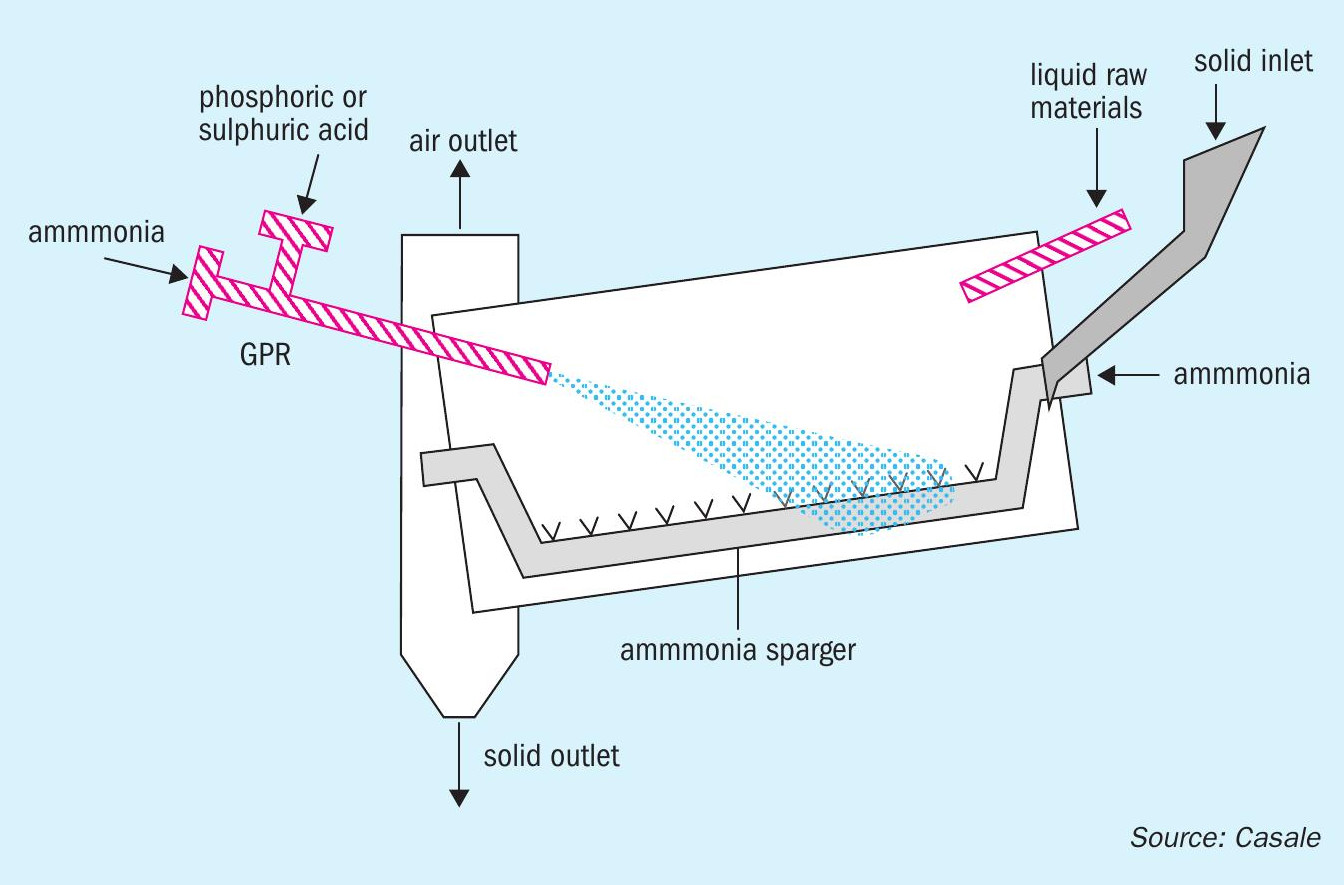
Last but not least, the new GPR can be easily fitted in existing granulator drums without requiring major modifications.
Casale has carried out extensive revamps for IFFCO previously. In 2018, the company successfully completed one of India’s largest ever fertilizer revamping projects. This encompassed a total of 13 IFFCO plants (five ammonia and eight urea units located across three sites) which were originally commissioned between the 1970s and the 1990s. Casale was responsible for the basic design, the supply of proprietary technologies and equipment, and checking detail engineering design.
THYSSENKRUPP INDUSTRIAL SOLUTIONS
Ammonia plant revamping with green hydrogen
Germany’s thyssenkrupp has extensive experience in fertilizer industry revamps. Notable recent project include:
- A contract between thyssenkrupp Fertilizer Technology, a subsidiary of thyssenkrupp Uhde, and Abu Qir Fertilizers Co for the revamp of their Abu Qir 3 urea granulation plant in Alexandria, Egypt
- A 2019 contract from India’s Paradeep Phosphates Limited (PPL) to increase capacity of the existing Prayon DH phosphoric acid plant in Paradeep, Odisha, from 1,000 t/d to 1,400 t/d
- The successful completion in 2018 of a revamp project to increase the ammonia capacity of the SAFCO IV plant at the Al-Jubail complex in Saudi Arabia – then the world’s largest – by more than 11 percent to 3,760 t/d.
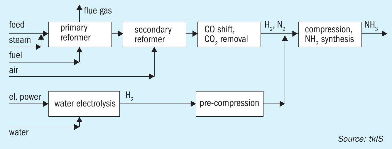
Green hydrogen
Green hydrogen can be supplied to an existing ammonia plant as a revamp option to lower its CO2 emissions. In this scenario, green hydrogen generated by an electrolysis unit is combined with hydrogen from the conventional front-end of the ammonia plant (Nitrogen+Syngas 368, p30).
Plant modifications using green hydrogen can vary between two extreme scenarios:
- Green hydrogen partially or completely replaces hydrogen from the plant’s front-end without changing ammonia production capacity, or
- Green hydrogen is added to increase ammonia production capacity The second option is, however, only possible if the plant’s ammonia synthesis unit is not a capacity bottleneck.
This case study describes the impact at an existing plant of replacing 10 percent of the hydrogen fed to the synthesis unit with hydrogen from an external carbon-free source (Figure 1). It examines the achievable reduction in CO2 emissions. Obstacles to this revamp modification and how these can best be avoided are also discussed.
Impact on process units
The reference case for the simulation is an actual uhde® ammonia plant, although the results presented are equally valid for any ammonia plant based on primary and secondary reforming with stoichiometric process air and with heat recovery for high pressure (HP) steam generation. Electrolysis data are also taken from the uhde® / thyssenkrupp Industrial Solutions alkaline water electrolysis (AWE) process.
- What is the change in reformer fuel demand?
- What is the change in steam export? l Will operating parameters remain within design limits?
- Finally, referring to the main purpose of the change, what is the reduction in CO2 emissions and plant operating costs?
Answers to these questions are covered fully by the original article (Nitrogen+Syngas 368, p30), allowing this summary to instead focus on overall plant performance, CO2 emissions reduction and process control options.
Overall plant performance
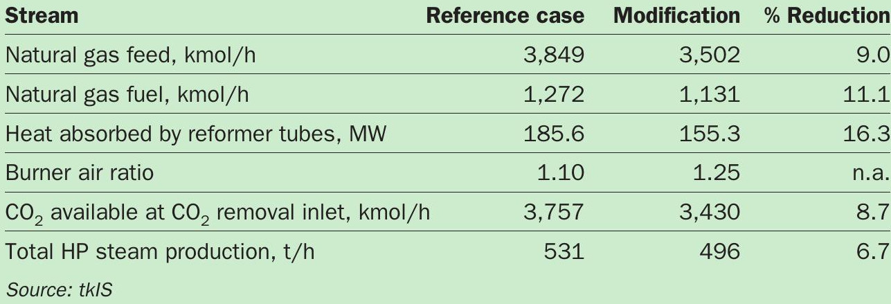
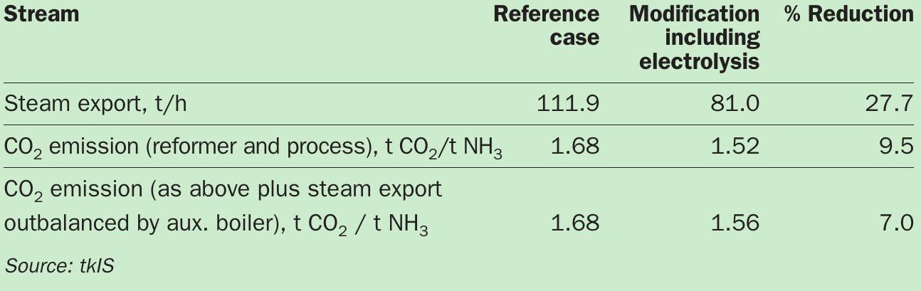
Plant process and performance parameters (for the reference configuration and the green hydrogen modification) are shown in Tables 1 and 2, respectively.
The green hydrogen modification results in a significant drop (27.7%) in the steam export from the ammonia plant (Table 2). This is because less steam is produced from waste heat, yet the requirements of many steam-consuming processes (e.g., refrigeration, process air and syngas compressor turbines) are almost unchanged.
While this can be designed around at a new-build plant, the owner of an existing plant must decide how to handle this steam system shortfall. As a worst case, the reduced steam export resulting from the modification will lead to a steam deficit in another unit (e.g., a urea plant) which then need to be compensated for by higher production in the auxiliary boiler. In other cases, however, lower steam export may be acceptable, if steam consumption can be replaced by using electric power or other alternative forms of energy, for example.
CO2 emissions reduction
The addition of 10 percent green hydrogen reduces total plant CO2 emissions – from the reformer stack and CO2 vent – by about 10 percent, both in absolute terms and per tonne of ammonia production. However, in cases where the lower steam export is replaced by steam generated using a gas-fired auxiliary boiler the reduction is only seven percent – if the extra CO2 emissions are considered, which seems fair.
Process control options
In the conventional plant, adjustment of the hydrogen-to-nitrogen ratio (H2/N2 ) is made by regulating the feed flows of natural gas and process air. This is typically achieved by keeping the natural gas constant and adjusting the process air so that the H2/N2 stochiometric ratio of the feed to the synthesis loop is close to three. But this becomes more complicated in the modified system as – with the addition of an external green hydrogen feed – a third variable comes into play.
In one scenario, the supply of external green H2 will fluctuate due to variations in the renewable power at the electrolysis unit. In this scenario, the ammonia plant will have to cope with and balance out greater fluctuations than usual. However, an instant reaction is not always required because the hydrogen from the conventional front-end acts as a buffer, and small changes in the H2/N2 ratio will only result in a slightly lower conversion.
In contrast, the other green hydrogen supply scenario, where the electrolyser has continuous renewable power without fluctuation, is perfectly suited for H2/N2 ratio control. This is because the electrolyser load and green hydrogen supply can be adjusted within seconds, as this system has much less inertia than the ammonia plant front-end.
Other benefits
There are other ways to add an external stream of green hydrogen to the ammonia production process, as well as the option shown in Figure 1. One option, for example, is to use this H2 as a hydrogenation stream for desulphurisation, thereby avoiding the usual H2 recycle. Another option is to use a dedicated compressor to compress green H2 to synthesis pressure and combine the streams there. This could help with the steam export shortfall highlighted above by saving steam consumed by the syngas compressor train.
Conclusions
There are a number of factors that need to be considered when revamping an ammonia plant with green hydrogen and replacing part of the hydrogen from the front-end with an external source. These include:
- Secondary reformer outlet temperature
- Energy balance of the convection bank
- Gas temperature between reformed gas waste heat boiler and superheater
- The availability of CO2 for downstream products
- Steam export
- Process control if the external H2 feed is fluctuating.
However, there are ways to avoid any adverse impacts, as described in this summary and the original article (Nitrogen+Syngas 368, p30).
STAMICARBON
Stepwise approach to revamping urea plants
Although urea plants begin their life as state-of-the-art, they inevitably age and become outdated over time. During the plant’s lifetime, operators have to cope with technical challenges such as corrosion and leakage – as well as dealing with external changes in legislation, emission requirements, market conditions, and competition.
Although well known for designing new urea plants, Stamicarbon, the innovation and license company of Maire Tecnimont Group, has also successfully executed more than 100 revamping projects. This extensive experience has allowed Stamicarbon to establish a systematic and stepwise approach that gets the best out of any urea plant revamping project.
In general, a change in the status quo and the subsequent decision to revamp a urea plant has an initial trigger and driving force. The most common drivers and motivations that trigger the start of the revamping process are:
- Capacity increase (feedstock/utility availability)
- Product diversification (e.g., DEF, UAN) l Reduction in energy consumption
- Equipment replacement
- Safety improvement
- Legislation and environmental restrictions
- Competition.
Each of the above drivers have different stakeholders with a range of interests and budgets. They are also subject to different boundary conditions such as: the local market, long- and short-term company vision, economics, ambitions, governmental policies, national and international standards, etc.
Before starting the revamping process, Stamicarbon advises drawing up a good plan of approach. This plan needs to include a clear overview of the overall chemical complex, the company’s investment plans, boundary conditions, and limitations.
A urea plant is typically part of a larger chemical complex consisting of at least one ammonia plant and a utility plant. It is often the characteristics of these plants that dictates the limitations of the urea plant revamping project. During the revamp, the scale of investment and the impact of the capacity increase will generally be higher for these plants, compared to the urea plant alone.
The constraints within the battery limits of a urea plant should also be clearly identified. Typical examples are:
- The capacity limitation of rotating equipment – such as high-pressure carbamate and ammonia pumps and the CO2 compressor
- The mechanical integrity and capacity limits of synthesis equipment
- The layout of the revamp – if the proposed revamp design requires significant modifications to the structure and piping, this has a significant impact on the revamp’s technical and economic feasibility
- The availability of excess ammonia
- Steam pressure and steam availability
- The cooling water system.
Each urea plant and its status quo are unique. The most successful outcomes are therefore achieved when long-term planning is included in the revamp project and its plan of approach. Thinking further ahead is beneficial as it allows the revamp design to be executed stepwise over time. Preparing a long-term plan also increases the success rate of a revamp project by ensuring it fits in with the company’s investment plan and aligns with the long-and short-term company vision.
An example of a stepwise approach to urea plant revamping is provided below.
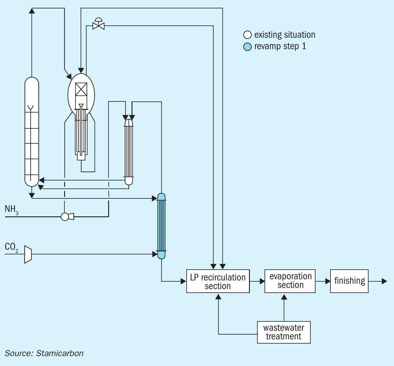
Step 1 – stripper replacement
The basis of this example is a typical urea plant with Stamicarbon CO2 stripping technology. In this instance, the stripper in the urea synthesis section is at its mechanical end-of-life and consequently this equipment needs to be replaced in the next turnaround. This situation is shown schematically in Figure 1.
Without making a long-term plan, there are three stripper replacement options:
- Option A. Install an identical replacement made of similar construction material and with a similar amount of tubes. During its lifetime, it is a common for the stripper tubes to become thinner due to corrosion. Stripper performance is enhanced because these thinner tubes allow a higher tube load to the stripper with a corresponding increase in plant capacity. However, installing a new stripper with an equal number of stripper tubes will reduce plant capacity by bringing it back to its original design value. This option is therefore less favourable.
- Option B. It is possible to compensate for the effect of lower plant capacity, as highlighted in option A. This is achieved by installing a few more tubes while decreasing the tube pitch to keep the stripper’s shell dimensions the same. Furthermore, the quality of the stripper can be increased by applying the latest design standards (e.g., a material upgrade, the use of a pressure safety valve instead of a rupture disc, installing an improved liquid distribution system etc.). After installation, this stripper will then meet the higher capacity achieved immediately prior to the revamp.
- Option C. The same modifications as mentioned under option B are applied. But more tubes are installed to enable future plant expansions. However, a long-term plan is required to determine the limits and the optimum number of tubes necessary to accommodate the plant’s desired future capacity.
Materials of construction also have an impact. Traditionally, strippers are constructed from BC.05 (25-22-2) material. While the latest standard construction material is Safurex® (BE.06). The use of Safurex® over BC.05 has the following advantages:
- Improved corrosion resistance: with Safurex® , a lower oxygen concentration is used in the carbon dioxide supply for passivation purposes, extending the lifetime of equipment. A lower oxygen concentration also reduces the airflow, and thus the inert flow to the synthesis loop, creating an operational margin for further capacity increase.
- Material thickness: Safurex® tubes can have a thinner wall thickness compared to BC.05. Safurex® tubes therefore have a larger internal diameter. Consequently, a Safurex® stripper will have a higher tube load compared to a BC.05 stripper, assuming an equal (liquid) film layer in the stripper tubes.
- Weight: a Safurex® stripper is substantially lighter than a BC.05 stripper when installing the same number of tubes – resulting in economic advantages, e.g. less steel.
- Redundancy of expansion bellows: because the expansion coefficient for the Safurex® material approaches the expansion coefficient of the carbon steel, the expansion bellows usually used for BC.05 strippers are no longer required.
In both a Safurex® and BC.05 stripper, more tubes can be installed within the same shell diameter by reducing the tube pitch. No modifications to the high-pressure piping and civil works are required when the same shell diameter is maintained. Alternatively, the scope for increasing the shell diameter, without the need for modifications of the plant structure and piping, can be investigated. This allows the installation time to be minimised, even in a short turnaround of 1-2 weeks.
Step 2 – capacity increase via a medium-pressure add-on section
Option A in step 1 can be ruled out in subsequent steps as it results in a reduction in achievable plant capacity compared to the capacity prior to revamp. That leaves options B and C.
After the replacement of the stripper in step 1, there is again scope to increase plant capacity in step 2 until the next bottleneck limitation is met. In option B, it is the stripper that becomes the next bottleneck. In option C, in contrast, the stripper will not become a bottleneck as it is designed to meet future requirements. Capacity can therefore be increased in option C up to the limitation of the CO2 compressor.
The plant therefore requires an additional revamp step to overcome either the bottleneck of the stripper limitation (in option B) or the compressor limitation (in option C). Revamping the CO2 compressor is costly compared to the limited capacity gain this delivers. However, by applying a medium-pressure Add-On concept instead, the plant capacity can be increased without modifications to the synthesis equipment (Figure 2).
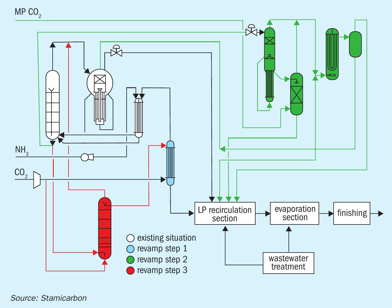
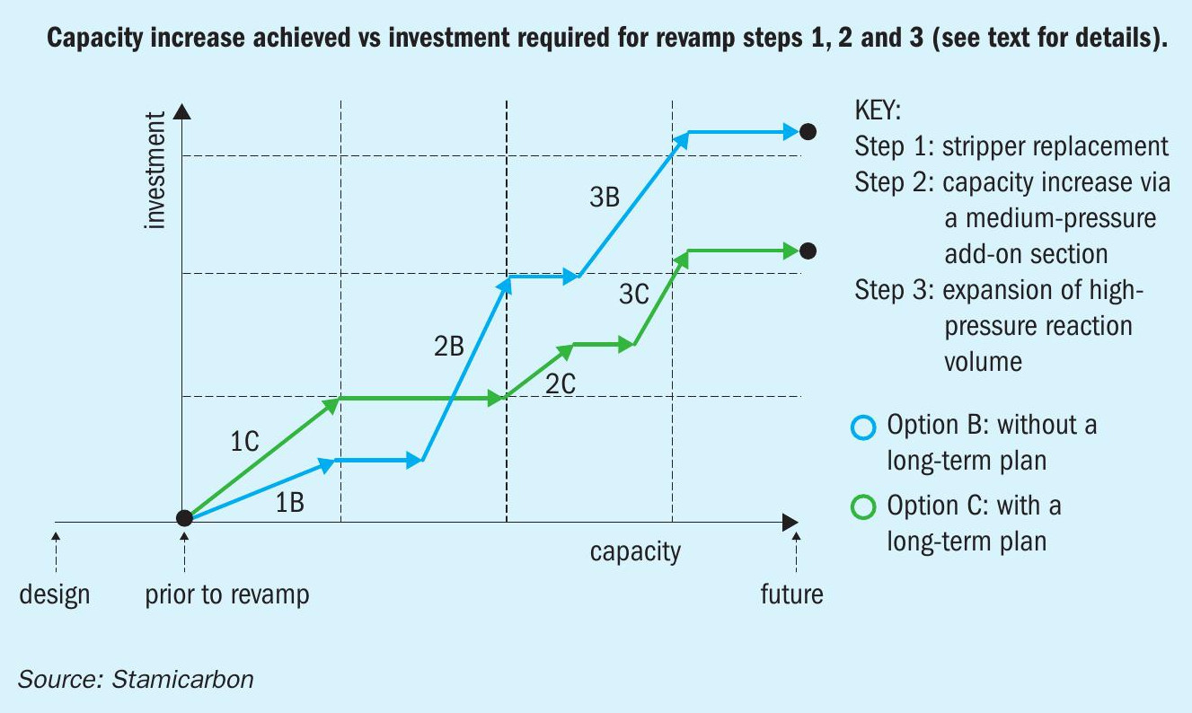
In the medium-pressure Add-On concept, part of the synthesis liquid leaving the urea reactor is processed in a parallel medium-pressure section. In this configuration, the stripper operates at maximum loading, a consideration that determines the dimensions of the medium-pressure section. The additional carbon dioxide required by the medium-pressure section is provided by a medium-pressure CO2 compressor.
Step 3 – expansion of high-pressure reaction volume
The next revamp step for achieving the desired future plant capacity requires the installation of additional reaction volume downstream of the existing reactor, e.g. by installing a pool condenser, pool reactor, or after reactor (Figure 3).
Option B has a smaller stripper and larger medium-pressure Add-On section. As a result, option B increases the carbamate recycle sent back to the synthesis section. Therefore, to reach the same desired increase in plant capacity, option B will require more additional reaction volume, compared to option C, resulting in higher investment costs.
Completion of these three revamp steps will achieve the desired future plant capacity, as shown schematically in Figure 4.
Impact of the stepwise approach on long-term investment
The impact of revamping on investment costs, with or without a long-term plan for the urea plant, is shown in Figure 5 for comparison purposes. With a long-term plan in place, although the initial investment in the first revamp step (stripper replacement) is higher, in the end, overall investment is lower. This is because the larger stripper design is part of a stepwise plan to reach a higher plant capacity in future.
Conclusions
There are several ways to optimise operational urea plants. The choices are typically between revamping concepts for increasing capacity, reducing energy consumption, or cutting emissions. These concepts are used as the basis for the revamp design, which can also include project-specific tailored modifications.
We recommend that each revamp project should follow a stepwise approach. Using this philosophy, a long-term plan is prepared and then executed in a series of steps – to fit within a given timeline and the available budget.
Revamping is complex process based on teamwork. For a successful revamp, all elements and parties need to work together on an agreed plan and approach to project execution. Selecting a suitable and reliable licensor and contractor is also an important part of the revamp process. These partners provide the broad technological know-how and a portfolio of technological concepts. At Stamicarbon, these revamp capabilities are being improved through continuous innovation and development based on proven experience.