Sulphur 407 Jul-Aug 2023
31 July 2023
Freezing the furnace
CLAUS FURNACE DESIGN
Freezing the furnace
Debopam Chaudhuri of Fluor Daniel India Pvt Ltd and Michiel Baerends of Fluor B.V. Netherlands investigate how SO2 impacts the Claus furnace temperature in an SRU and the ways to mitigate it. This article studies the extent of quenching experienced in the Claus furnace with varying amounts of SO2 in the Claus feed. A case study is presented based on real operating data of a refinery Claus plant with a feed gas cocktail that includes substantial SO2 recovered from a regenerative flue gas desulphurisation unit.
The classical feed gas streams to a sulphur recovery unit (SRU), originating from the amine regeneration and the sour water stripping units, contain varying amounts of H2S as the sulphur source. The H2S in the acid gas streams is captured as elemental sulphur utilising the modified Claus reactions. The process involves burning the acid feed gas with a sub-stoichiometric amount of air – just enough to combust only a third of the H2S to SO2. The SO2 thus formed reacts with the unconverted H2S to form sulphur.
The main reactions involved are:
H2S + 11 /2 O2 → SO2 + H2O (1)
2H2S + SO2 → 3S + 2H2O (2)
3H2S + 11 /2 O2 → 3S + 3H2O (3)
Reaction 1 is highly exothermic, while reaction 2 is endothermic, with a net effect of exothermicity for the overall reaction 3.
If SO2 is also present in the feed stream to the SRU it reduces the air requirement, as well as impacting (lowering) the furnace temperatures.
Another reaction of importance is the destruction of ammonia (NH3) in the presence of air.
2NH3 + 11 /2 O2 → N2 + 3H2O
It is generally agreed that the Claus furnace needs to be hot enough to ensure near complete destruction of ammonia to nitrogen, and the target typically followed globally for a standard Claus plant is 1,250°C.
The requirement to achieve at least a certain ‘threshold’ temperature in the Claus furnace to destroy relevant impurities can clash with the tendency SO2 has, in terms of reducing the very same temperature. This article explores some ways and means to counteract this tendency; and meet required Claus furnace temperature even in the presence of some SO2 in the feed gases. First, however, some discussion is warranted on possible sources of SO2 in Claus feed gases.
Where does the SO2 come from?
In a refinery setting, FCC regenerator flue gas (if the FCC feedstock is unhydrotreated VGO or a resid feed) can have appreciable SO2, which in some cases may be removed by a regenerable SO2 scrubbing system. This implies that the SO2 removed from the FCC regenerator flue gas is released by the regenerator (stripper) of the regenerative system; and requires processing in the refinery SRU. Similarly, in case the refinery has an oil-fired power plant (power plant steam boilers fired on residue fuel oil having considerable amounts of sulphur), the flue gas would contain high amounts of SO2, which also might utilise a regenerable SO2 scrubbing system, resulting in SO2 ending up in the SRU feed mixture. Other possible SO2-rich flue gases in refinery settings could be flue gases from various fired heaters using residual fuel oil, flue gas from the fluid coker regenerator or spent acid alkylation flue gas. Even a Claus incinerator flue gas might need to use a regenerable de-SOx process if the sulphur plant is designed without a TGTU, as the incinerator flue gas would then contain appreciable amounts of SO2.
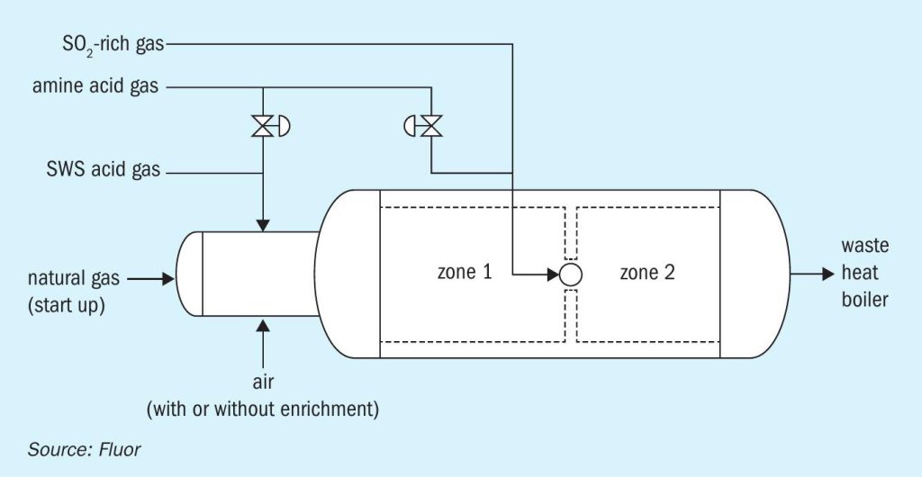
As indicated above, regenerative SO2 flue gas removal processes typically remove SO2 from the flue gas stream using a solvent (for example, an amine-based solvent, such as in the Cansolv process) to absorb the SO2. The ‘rich’ solvent is then regenerated to release the SO2 back. The released SO2 is then routed to an SRU, along with the normal acid gas streams. Fig. 1 depicts a simplified schematic of a regenerative de-SOx process.
The impact of SO2 in feed gas
The presence of SO2 is both beneficial and potentially harmful for the Claus process.
As each mole of SO2 replaces 1.5 moles of O2 required in the furnace, the air flow rate can be reduced (unloading the air blower), which also reduces the ‘tail gas’ flow through the unit, which, after all, has N2 from combustion air as the main component. In fact, while increasing elemental sulphur output, additional SO2 added to the feed cocktail hydraulically unloads the unit. This seems a favourable side effect of having SO2 in the feed gas.
On the other hand, the SO2 induces a substantial ‘quenching’ effect on the Claus furnace temperature, due to the loss of exotherm in the Claus furnace. This in turn presents challenges in meeting the necessary temperature required for destruction of NH3 and other impurities.
A theoretical assessment of how the SO2 in the feed stream impacts the overall reaction and capacity of the unit is made here for illustrative purposes. For this it is considered that the Claus furnace receives a constant feed gas flow of 100 kgmol/h, with a varying composition. For the initial case, it is theoretically assumed that the gas fed to the furnace is pure H2 S, and for the subsequent simulation runs, the feed gas composition is changed, increasing the SO2 content in steps of 5%, but leaving the total feed gas flow the same, and thus leading to the same sulphur product rates, around 75 t/d. The results of the simulation runs are shown in Table 1.
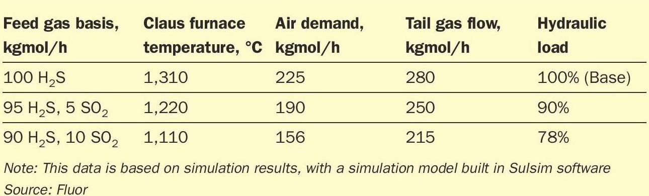
Table 1 illustrates how adding limited amounts of SO2 (relative to the amount of H2S), has a significant, favourable impact on the air demand (lower) and tail gas flow / hydraulic load through the unit (lower). At the same time, it can be observed that even small quantities of SO2 have a very substantial, and unfavourable, impact on furnace temperature (200°C lower when 10% of the H2S feed is substituted by SO2), making destruction of impurities significantly harder to achieve.
Managing the freeze
Design modifications are necessary in the SRU to manage the ‘cooling’ effect of co-processing SO2. The design options available to maintain proper furnace temperatures in the Claus furnace are well known. They include feed preheat, air preheat, fuel gas cofiring, oxygen enrichment, and furnace design adaptations, or a combination of two or more of these options.
Feed preheat
Feed preheat entails heating up one or more of the feed gas streams, as needed. Similarly, the combustion air supplied to the Claus furnace may also be heated up. Typically, the steam generated in the waste heat boiler of the Claus plant is used as the heating medium, and the amount of preheat available is then limited by the steam pressure available. With steam pressures from Claus waste heat boilers typically in the region of 40 bar (condensing temperature around 250°C), this leads to practical pre-heat temperatures somewhat below 250°C. Any additional heat input would require the implementation of fired heaters, in-line burners or electric heaters. For the example presented in the previous section, while operating with the 90 kgmol/h H2S + 10 kgmol/h SO2 feed gas stream, preheating the amine acid gas to 220°C will ensure a furnace temperature in the range of 1,160°C, while preheating both the air and the feed streams takes the furnace temperature to 1,210°C.
Fuel gas cofiring
Fuel gas cofiring may be applied to increase the furnace temperatures. Typically, natural gas is a preferred for cofiring in the Claus furnace. A continuous application of fuel gas co-firing may not be recommended for various reasons, the major one being the fact that it increases the potential of ‘soot’ deposition in the downstream catalytic reactors. It should also be noted that cofiring, while helping to increase the furnace temperature, offsets the hydraulic advantages of coprocessing SO2 as it needs additional air for combustion, adding to the gas flow through the unit. For comparison, adding 5 kgmol/h of natural gas to the 90/10 H2S/SO2 feed gas stream increases the furnace temperature to 1,230°C, but also makes the unit run at 93% compared to its base hydraulic load (instead of at 78%, which would have been the case without co-firing). Co-firing also introduces an operating cost for the fuel gas, which may be recovered by the value of the extra steam generated as a result of co-firing.
Oxygen enrichment
Oxygen enrichment is a very logical option for enhancing furnace temperatures. Eliminating a portion of the ‘inert’ nitrogen molecules from the air supplied for the firing in the furnace allows a higher temperature with the same amount and composition of acid gases. Different levels of oxygen enrichment may be implemented – low level (typically up to 28 vol-% oxygen, oxygen added directly to the combustion air line), mid level (typically up to 45 vol-% oxygen) or high level (theoretically up to 100 vol-% oxygen). An important side benefit of implementing oxygen enrichment is that it reduces the hydraulic load on the unit, making it physically smaller. With the example presented in the previous section, while operating with the 90/10 H2S/SO2 feed gas stream, in case low level oxygen enrichment level (28 vol%) is implemented, the furnace temperature increases to 1,225°C, while reducing the hydraulic load to 63% compared to the base case. The obvious drawback of this option is the increase in the cost of operating the unit, associated with continuous usage of oxygen. In addition, design complexities of the Claus burner and furnace and even the overall Claus unit are introduced as the enrichment level increases.
Furnace design adaptations
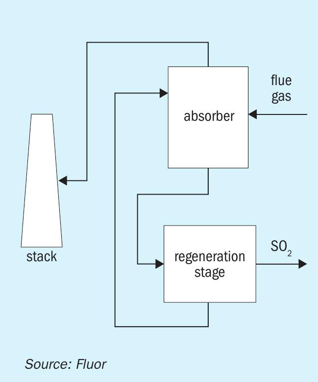
Lastly, there are multiple options of furnace design adaptations available to manage furnace temperatures in the Claus furnace. These are mostly licensor specific, but mostly revolve around regulating gas streams to the furnaces in separate zones. A two-zone furnace in effect allows the combustion to happen in two stages (Fig. 2). The front section, to which all air is directed, operates at higher ‘oxidation extent’ and therefore at a higher temperature, than would be possible for a single zone furnace. The SWS gas is exclusively combusted here, with a considerable portion of amine acid gas bypassed, allowing the front section to operate with a high enough temperature to destroy the ammonia (typically greater than 1,250°C). For the back end, where there is no NH3 to destroy (as all NH3 containing SWS gas was directed to the front end) a temperature above 1,050 or 1,100°C would be acceptable to ensure destruction of hydrocarbons1,2 .

Case study
The data presented in this case study is based on the real operating data of a refinery that is undergoing a revamp to replace two small and very old sulphur plants which have been facing age-related issues in operation. They have been heavily dependent on continuous maintenance and have been experiencing emission issues as the sulphur load of the refinery has been gradually increasing.
The refinery processes a moderate to high sour crude. One of the products of the refinery is refinery fuel oil which supplies the power generation plant within the refinery. A major portion of the vacuum residue thus finds its way out as fuel oil for this power plant. A thermal cracking unit ‘prepares’ the fuel oil, while the co-produced cracked distillates are treated further (desulphurisation) in the hydrotreaters, wherein the cracked distillates are desulphurised along with the straight run light and middle distillates. The balance amount of the vacuum residue is either exported as bitumen or as bunker fuel oil, after adding necessary amounts of cutter stock to it.
The power plant also includes a flue gas desulphurisation unit to capture the SO2 from the flue gas (originating from the burning of heavy fuel oil, containing significant organic sulphur). The SO2 removed from the flue gas is subsequently released from the solvent regeneration step; and must be routed to the new sulphur recovery unit for conversion to elemental sulphur.
The refinery is thus opting for a new sulphur plant that is capable of processing the necessary amounts of acid gas streams generated from the upstream amine regeneration and sour water stripping units as well as co-processing a considerable amount of SO2 as generated from the regenerative flue gas desulphurisation unit of the power generation unit.The amount of SO2 that needs to be co-processed in this new unit was proving to be a bottleneck, and hence a detailed assessment was performed on the means and methods via which the plant capacity enhancement could be achieved.
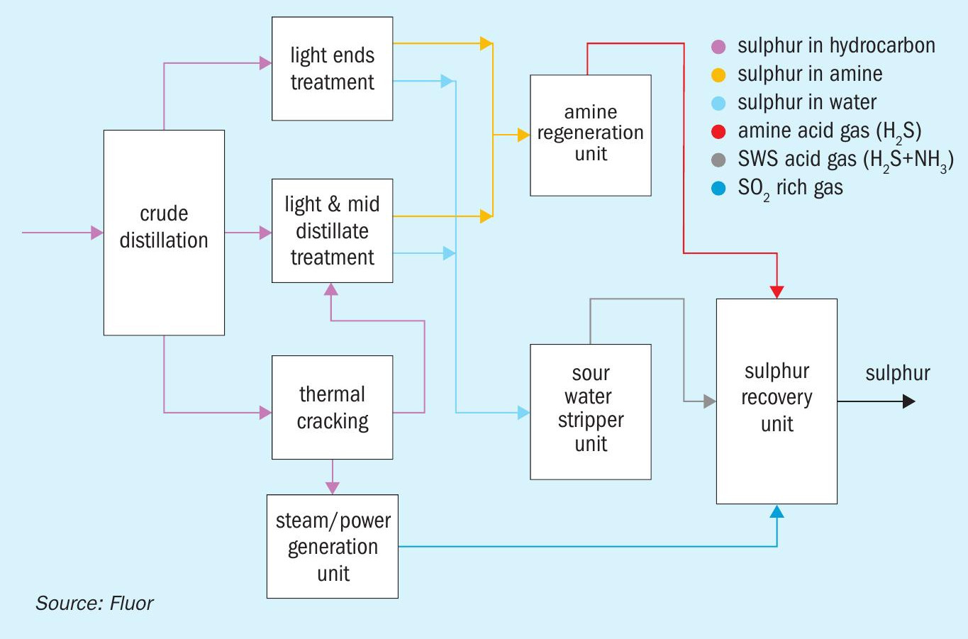
Fig. 3 shows the sulphur map for the refinery.
The expected feed gas compositions and plant capacity are provided in Table 2 corresponding to a sulphur production capacity of 200 t/d.
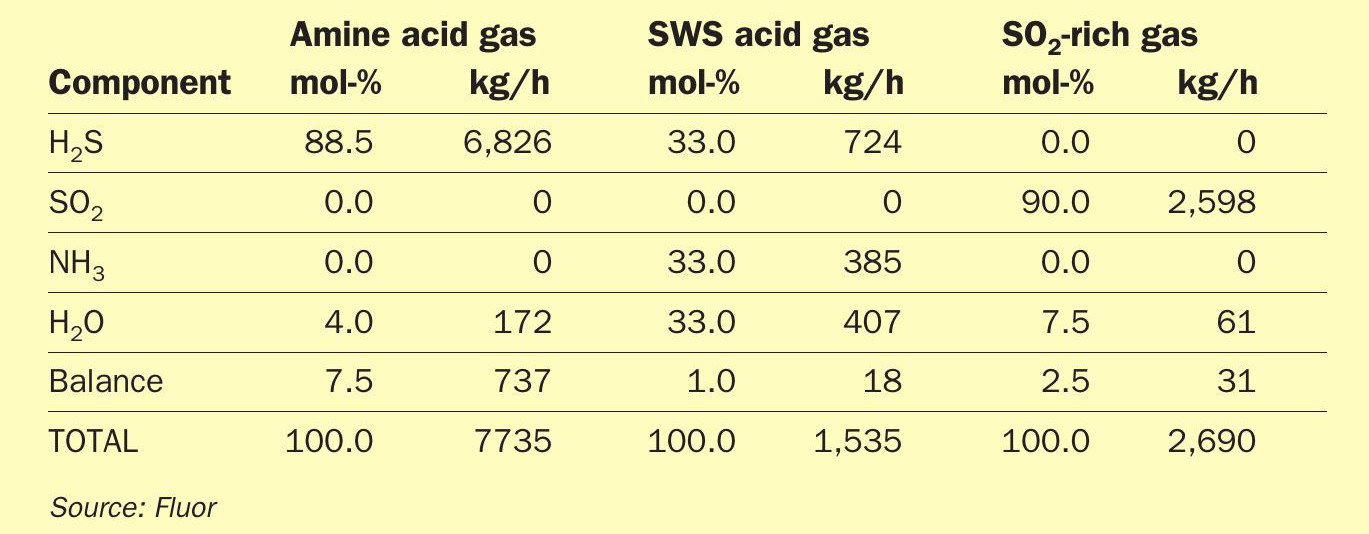
As can be derived from the Table 2, the feed gas to the new Claus plant contains more than 10 vol-% of SO2. As already discussed, with such high amounts of SO2, maintaining proper furnace temperatures becomes challenging. Since the overall gas contains almost 6.5 vol-% of NH3, the importance of maintaining the right furnace temperature is vital.
The expected Claus furnace temperature when processing this feed gas cocktail in a single-stage furnace is a mere 850°C, which is woefully inadequate to ensure impurities destruction. The alternatives available to allow the Claus plant to operate with acceptable furnace temperature, thus allowing to process such a stringent feed gas cocktail, are discussed in the next section.
The alternatives and the path forward
The possible methods for improving the Claus furnace temperature have already been mentioned. In this section each of the methods are explored to improve the furnace temperature for the case study sulphur plant.
Feed preheat
Table 3 defines the impact of preheating on the case study data.
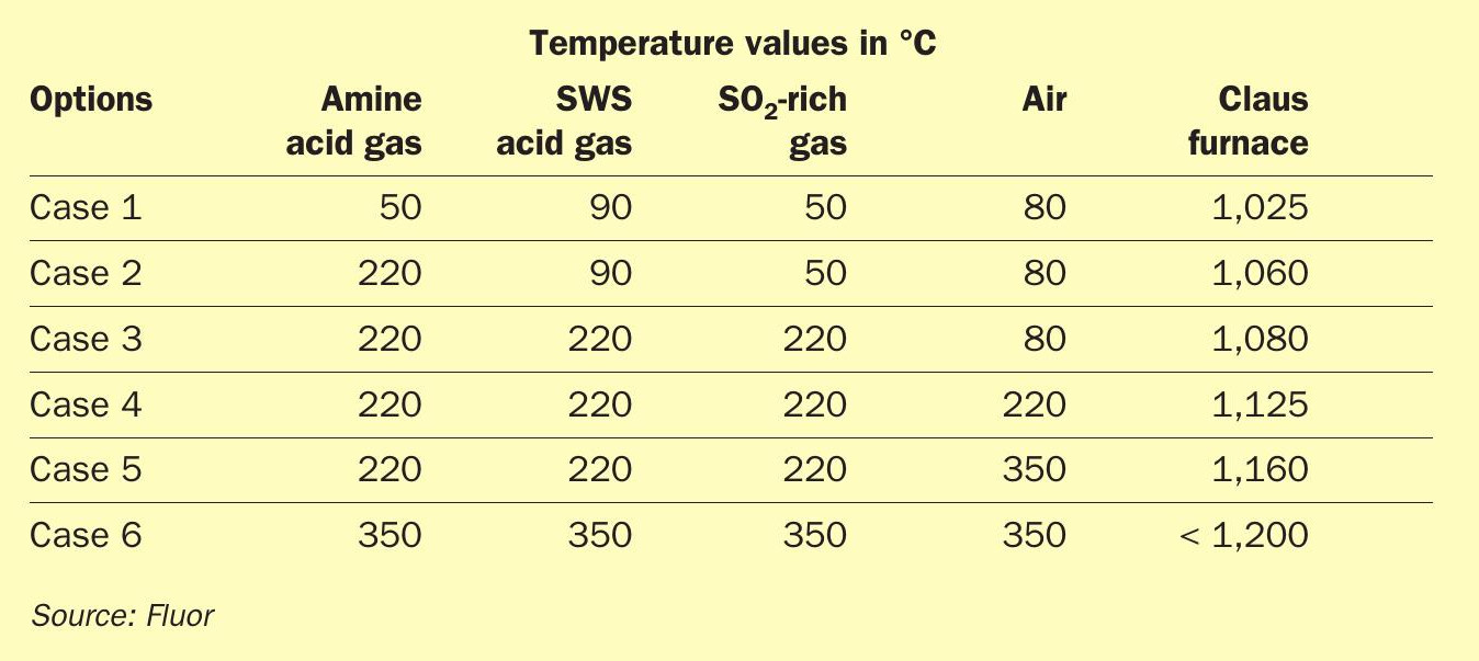
The following options were studied:
- Case 1: no preheating – base conditions;
- Case 2: preheat amine acid gas only (including TGTU recycle) to at least 220°C;
- Case 3: preheat all acid gas streams (amine acid gas, sour water stripper acid gas and SO2 -rich gas) to at least 220°C;
- Case 4: preheat all acid gas and air stream to at least 220°C;
- Case 5: preheat all acid gas stream to at least 220°C and preheat air to at least 350 °C;
- Case 6: preheat all acid gas and air stream to at least 350°C.
Preheating up to 350°C may be achieved by adding an electric heater downstream of the stream air preheater.
From Table 3 it is evident that preheating alone would not be sufficient to achieve the necessary Claus furnace temperatures, and hence alternative methods were investigated.
Fuel gas cofiring
Fuel gas cofiring may be applied to increase the furnace temperatures, but due to very stringent feed gas compositions high amounts of natural gas need to be burnt in the Claus furnace. Burning around 175 kg/h of natural gas (containing about 90% methane, the rest heavier hydrocarbons) achieves a furnace temperature of 1,100°C, while to reach a temperature above 1,250°C, 600kg/h of natural gas is envisaged. As already specified, a continuous application of fuel gas firing is typically not recommended for various reasons, and hence was not considered further for any subsequent assessments.
Oxygen enrichment
The furnace temperatures achieved with various levels of oxygen enrichment is shown below:
- Low level (28% O2): 1,100°C
- Mid level (45% O2): 1,210°C
- High level (60% O2): 1,260°C
Thus, when relying on oxygen enrichment alone, the Claus burner/furnace needs to be designed with high level oxygen enrichment to ensure a high enough furnace temperature for ammonia destruction. The amount of oxygen required would add up to around 75 t/d.
Two-zone furnace design
For the case study, a two-zone furnace was conceived where the amine acid gas flow was split between the front and rear end of the furnace.
The front zone furnace temperatures achieved with a two-zone furnace design are represented below:
- 80:20 amine acid gas split: 1,175°C
- 70:30 amine acid gas split: 1,210°C
- 60:40 amine acid gas split: 1,270°C
The above results indicate that a two-zone furnace designed with a 60-40 split just meets the 1,250°C furnace temperature requirement in the front zone.
Using oxygen enrichment, combined with preheat, although a viable option, was ruled out due to the high operating costs to sustain continuous oxygen usage. The case study refinery did not have a ready source of oxygen; and importing liquid oxygen from an external source or investing in a dedicated oxygen generation unit using PSA/VPSA technology was found to be economically unattractive. For refineries that have a ready and cheap source of oxygen this may be the preferred route.
For the case study, the two-zone furnace design was selected as the preferred option, complemented with some feed preheat to allow for operating flexibility, mainly to achieve adequate furnace temperatures at a range of possible operating scenarios especially during partial turn down operation when the amine acid gas flow would reduce more than the SO2-rich gas flow.
Summary
Small amounts of SO2 in the Claus feed gas has a favourable impact on the overall hydraulic design of the sulphur recovery unit, as SO2 replaces air, thus reducing the gas volume leading to smaller sizes for equipment and piping. At higher concentrations of SO2 the positive impact of reduction of air demand tends to be overshadowed by the quenching effect on the Claus furnace, reducing the furnace temperatures below allowable operating limits for proper NH3 destruction. Design modifications are required for Claus plants which co-process significant amounts of SO2 along with the normal feed gas cocktail of H2S and NH3 .
Relatively small amounts of SO2 in the feed gas may be easily managed by feed preheat alone. However, with higher amounts of SO2 in the feed, there is no single, obvious solution available. Instead, application of one or a combination of multiple design modifications will be required. A careful study needs to be performed to select the optimum solution for the specific project application.