Nitrogen+Syngas 388 Mar-Apr 2024
31 March 2024
Towards an emerging hydrogen economy
LOW CARBON HYDROGEN AND AMMONIA
Towards an emerging hydrogen economy
Low carbon intensity hydrogen and ammonia production schemes from KBR, Air Liquide, Mitsubishi Heavy Industries, Casale and Johnson Matthey.
Hydrogen is one of the key solutions for addressing global warming, climate change, and energy security challenges. With current carbon-intensive hydrogen production and green hydrogen likely a longer-term solution, blue hydrogen production, with attractive levelised cost, can provide the much-needed stepping stone to an emerging hydrogen economy worldwide. In order to realise the potential benefit of low-carbon hydrogen production from fossil fuels, a reliable solution is required for a large-scale emerging market.
Ammonia as a hydrogen carrier is also a crucial enabler of the energy transition. While it will take time for renewable energy infrastructure and hydrogen production capacity to be developed at scale, low-carbon ammonia produced from natural gas with additional carbon capture supports the transition phase in the next decades.
—————————————————————————————————————————————–
KBR
KBR’s blue hydrogen technology: 1,000 MW clean hydrogen
KBR has been at the forefront of SMR technology for more than 75 years. Over time, the standard size of KBR ammonia plants has doubled from 1,000 t/d ammonia (NH3) (~300 MW H2 equivalent) in the 1960s, to more than 2,000 t/d NH3 (~600 MW H2 equivalent) in the early 2000s. Since then, plant sizes have increased again, and KBR now has single-train plants in operation producing over 3,000 t/d NH3 (~900 MW H2 equivalent with units of 6,000 t/d NH3 (~1,800 MW H2 equivalent).
Leveraging on this vast experience, KBR recently developed a basic engineering design for a 1,000 MW blue hydrogen plant based on SMR with a minimally-sized post combustion capture unit (PCCU).
KBR’s blue hydrogen technology
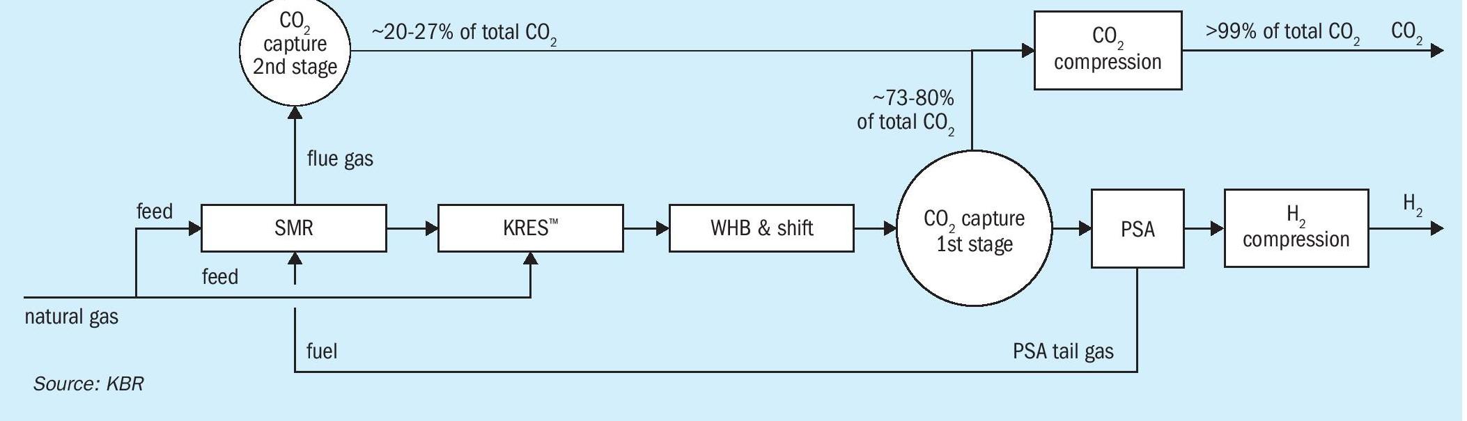
KBR’s blue hydrogen process, H2KPlusSM , (see Fig. 1) is based on the advanced SMR process, which utilises the proven, safe, and reliable, KRES™ technology, which helps reduce capex, opex, and importantly, carbon generation in the process. This technology has accumulated over a decade of experience and has demonstrated both operating and maintenance/reliability advantages.
The key advantages of the proven mega-scale KBR H2KPlusSM process are:
- highest energy efficiency / lowest CO2 generation;
- lowest capex;
- highest reliability / lowest downtime.
There are over 260 SMR units installed globally with the following features:
- 3 to 18 tube rows;
- furnace efficiency: 91~ 94%;
- low NOx designs, (incl. SCR);
- feed pre-heat, up to 625°C;
- flexible control options;
- optimised overall footprint.
KRES™ is the heart of KBR’s blue hydrogen technology. The incorporation of KRES™ offers the potential for reforming up to 30% of the total natural gas fed to the plant by using high-temperature process waste heat exiting the steam methane reformer instead of burning fuel. In addition, KRES™ operates in parallel with the SMR, which reduces front-end pressure drop, resulting in a reduction in the power consumption of the hydrogen compressor (energy saving).
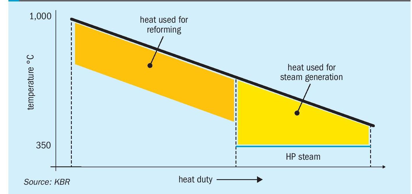
Reformed gas exiting the primary reformer at a very high temperature (~900°C) carries substantial high-grade waste heat. In the conventional reforming process, such high-grade heat contained in the reformer effluent gas is involuntarily degraded by recovering as steam, a relatively lower-grade heat carrier. KRES™ utilises this waste heat instead of consuming natural gas fuel to generate synthesis gas in the reforming exchanger. Fig. 2 illustrates the heat curve of the secondary reformer effluent with KRES™ for reforming instead of steam production.
The addition of KRES™ is not only the most cost-effective route to generate hydrogen but also helps in achieving a mega capacity without a massive increase in SMR size. Being the biggest contributor to the capex in a hydrogen plant, a reduction in reformer size leads to direct capex savings.
By combining these proven technologies, the following advantages are realised in comparison to other plant designs:
- a reduction in the primary reformer size by up to 30% leading to a reduction in fuel usage and thus carbon emissions;
- significantly prolonged waste heat boiler equipment life due to lower temperatures in the inlet of the waste heat boiler (900°C versus 800°C);
- inherently safer operation with no pure oxygen in the system.
For CO2 recovery levels up to 99%, a PCCU unit is integrated into the process flow scheme. Through the use of a PCCU, up to 98% of the CO2 generated in the flue gases can be recovered. This supplemental CO2 capture allows for an overall unit CO2 recovery of up to >99%. In addition, by utilising a PCCU, the impact on the front-end equipment sizing associated with generating excess syngas for utilisation as fuel is avoided.
KBR’s blue hydrogen process for 1,000 MW
The process flow scheme for the design of hydrogen production for a 1,000 MW plant is depicted in Fig. 3. The PCCU provides much better flexibility for a large-capacity plant without any impact on the sizing of the front-end section of the plant.
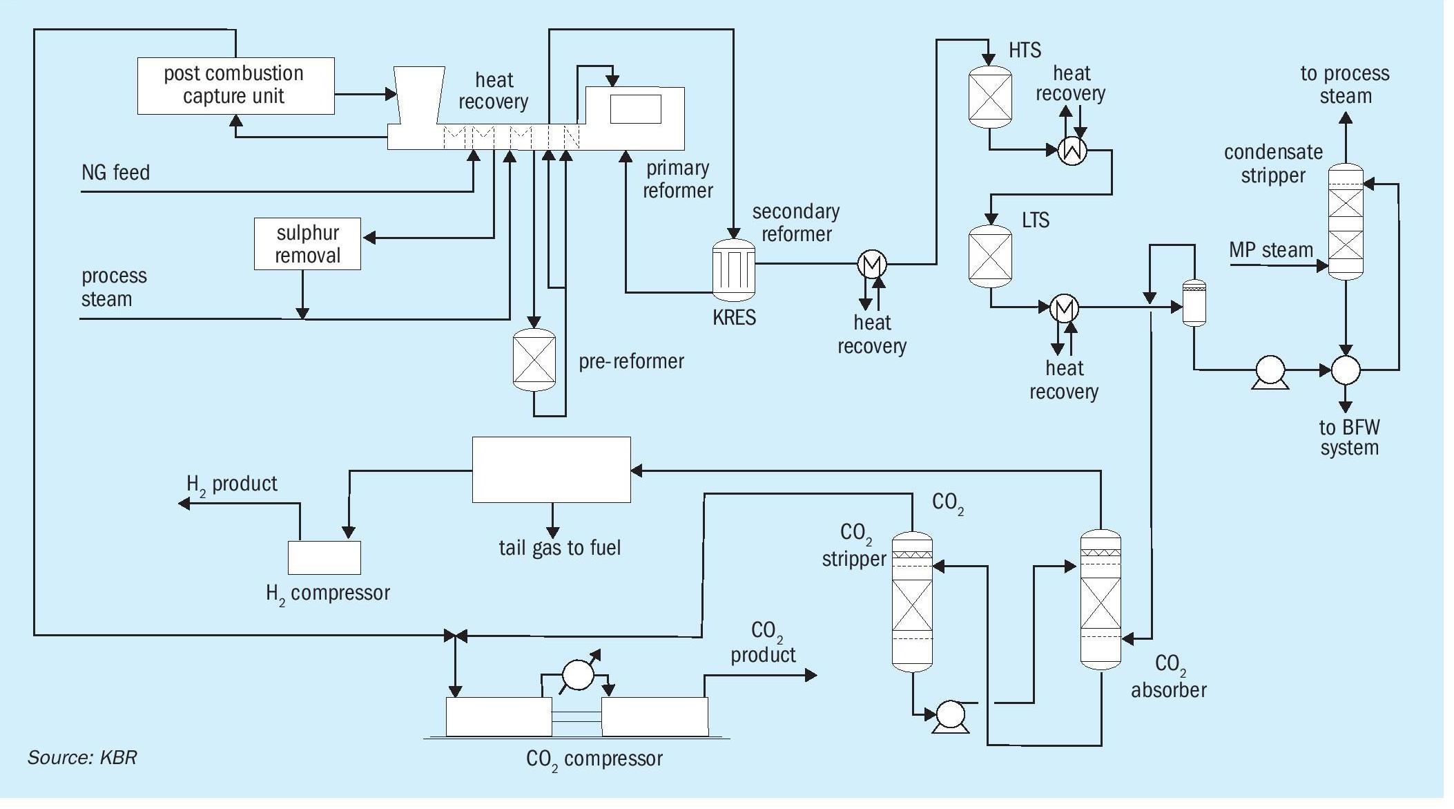
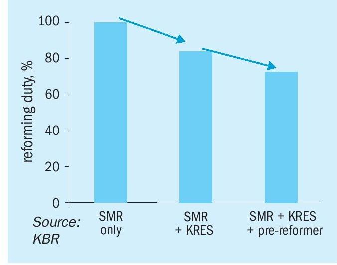
For further reduction in the opex and capex of the plant, a pre-reformer is added in a large capacity plant, which contributes roughly to a 10% reduction in the size of the reformer.
The pre-reformer, as its name suggests, is installed upstream of the SMR. It utilises the low-grade heat from the convection section of the reformer to reach the reaction temperature and reform higher hydrocarbons as well as methane to hydrogen. With the combined use of KRES™ and the pre-reformer, there is not only a significant reduction in the size of the reformer but also a reduction in the fuel consumption leading to a smaller PCCU. Fig. 4 represents the comparison of radiant duty with the addition of KRES™ and a pre-reformer.
Downstream of reforming, typical high temperature and low temperature shift reactors in series are used to optimally convert carbon monoxide to carbon dioxide and hydrogen via water-gas shift reactions. The carbon dioxide produced in the reforming section and shift reactors is removed using BASF’s OASE White dual-stage CO2 removal process. The system is well integrated with process waste heat used to support heating demands in both the pre-combustion and post-combustion CO2 capture units. The hydrogen product is cleaned further to 99.9% purity by the pressure swing adsorption (PSA) process.
To increase efficiency and decrease capex at the same time, various features have been included in the system, such as:
- Pressure in the system is maximised to the allowable limits: Since the reforming reaction is favoured at lower pressure and high temperature but equipment sizing is reduced due to lower volumetric flow rate, there is a fine balance for selecting the optimum operating pressure. KBR used the unique experience of operating a primary reformer at well above 30 bar for an ammonia plant to select the optimum pressure for a 1,000 MW blue hydrogen plant.
- Use of HP flash scrubber: This enabled scrubbing of HP flash gas to remove CO2 from HP flash gas. This CO2, would otherwise have landed in the fuel system of the primary reformer leading to a slight increase in size of PCCU.
- Use of tail gas compressor: There is a trade-off between recovery in the PSA unit and pressure of the tail gas. By addition of a tail gas compressor, maximum recovery of hydrogen (more than 87%) even with a high purity requirement of 99.9% is ensured.
To conclude, KBR’s efficient and reliable reforming technology, in combination with a small post-combustion capture unit (PCCU), leveraging economies of scale, will deliver 1,000 MW hydrogen with an unparalleled carbon capture rate of over 99% using industry-standard and well-proven equipment sizes and catalysts.
—————————————————————————————————————————————-
AIR LIQUIDE AND KBR
ATR-based low carbon ammonia
Ammonia plays an essential role in the energy transition, serving existing markets and functioning as a hydrogen carrier for trans-continental shipping. To ensure economically viable and sustainable ammonia supply chains, the reduction of carbon footprints and the scale-up of production are imperative. In response to this challenge, KBR and Air Liquide have formed a collaborative alliance, bringing together their expertise in autothermal reforming (ATR), air separation, carbon capture, and ammonia production to provide customers with comprehensive and optimised solutions, serving as a one-stop shop for the industry.
KBR and Air Liquide’s collaboration aims to overcome economic and environmental obstacles by jointly focusing on ATR-based low-carbon ammonia technology for the sustainable supply chains of the future.
Air Liquide’s role in the collaboration is underscored by its proven track-record as an operator and designer, particularly in low-carbon and renewable hydrogen technology
- Oxygen-blown ATR technology: Air Liquide has established its leadership in oxygen-based ATR technology through nearly seven decades of experience, with 33 industrial references. There are six references in operation with a production capacity corresponding to 6,000 t/d ammonia syngas each as depicted in Fig. 1.
- Cryogenics technology: Air Liquide has an extensive technology portfolio for cryogenic technology, serving oxygen and nitrogen production for ammonia at scale: Air Liquide designed the world’s largest air separation unit (ASU) and Nitrogen Wash Unit.
- Carbon capture: Air Liquide’s proprietary carbon capture portfolio covers cryogenic technologies (Cryocap™ ) and absorption technologies (Rectisol™ , Recticap™ ). Air Liquide has delivered the only operating industrial plant that captures CO2 from syngas utilising cryogenic technology.
- Hydrogen and oxygen operations: Air Liquide has more than 100 years of experience in safe oxygen production and more than 60 years of experience in the hydrogen value chain, with more than 90 plants for H2, CO and syngas. The learnings from operations are implemented into Air Liquide’s designs for safe, reliable and easy operation.
KBR expertise
KBR’s contribution to the collaboration lies in its leadership in conventional, low-carbon, and renewable ammonia technology.
KBR’s experience in ammonia plant design dates back to 1943. Since then, KBR’s ammonia process technology has undergone a number of significant improvements which is substantiated by the fact that KBR has licensed more than 250 ammonia plants around the world, with the first KBR Purifier™ plant coming online in 1966, and the first KBR PurifierPlus™ plant coming online in 1994.
Over time, the standard plant sizes have increased from 1,000 t/d in the 1960s, to KBR now having single train plants in operation producing over 3,000 t/d. Building on this success, KBR completed the basic engineering design (BED) for a 6,000 t/d single train design in 2022.
KBR has also developed the renewable ammonia technology, K-GreeN® , which consists of a fully integrated solution, including the electrolysis.
The KBR ammonia synthesis section is a proprietary design with proven unmatched reliability, for example, using the proprietary horizontal ammonia converter, and lower energy consumption at lower capital cost, due to lower equipment count.
Common performance variables for low-carbon ammonia projects
All low-carbon ammonia plants are subject to different boundary conditions and need to meet at least partially different targets. This set of key variables or conditions determines how the optimal plant is designed for such specific boundary conditions.
The main performance variables are:
- Direct emissions: In some instances, direct emissions must comply with a specific value to meet the requirements for subsidies. In other instances, they are only a contributing criterion to a targeted carbon intensity and need to be balanced with other performance variables. The direct emissions in a low-carbon ammonia plant are emitted by the fired heater. These adjustments in the fired duty and potentially hydrogen co-firing of hydrogen-rich streams can be used to optimise the direct emissions.
- Electricity import: In some cases, electricity import can be a governing boundary condition, because available electricity may be limited. But in most cases, it is a parameter that impacts carbon intensity and opex. Electricity can be used to drive machines, thus the choice of CO2 separation technology (absorption vs. cryogenic technology) and the choice of steam level raised in the plant (high pressure vs. medium pressure) have the highest impact on electricity demand. By raising high-pressure steam (> 100 bar) instead of medium-pressure steam (approx. 50 bar) in the heat recovery downstream of the ATR, more energy to drive turbines can be provided. However, high-pressure steam needs to be superheated in a fired heater and thus increases direct emissions and natural gas demand.
- Electricity import is influenced as well by the oxygen demand, as typically the ASU is at least partially electricity driven. Thus, by adjusting the oxygen demand through setting the preheating temperature in the ATR the electricity import can be balanced against direct emissions from the fired heater for preheating.
- Natural gas demand: As natural gas consumption is typically the main opex driver, its minimisation is always the main target. However, as discussed under electricity, there is a certain potential to balance it against electricity demand by choice of machine drives and balance between recycle and purge for unconverted hydrocarbons in the syngas conditioning unit. Especially cryogenic CO2 separation allows to maximise the conversion of unconverted methane and CO molecules back to the ATR to minimise direct emissions and natural gas consumption. In scenarios where the targeted carbon intensity includes emissions associated with the natural gas production, minimisation of natural gas consumption is especially important to limit scope 3 emissions.
- Capex: Plants with high carbon capture rates >95% require typically higher capex, as more equipment is required, for example, more efficient drives for minimised electricity consumption or additional equipment for the separation and recycle of unconverted hydrocarbons. Thus, capex can be balanced against the other performance parameters (e.g. compromise on carbon capture, within boundary conditions, and reduce capex by this).
- Co-products: Typical co-products are hydrogen and steam that can be utilised in adjacent facilities. Hydrogen co-production entails the requirement for the process to produce hydrogen at the specified quality and thus heavily influences the choice of CO2 capture technology and hydrogen conditioning.
- Each project will have a different local climatic and utility condition and prices that influence the solution development.
The cooperation of KBR and Air Liquide is set up to develop the most advantageous solutions for any combination of the performance indicators and local conditions. Two examples of process schemes for different performance indicators and local conditions are discussed below.
Stand-alone ammonia production at natural gas and CO2 sink location
This case is a typical example of an ammonia plant location operating in island mode, requiring high overall energy efficiency, exporting low-carbon ammonia as the only product. The location provides direct supply of natural gas and offers a CO2 sink (use or sequestration).
Fig. 2 shows the overall process scheme, combining Air Liquide’s ATR and ASU with KBR’s ammonia synthesis loop, producing low-carbon liquid ammonia as the sole commercial product.
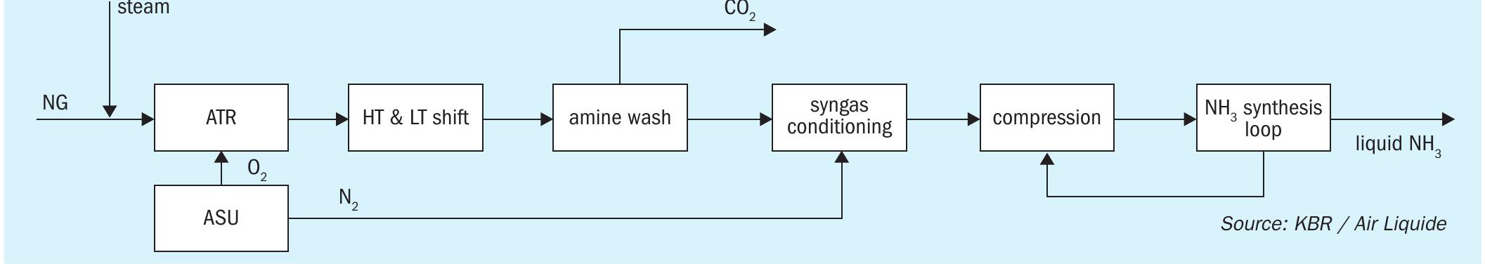
The main requirements for this project, given the location, is to maximise the energy efficiency by minimising the electricity import. Due to the remote location of the plant, the electricity available from the grid would have a high carbon intensity, worsening the “carbon impact” of the plant. Thus, decreasing the electricity import enables both a higher efficiency and lower carbon intensity. This is accomplished by an optimised integration between the compressor drives of the ammonia loop, ASU and refrigeration loop with the steam generating front-end.
Air Liquide’s experience in designing and operating both oxygen-blown reforming units and ASUs ensures a coherent and high level of safety and reliability. It also ensures that all operational cases are taken care of holistically.
Low-carbon ammonia production at scale is, most of the time, envisaged to make the supply chains economically viable, therefore, an additional merit of this set-up is that up to 10,000 t/d can be produced in one train of the ATR, ASU and NH3 synthesis loop. For very large plants, Air Liquide can supply its proprietary carbon capture technology, Recticap™ , which also enables the syngas treatment and carbon capture in one train.
KBR’s ammonia synthesis loop, proven for world-scale ammonia production with the largest ammonia converter, does not require a purge gas recovery unit, as inert-free syngas is provided from the front-end. It is thus ideally suited to reach its full potential for energy transition, when combined with large-scale low-carbon oxygen blown syngas generation.
Energy transition project at industrial location
This case is another typical example where the ammonia plant is located in an industrial location (e.g. chemical park, integrated chemical plant), being able to utilise common services and supplies. Fig. 3 shows a configuration, where the natural gas intake can be minimised and a combined/flexible production of ammonia and hydrogen is implemented, achieving lowest carbon intensity targets with renewable electricity tie-in.
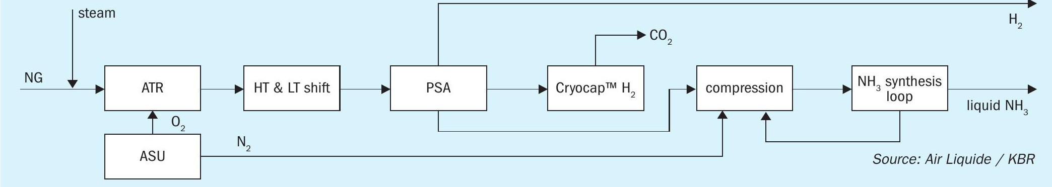
The main requirements of this set-up result from the location of the plant and the demand for minimised natural gas consumption and minimised carbon intensity. There are several process highlights of this set-up. First of all, the flexible hydrogen consumption, which can be adjusted to the customers’ daily requirements. Furthermore, any CO2 product specification can be fulfilled via Air Liquide’s Cryocap™ H2 technology: stringent CO2 purity of more than 99.99 %, as well as pressurised or liquefied CO2. As low-carbon electricity is available at these locations, the process integration focuses on the use of it in order to decrease the carbon intensity. This results in further reduction of the plant size and related capital expenditures.
Air Liquide, as a leader in industrial gas production and operator of ASUs, can potentially also support customers’ projects with the supply of oxygen and nitrogen as over-the-fence supply.
A first concrete example of the successful KBR and Air Liquide collaboration has been announced recently. Air Liquide, along with other stakeholders, have agreed to collaborate for the development of a production facility to produce more than 1.1 million tonnes per year of low-carbon ammonia in Houston, TX, USA. Air Liquide will provide technology and design for the ammonia syngas generation, including the ATR, ASU and Cryocap™ H2, and KBR will supply their renowned ammonia synthesis loop.
Conclusion
The Air Liquide and KBR collaboration offers a true one-stop shop for the full scope of low carbon ammonia with ATR – a single point of contact, all units designed in house and an integrated set of process guarantees.
MITSUBISHI HEAVY INDUSTRIES
Capex and opex evaluation of blue ammonia process configurations for higher CO2 recovery
Comprehensive economic case studies have been conducted by Mitsubishi Heavy Industries, Ltd. (MHI) to compare the capex and opex of different blue ammonia process configurations for higher CO2 recovery. At present, the hydrogen required for the commercial production of ammonia is typically derived from natural gas through steam reforming, which is highly energy intensive, requiring approximately 30 GJ of energy and around 2.4 tonne of CO2 is emitted per tonne of product ammonia.
In the ammonia process, the CO2 produced in the process stream is recovered by the CO2 removal section before the ammonia synthesis loop, therefore the main focus to reduce the carbon footprint is how to reduce the CO2 emission from flue gas in the reforming section.
In this article three different configurations of the blue ammonia process with significant high CO2 recovery (99% in ammonia plant ISBL) are discussed and compared:
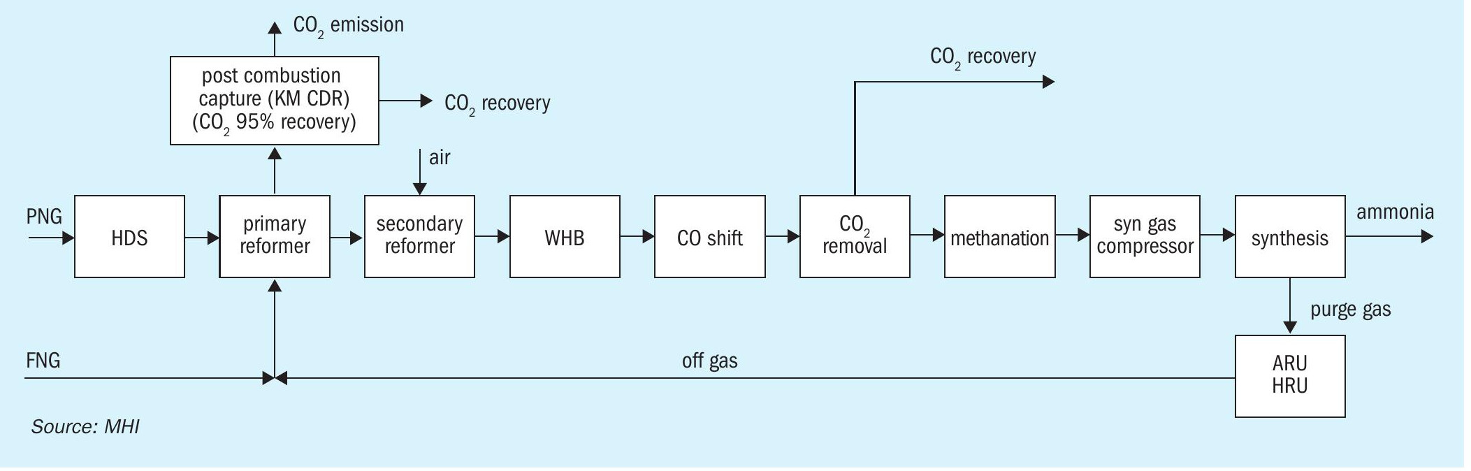
- Conventional SMR + post combustion capture (Fig. 1)
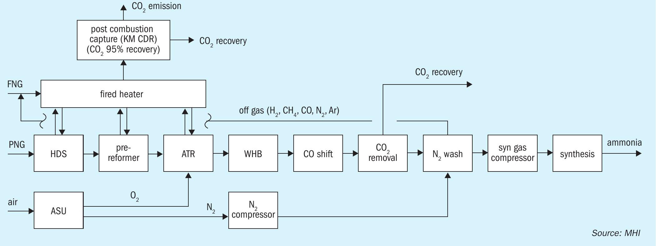
- ATR + post combustion capture (Fig. 2)
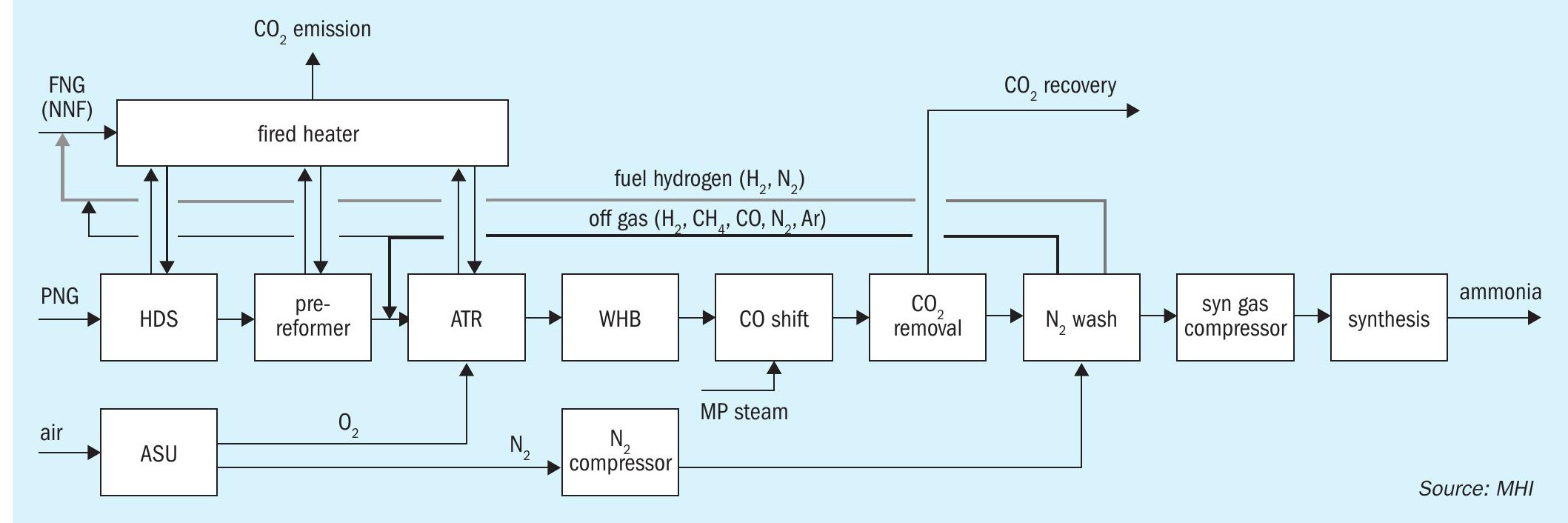
- ATR + H2 fuel combustion (Fig. 3)
The ATR process was evaluated using the TOPSOE SynCOR Ammonia™ process and the post combustion capture was evaluated using MHI’s novel Advanced KM CDR Process™
Conventional SMR process and ATR process
Reforming of natural gas in an ammonia plant can be carried out in two ways:
- conventional two-step steam-methane reforming (SMR) or
- single autothermal reforming (ATR)
In the conventional SMR process, approx. 30% of CO2 is produced by primary reformer burners to provide endothermic reforming reaction heat by fuel combustion. Therefore, base carbon capture rate by the CO2 removal section in the process stream will be approx. 70%. In recent years, modified versions of the SMR process with improved plant capacity, energy efficiency and CO2 emissions have also been applied.
In ATR, the steam reforming reaction and partial oxidation occurs simultaneously in a reactor wherein pure oxygen is fed to combust internally a fraction of the methane feed. The exothermic combustion of methane provides the heat required for the steam-methane reforming reaction. Therefore, the external heat input required for preheating the feed in the ATR process is lower than that of a conventional SMR process. As a result, approx. 85 to 88% of the CO2 generated in the ammonia process is directly captured from the process CO2 section without any special efforts.
In addition to carbon footprint, ATR has other advantages over conventional SMR in terms of plant capacity, smaller footprint and energy consumption. ATR designs such as TOPSOE’s SynCOR™ technology has been developed especially for large capacity plants e.g., with ammonia production up to 7,000 t/d NH3 . Since ATR does not require a tubular reformer, smaller plot area is possible. Moreover, the SynCOR™ reactor can operate with a lower steam-to-carbon ratio (S/C) below 1.0, typically at 0.6, compared to 2.8 to 3.0 in the conventional SMR process. Hence, energy consumption in the form of the required steam is reduced.
To further improve the CO2 recovery rate, the hydrogen fuel combustion process and post-combustion CO2 capture process can also be considered.
Hydrogen fuel combustion and post-combustion CO2 capture
In recent blue ammonia projects, the hydrogen fuel combustion process is generally considered. In the hydrogen combustion process (Fig. 3), hydrogen produced in excess of the amount required for ammonia synthesis is used as a fuel for reforming section, thereby bringing CO2 emissions from the process closer to zero. In the conventional ATR process, CH4 and CO as off-gas removed by the nitrogen wash unit are used as the main fuel source of the fired heater, while in the hydrogen combustion process, hydrogen production is increased by recycling the off-gas to the ATR inlet to realise a hydrogen fired heater. The hydrogen combustion process can achieve significant low CO2 emissions without post combustion technology. The unconverted carbon continues to circulate through the front end until it is converted to CO2 and recovered in the CO2 removal section, thereby making it possible to achieve a CO2 recovery rate of more than 99% from the ammonia process.
In the hydrogen combustion process, the flow rate through the entire front-end section is increased compared to a conventional ATR process. The higher the recovery rate required, the higher the off-gas recycle rate, thus having an impact on the opex and capex. As larger scale capacity is required for blue ammonia production as a clean fuel, the hydrogen combustion process may also be problematic in terms of equipment size in the front-end section such as the CO2 removal unit.
Instead of producing hydrogen fuel, another option to reduce the plant overall CO2 emission is to recover the CO2 from the flue gas of natural gas-fired heaters. In the post-combustion CO2 capture scheme (see Fig. 1 for SMR, Fig. 2 for ATR), the flue gas is treated to recover the CO2 using a post-combustion technology with high carbon capture rate such as MHI’s KM CDR™ . In this configuration, excess hydrogen production and off-gas recycle is not necessary. Although additional investment for the carbon dioxide recovery facility is imperative, flue gases from other emission sources such as the auxiliary boiler and gas turbine can also be treated using the same facility.
KM CDR technology
MHI’s high efficiency chemical solvent post combustion process, the KM CDR Process™ , has a proven record and knowledge based on 30+ years in-house research and development and experience. R&D started in 1990 in collaboration with Kansai Electric Power Co., Inc. (KEPCO), and in 1999 MHI delivered the first commercial plant using an advanced sterically-hindered amine-based solvent, KS-1™ in Malaysia. Since then, it has been delivered in 18 commercial plants (three under construction) including the world’s largest post combustion CO2 capture commercial plant (2016, Petra Nova, 4,776 t/d CO2 capture). Most of these commercial references are aimed at CO2 recovery from the ammonia plant reformer for enhanced urea production.
The KM CDR Process™ consists of three main sections:
- the flue gas cooler,
- the absorber (for CO2 recovery)
- the stripper (for solvent regeneration).
Key technical feature of the technology are listed below:
- flexible CO2 capture rate (90% to 98% or higher depending on the carbon intensity requirement);
- compatible with multiple flue gas sources;
- good dispatchability including emergency scenario based on dynamic simulation (no impact on the reformer operation by unexpected trip of CO2 capture plant;
- flexible CO2 product pressure from regenerator;
- various options for amine emission recovery system to meet specific project requirement, e.g., multiple washing stage, acid washing, and others;
- Applicable to existing facilities as a retrofit to enhance urea production or to reduce the CO2 emission from the existing facility for blue ammonia.
Recent update – Advanced KM CDR Process™
With the need for CO2 capture growing around the world, MHI has developed the Advanced KM CDR Process™ , which uses a new solvent KS-21™ , a technologically improved version of the former KS-1™ solvent.
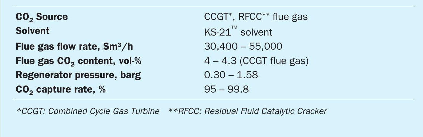
A demonstration test of the new process has been completed at the Technology Center Mongstad (TCM) in Norway using exhaust gas from gas turbine as a CO2 source. KS-21™ offers superior regeneration efficiency compared to the conventional solvent. In addition, the economic efficiency is further improved by reducing operating costs due to its low volatility and high stability against deterioration. The solvent consumption is more than 20% lower than that of KS-1™ , depending on the conditions due to the suppression of thermal degradation of the solvent. It is also possible to increase the operating pressure of the regenerator, which can reduce the power of the CO2 compressor by 10~15%, since the solvent can withstand higher temperature.
In the demonstration test at TCM, the new solvent greatly outperformed the conventional amine solvent (MEA) and also outperformed MHI’s existing KS-1™ solvent. Major conditions and results of the TCM demonstration test are summarised in Table 1.
Economic case studies
Comprehensive economic case studies were conducted for a low carbon blue ammonia plant with natural gas as a feedstock. In this study, more than 95% of the CO2 recovery rate in the ammonia plant inside battery limit (ISBL) is considered in all cases. For post combustion recovery, the Advanced KM CDR Process™ is applied as ISBL. For all cases, the required utilities and offsite facilities (such as the air separation unit, power generation, CO2 compression / dehydration, auxiliary boiler, cooling water, etc.) are taken into consideration in the evaluation.
Electric power for normal operation is fully generated by the steam turbine generator in the plant, allowing the cost and/ or carbon intensity of the import power to be ignored, to compare each case by minimum variables. River water is assumed as a water source and is treated by the water treatment unit to fulfil the quality requirement in each service. The ammonia storage tank and ammonia ship loading facility is also considered in the plant. Recovered CO2 is compressed and dehydrated to fulfil the CO2 pipeline requirement.
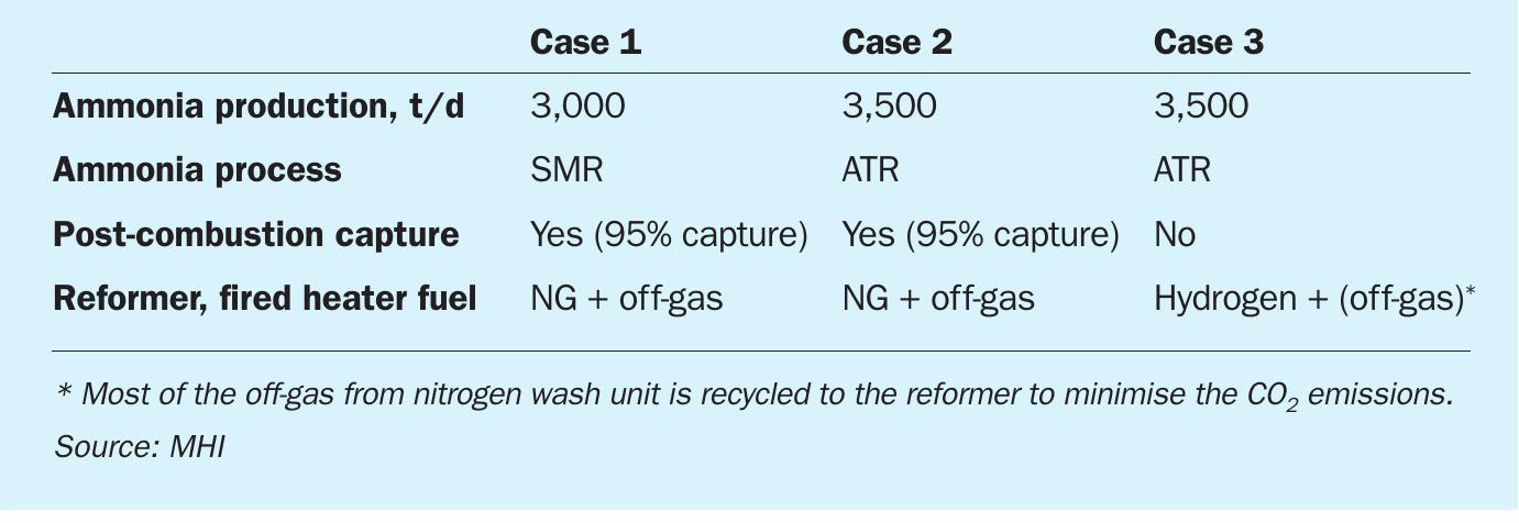
Case studies
The three cases considered were:
- Case 1: 3,000 t/d of ammonia, conventional SMR + Advanced KM CDR Process™ (post combustion capture from primary reformer flue gas).
- Case 2: 3,500 t/d of ammonia, ATR + Advanced KM CDR Process™ (post combustion capture from fired heater flue gas).
- Case 3: 3,500 t/d of ammonia, ATR + hydrogen combustion (internal off-gas recycle to improve the CO2 recovery).
In Case 1, the conventional two-step reforming process (SMR + air fired ATR) is applied in combination with the Advanced KM CDR Process™ (see Fig. 1). 95% of the CO2 in the primary reformer flue gas is recovered by the KM CDR unit. The overall CO2 recovery rate in the ammonia plant ISBL is more than 95% in consideration of process CO2 removal unit.
In Case 2, the Topsoe SynCOR Ammonia™ process is applied in combination with the Advanced KM CDR Process™ (see Fig. 2). 95% of the CO2 in the fired heater flue gas is recovered by the KM CDR unit. The overall CO2 recovery rate in the ammonia plant ISBL is more than 99% in consideration of process CO2 removal unit.
In Case 3, the Topsoe SynCOR Ammonia™ process is applied (see Fig. 3). The produced hydrogen (and nitrogen) is extracted from the nitrogen wash unit and used as a fuel for the fired heater. The nitrogen wash unit off-gas is recycled to the ATR to avoid CO2 emissions due to carbon (CH4 and CO) combustion. The overall CO2 recovery rate inside battery limits is more than 99% which is achieved by pre-combustion capture only. Part of the nitrogen wash unit off-gas is used as fired heater fuel to avoid the accumulation of inerts. Due to the off-gas recycle, the front-end capacity is larger than Case 2 to produce hydrogen fuel.
A summary of the case comparison is shown in Table 2 and the summary of CO2 recovery rate is summarised in Table 3.
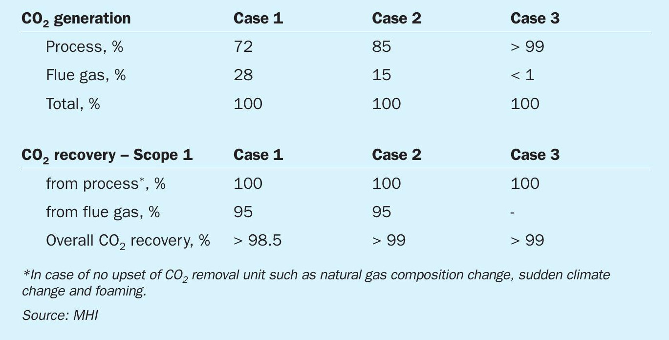
In this study, carbon recovery is discussed for Scope 1, however, it is also possible to achieve more than 95% CO2 recovery for Scope 1+2 using KM CDR technology to treat flue gas from the auxiliary boiler and/ or gas turbine generators without renewable energy. In such case, further capex benefit is expected since the KM CDR unit can treat several flue gases in one unit.
Results and discussion
Table 4 compares the operating and capital expenses based on the defined cases. The results show that Case 2 (ATR + post combustion capture) can achieve the lowest opex and capex. For smaller ammonia plant capacity, Case 1 (SMR + post combustion capture) will have the lowest capex. For Case 3 (ATR + H2 fuel), both opex and capex is slightly higher than Case 2. Although Case 2 requires a post combustion capture plant to recover the CO2 from the fired heater flue gas, Case 3 requires larger front-end equipment and more feedstock due to the production of fuel hydrogen. The power consumption for the ATR process is higher due to the heavy duty equipment such as the air separation unit, but total opex is lower than the SMR process. The results are based on 99% CO2 capture in an ammonia plant ISBL, the optimal process configuration in terms of opex and capex will vary depending on the required CO2 recovery and plant capacity. If the required CO2 recovery rate is 85~90%, the hydrogen fired process would be competitive compared to the ATR + post combustion capture configuration since the impact on front-end capacity is small.
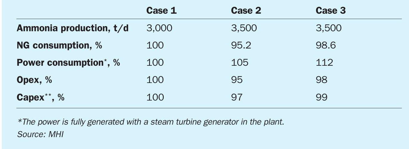
Table 5 shows a qualitative evaluation for each case. Case 3 has an advantage in terms of plant operability since it has no KM CDR unit. On the other hand, Case 1 and Case 2 have the advantage of a common post combustion CO2 capture unit for not only reformer flue gas but also boiler and GTCC flue gas.
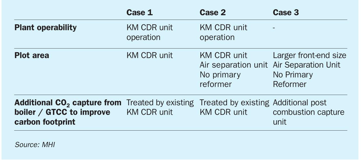
ATR with hydrogen recycle (Case 3) is often selected for new blue ammonia studies to reduce CO2 emissions for reasons such as operability, but the above results shows that ATR + a post combustion scheme (Case 2) also has a competitive edge in terms of both of opex and capex for blue ammonia. The post combustion plant will be more competitive in cases where the boiler or power-generating plant is constructed together with the ammonia plant, since the post combustion capture plant (e.g., the KM CDR Process™ ) can treat all flue gases from the ammonia plant, boiler, and power generation plant in one unit. The post combustion capture unit can be individually operated with the ammonia plant easily and is also suitable for revamp projects.
CASALE
Casale blue ammonia processes
Casale has embraced the energy transition challenge focusing on developing sustainable technologies for the production of various base chemicals, including blue ammonia from natural gas resources.
Casale’s technology portfolio for blue ammonia production includes:
- HyPURE-N
- N-ELEVA BLUE
HyPURE-N
Hypure-N is a blue ammonia process designed for large scale production (from 3,500 t/d and above in a single train) with very low carbon intensity. Virtually all of the CO2 generated in the front-end is captured and compressed, up to e.g., 200 bar g, for sequestration or other utilisation purposes, e.g., for enhanced oil recovery. CO2 recovery as high as 99% can be achieved.
High level of decarbonisation is achieved through the adoption of a pre-reformer and pure O2 -blown auto-thermal reforming (ATR) front-end, operated at high pressure and with a low steam to carbon ratio.
This patented reforming scheme is key to obtaining large capacities and high energy efficiency, whilst reducing the generation of high temperature heat (limited only to preheating purpose), which is the main cause of the high carbon emissions through the stack in traditional “grey” processes.
The syngas generated in the reforming section is processed in a CO shift unit, made up of Casale Axial-Radial® high temperature shift (HTS) and low temperature shift (LTS) converters, and then purified in two steps: first in an amine-based CO2 removal section and then in a liquid nitrogen wash section (see Fig. 1).
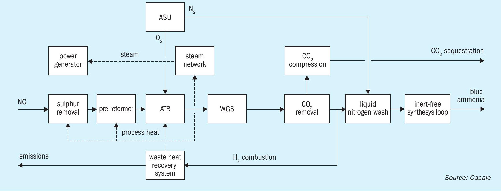
The inert-free make-up gas so obtained is compressed before being sent to a Haber-Bosh based ammonia synthesis loop where low-carbon, cold ammonia is produced.
With the exception of the syngas and the refrigeration compressors, which are driven by steam turbines, all other movers utilise electrical power generated within the plant. The process is based on a specific pre-combustion philosophy whereby all fuel requirements are met by utilising part of the carbon-free syngas generated plus other off-gases. As a result, the natural gas requirement is reduced along with the associated CO2 emissions generated from the burning of natural gas, which is central to meet the low environmental impact target.
The process is extremely flexible and may be tailored to specific needs in terms of carbon capture requirements and energy consumption.
Key benefits include:
- low energy consumption – as low as 7.4-7.6 Gcal/tonne LHV basis, including utilities and final CO2 compression at battery limits;
- reduced levelised cost of ammonia (LCOA);
- potentially no steam/power import or export required;
- total CO2 emissions per tonne of ammonia produced – from 0.08 to 0.02 t.
N-ELEVA BLUE
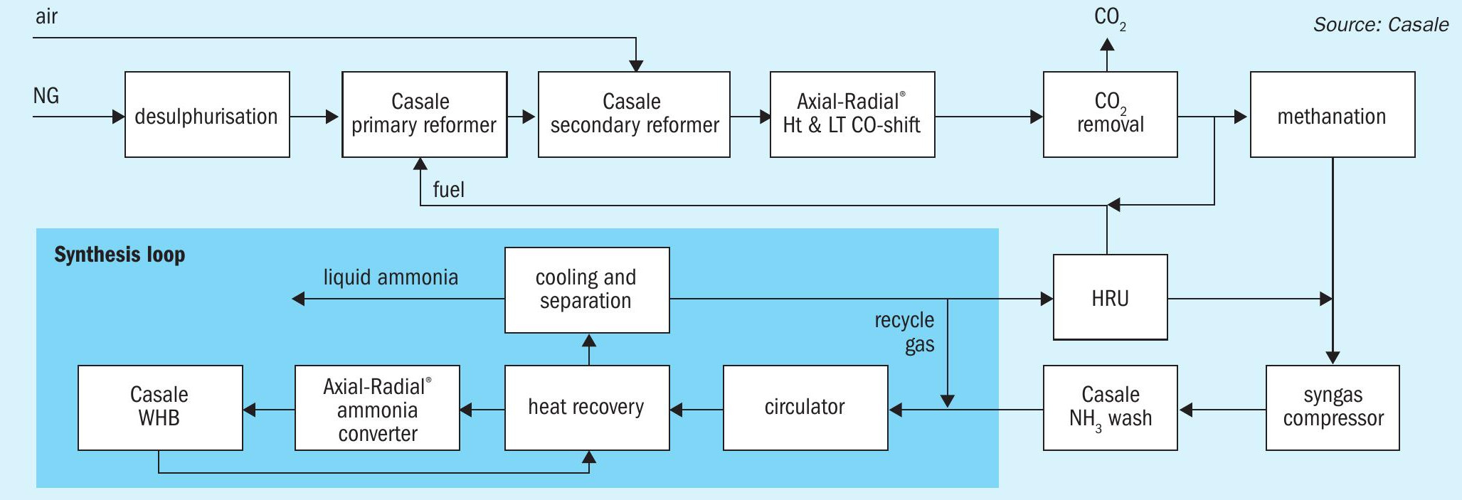
Casale also offers another process, named N-ELEVA BLUE, for the production of blue ammonia, best suited for capacities ranging from 1,000 t/d to 3,500 t/d. The N-ELEVA BLUE process is based on a conventional SMR ammonia plant with fuel gas supplied from the low carbon syngas available downstream of the CO2 removal section.
A block flow diagram of the N-ELEVA BLUE process is shown in Fig. 2.
Synthesis gas preparation
Desulphurisation: The natural gas is first desulphurised over a conventional cobalt-molybdenum based catalyst followed by absorption over a ZnO bed.
Steam reforming: After mixing with steam and being preheated, the desulphurised gas passes through the catalyst tubes of the primary reformer furnace, where it reacts to form hydrogen and carbon oxides. The fuel for the reforming furnace is mainly natural gas; the combustion air is preheated in the reformer flue gas heat recovery train (convection section).
Secondary reforming: The reforming process is completed in a catalytic reactor using the heat generated by the partial combustion of the incompletely reformed process gas from the primary reformer, using process air introduced through a special patented Casale burner. The air flow rate is adjusted to obtain the correct amount of nitrogen to achieve a 3:1 H2/N2 ratio in the final synthesis gas mixture, before it is admitted to the ammonia synthesis section.
CO shift section: After cooling to an appropriate temperature in a waste heat boiler generating high-pressure steam, the bulk of the carbon monoxide (CO) content of the raw synthesis gas is converted to CO2 and H2 by reaction with steam in a two-stage process (high temperature and low temperature shift). Casale Axial-Radial® flow internals are used in both shift reactors. A VPSA can be optionally used to enrich the air going to the secondary reformer.
CO2 removal: After cooling and condensation of the surplus steam, the gas next passes into the absorption column of a high efficiency regenerative CO2 removal system (third-party solution technology), leaving with a CO2 content of <1,000 ppmv. The CO2 is recovered from the rich solution in the regenerator of the CO2 removal system and made available for other uses. For special applications Casale can supply proprietary hardware for this section.
Methanation: Downstream of the CO2 removal section, part of the syngas (CO2 depleted) is routed to the primary reformer fuel gas system. The process gas is then reheated before undergoing a final purification stage (catalytic methanation) where any remaining carbon oxides are converted back to methane by reaction with hydrogen. The final synthesis gas is cooled and fed to the ammonia synthesis section.
Ammonia synthesis and separation
Compression: The fresh make up gas (MUG) is compressed in a centrifugal compressor up to the required pressure for ammonia synthesis. The compressor has a low pressure (LP) casing and a high pressure (HP) casing. Upon leaving the LP casing the gas is dried by washing with liquid ammonia using a Casale proprietary ammonia scrubber. This removes the last few traces of oxygenates (mainly CO2 and H2 O), which are a poison for the synthesis catalyst.
Part of the hydrogen recovered in the loop purge gas hydrogen recovery unit (HRU) is added to the MUG at this stage, whilst the remainder is added at the suction of the compressor. The dry synthesis gas flows directly to the suction of the HP casing and is compressed to the synthesis loop pressure. Ammonia synthesis: Before entering the ammonia converter, the combined makeup gas and recycle gas stream from the circulator is fed to the hot gas-gas heat exchangers, in which it is heated by hotter gas returning from the converter. The preheated gas then enters the ammonia converter, where it reacts over an iron-based ammonia synthesis catalyst.
The ammonia converter is the well proven Casale Axial-Radial® design incorporating three adiabatic, beds, with intermediate cooling by two inter-bed heat exchangers. At the converter outlet, the product gas is cooled, first in a waste heat boiler and then in the hot gas-gas heat exchangers, before condensing the ammonia produced, first in a water cooler, then in the “cold” gas-gas exchanger and lastly in the ammonia chillers.
Ammonia refrigeration: The ammonia refrigeration section mainly consists of a multi-stage compressor. The ammonia vapours leaving the last stage discharge is condensed by cooling and expansion and is collected in the refrigerant receiver.
Purge gas treatment
Ammonia recovery: To prevent excessive build-up of inerts in the synloop, a portion of the recycle gas is continuously withdrawn as “purge gas”. Along with other inert gas from the refrigerant ammonia receiver, this gas is washed with water in two separate packed columns to absorb its residual ammonia content.
Hydrogen recovery: The washed purge gas is processed in a hydrogen recovery (HRU) unit, which removes most of the hydrogen it contains for it to be returned to the synthesis loop.
Process benefits
Key benefits include:
- low energy consumption (from 7.9 Gcal/ tonne LHV basis);
- reduced capex;
- the steam export can be adjust according to specific needs, from nil export to maximum export;
- compact and simple lay-out, with all sections arranged in a way to minimise the overall footprint and optimise the connections across the different sections of the plant.
The total CO2 emissions to the atmosphere per tonne of ammonia produced are up to 0.1-0.15 t.
——————————————————————————————————————————————
JOHNSON MATTHEY
Low carbon intensity ammonia using JM’s LCH technology to deliver net zero targets
Ammonia production is a highly energy-intensive process, which currently accounts for about 2% of global energy consumption with commensurate CO2 emissions. The challenge facing the ammonia industry is twofold – how to increase overall ammonia production without increasing overall CO2 emissions; and how to decrease the CO2 intensity of existing ammonia manufacturing assets.
Johnson Matthey’s (JM’s) LCH technology is an effective way of decarbonising an ammonia flowsheet which offers:
- high feedstock efficiency;
- enables use of power from renewable sources;
- higher CO2 capture rate;
- proven, reliable and safe technology;
- enhanced feedstock flexibility.
In conceptual terms, an ammonia manufacturing process consists of a hydrogen production step followed by a synthesis step in which hydrogen reacts with nitrogen to make ammonia.
As most CO2 emissions are associated with the hydrogen production step, decarbonised hydrogen production is a prerequisite to decarbonised ammonia production.
When low carbon hydrogen is produced more CO2 is captured as there is far less atmospheric combustion.
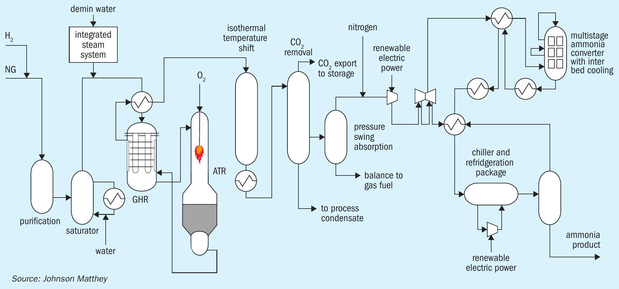
Many ammonia projects are in areas with increasingly abundant renewable energy resources. Consequently, it is no longer necessary to constrain the design of an ammonia plant to generate sufficient steam to provide all the motive power required to drive the main compressors. Instead, ammonia plants can be designed and optimised around renewable power import, as illustrated in Fig. 1.
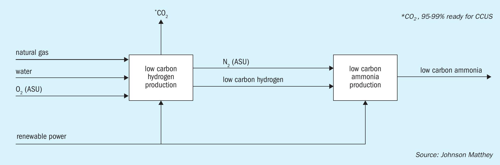
The benefits from this approach include:
- lower carbon intensity;
- lower specific gas consumption;
- lower capital cost.
Johnson Matthey LCH technology
Advanced gas reforming is the principal technology used for blue hydrogen production. It consists of either an autothermal reformer (ATR) or an ATR coupled with a gas heated reformer (GHR).
LCH technology with ATR
The ATR combines two processes that take place in a primary reformer:
- heating of the process gas (on the air side of the tubes in a SMR);
- reforming of the feedstock (on the process side of the tube in a SMR).
The ATR carries out both these functions on the process side of the flowsheet. It does this by introducing oxygen through a burner, which entrains the oxygen flow with the process gas flow. This happens in the area below the burner. Simultaneously the gas stream ignites due to the flammability of the gas mixture, and it is partially oxidised (burnt) creating heat, resulting in the formation of CO and H2 O. These processes take place in the neck of the JM ATR design.
The hot, well mixed gas stream then passes through a catalyst bed, where the reforming reactions take place, producing hydrogen by reacting process gas with steam as shown by the general reaction equation below:
CH4 + H2O = CO + 3H2
CO also reacts with H2 O in the process, to produce H2 , and CO2 via the water gas shift process.
Due to the elevated temperature (typically 950 to 1,050°C exit the ATR), the equilibrium position favours high methane conversion, and the kinetics to reach the equilibrium point are elevated. Therefore, when using an active catalyst with properties that protect it from the harsh process conditions, long lives and high effectiveness can be gained from relatively small volumes of catalyst.
The JM LCH technology with ATR flowsheet (Fig. 2) may be integrated with an ammonia synthesis loop in an analogous way to what we know today, that uses high grade steam exit the secondary reformer. The ATR flowsheet uses the involuntary steam raised from the reform gas boiler(s), exit the ATR, to provide motive steam.
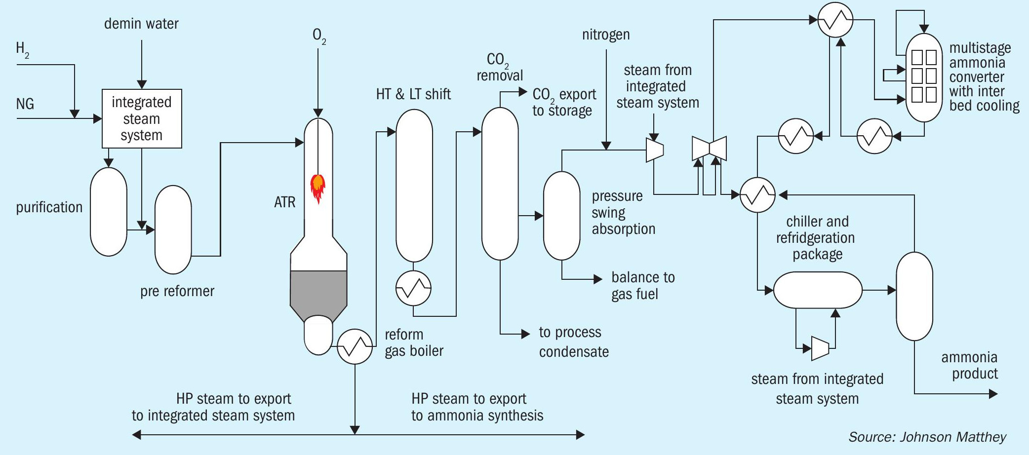
The LCH technology flowsheet provides a low level of methane slip exit the ATR and uses a PSA to remove trace CO slip from the WGS section. The hydrogen product has a low inert level and the nitrogen also has high purity because it is a product of the air separation unit (ASU), not an air intake as is typically used today. This means there are less inert gases built up in the loop, lowering the purge, so elevating the effectiveness of the loop. This has operational cost benefits and means the capex is lower for a given production capacity because equipment is smaller.
LCH technology with GHR / ATR:
Having just described a LCH technology with an ATR that provides involuntary steam raising, we now review a flowsheet that can be integrated to provide low steam export from the hydrogen production process. This enables the use of external renewable electrical power. This can lower the carbon intensity of the product an lower the cost of the production as less natural gas is needed per unit of ammonia production.
This configuration uses the heat exit the ATR to directly drive the reforming reaction in a GHR (see Fig. 3), where the GHR replaces the reformed gas boiler in the ATR flowsheet, using the high-grade heat on the shell side of the GHR, to drive approximately 30% of the total hydrocarbon reforming reaction, on the tube side, before the gas enters the ATR. This JM technology is recognised for leading the way in making best use of the available sensible heat.
The ATR then completes the remaining 70% of the reforming reaction, through the processes already described. In this case the size of the ATR, for the same hydrogen production, can be smaller. It follows that the ASU can also be smaller, as less oxygen is required. This has two effects:
- it lowers operational costs, as less power is needed for the ASU. Instead, there is direct use of the high-grade heat from the ATR;
- it is capex neutral, as the GHR adds a unit operation, while the ASU is smaller and lower in cost.
Other benefits of an GHR/ATR flowsheet are:
- the natural gas requirement per unit of hydrogen (and so ammonia) is reduced by typically 15%, as no gas is used to raise steam;
- it follows the CO2 production is also reduced proportionally by the same amount;
- as future import power decarbonises, the LCH flowsheet is future proofed in that it will immediately be able to take advantage of green power while making hydrogen with maximum feed gas efficiency.
The benefits from the high purity gases supplied to the ammonia loop are still provided. These advantages are fundamental traits of LCH technology flowsheets.
Two cases have been descibed – one where a LCH technology flowsheet provides of the steam requirement by integrating LCH technology with an ATR flowsheet with an ammonia loop; the other where the steam demand is substituted with electrical power, and there is minimal steam generation from the hydrogen section of the LCH flowsheet with GHR/ATR. This small amount of steam is combined with steam raised from the ammonia loop and can be used to offset the import of OSBL (outside battery limits) power through driving a turbine. It follows optimisation to import renewable power and does not necessitate elimination of all steam turbines. JM’s LCH technology is flexible so can be optimised on a project specific basis according to metrics such as:
- gas availability and cost;
- electrical power availability, cost and CO2 credentials;
- carbon intensity requirement of product ammonia.
References for LCH technology
The LCH technology is a combination of mature, well proven unit operations which are already utilised in other JM technologies and when effectively integrated can produce low carbon hydrogen and ammonia at a large scale.
Examples from integrating LCH technology with an ammonia loop
JM have modelled the LCH technology schemes shown in Figs 2 and 3.
The scenario illustrated in Fig. 2 shows the ATR flowsheet, integrating the high pressure (HP) steam raised in the reformed gas boiler, downstream of the ATR, and that from the heat recovery in the ammonia loop to provide the motive power to the loop.
The scenario illustrated in Fig. 3 shows the GHR/ATR flowsheet, this generates electric power from the steam raised which is predominately from the ammonia loop. This is combined with outside battery limits (OSBL) power to meet the motive power demands of the loop. This electric scheme means there is no shared HP steam system, so should be considered where flexibility is required between hydrogen:ammonia production, as it does not necessitate ammonia production to close the energy balance. It is also the flowsheet most advantaged to benefit from increasingly available renewable power.
The ASU and CO2 removal may be steam or electrically driven and is a flexibility in either design. In each case the designs have been developed to provide the same ammonia capacity and carbon capture rate, in this case 97%. It is important to note that the carbon capture rate can be tuned, if a higher (or indeed a lower) value is needed.
The efficiency of the power plant increasing and how this would favourably affect the overall energy efficiency of the blue ammonia process was also considered.
Differences to be considered when making comparisons between low carbon ammonia flowsheets (making ”blue” ammonia) and current non-decarbonised SMR flowsheets (making “grey” ammonia) are:
- Low carbon technology captures more CO2, so energy demands on the CO2 capture system are higher than an SMR flowsheet, where about 70% of the CO2 reaches the CO2 removal system. This adds to the energy demand, as >95% of the CO2 reaches the CO2 removal system and is captured.
- CO2 compression also adds to the energy demand of low carbon technology to facilitate storage.
Therefore, it is to be expected that the energy demand per tonne of low carbon ammonia is higher than that of grey ammonia. Assessments of this energy penalty are of the order of 10%.
Considering the impact of electrical power plant efficiency, both LCH technology flowsheets see some benefit from this change, as both flowsheets use some electric drives, for example the ASU package. Nevertheless, as the grid changes, flowsheets that make least steam and use electric power instead would be most advantaged, as power plant efficiency increases.
Improvements in power generation efficiency leads to improvements in the efficiency of plants which consume electric power. This improvement can offset the blue ammonia energy penalty referred to above.
The wider energy ecosystem will change over the depreciation period for plants built today.
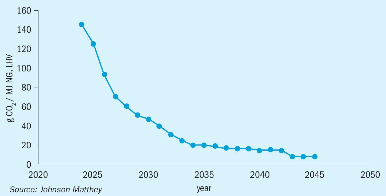
The carbon intensity of the electricity will reduce, as renewable power becomes increasingly available. This will reduce the carbon intensity of the ammonia product.
Fig. 4 shows the reduction of scope 2 emissions projected by the UK for electical power feed into the grid.
Traditionally ammonia plant efficiencies have been calculated using the assumption that electrical energy consumed is produced from marginal natural gas. A conversion factor of 40% is often used for this conversion efficiency. As power grids become increasingly based on renewables, this dependency is less relevant; for example, a fully renewable grid offers an efficiency loss that approaches zero.
Considering the total carbon intensity, not just direct emission from production, is part of most standards being put in place, this means everything within the emissions system boundary must be considered, including the gas, electric and water supply.
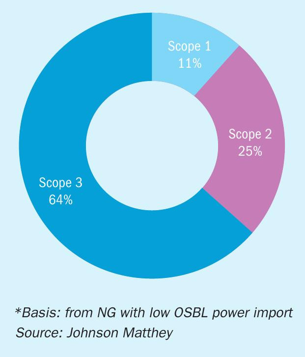
Analysis of the total carbon intensity of the flowsheets based on 2024 carbon intensity data shows how scope 1 emission values (i.e. direct emissions, a company causes by operating the things it owns or controls) are the smallest factor, and the dominate factors are from the import of the gas and electricity (see Fig. 5).
The UK low carbon hydrogen standard is <2.4 kg CO2 per kg H2. This, the most stringent global standard today, can be translated to a value for NH3, based on the weight percentage H2 in NH3. This results in a value of <0.42 kg CO2 per kg NH3.
Considering the total CO2 emitted from the natural gas processed and the electrical power, both LCH flowsheets offer a carbon intensity below the translated total value of 0.42 kg CO2 per kg NH3. However, over time the flowsheet with the lowest carbon intensity will change as the relative carbon intensity of gas and electric power change.
The data in Fig. 6 shows the decreasing carbon intensity trends for both flowsheets.
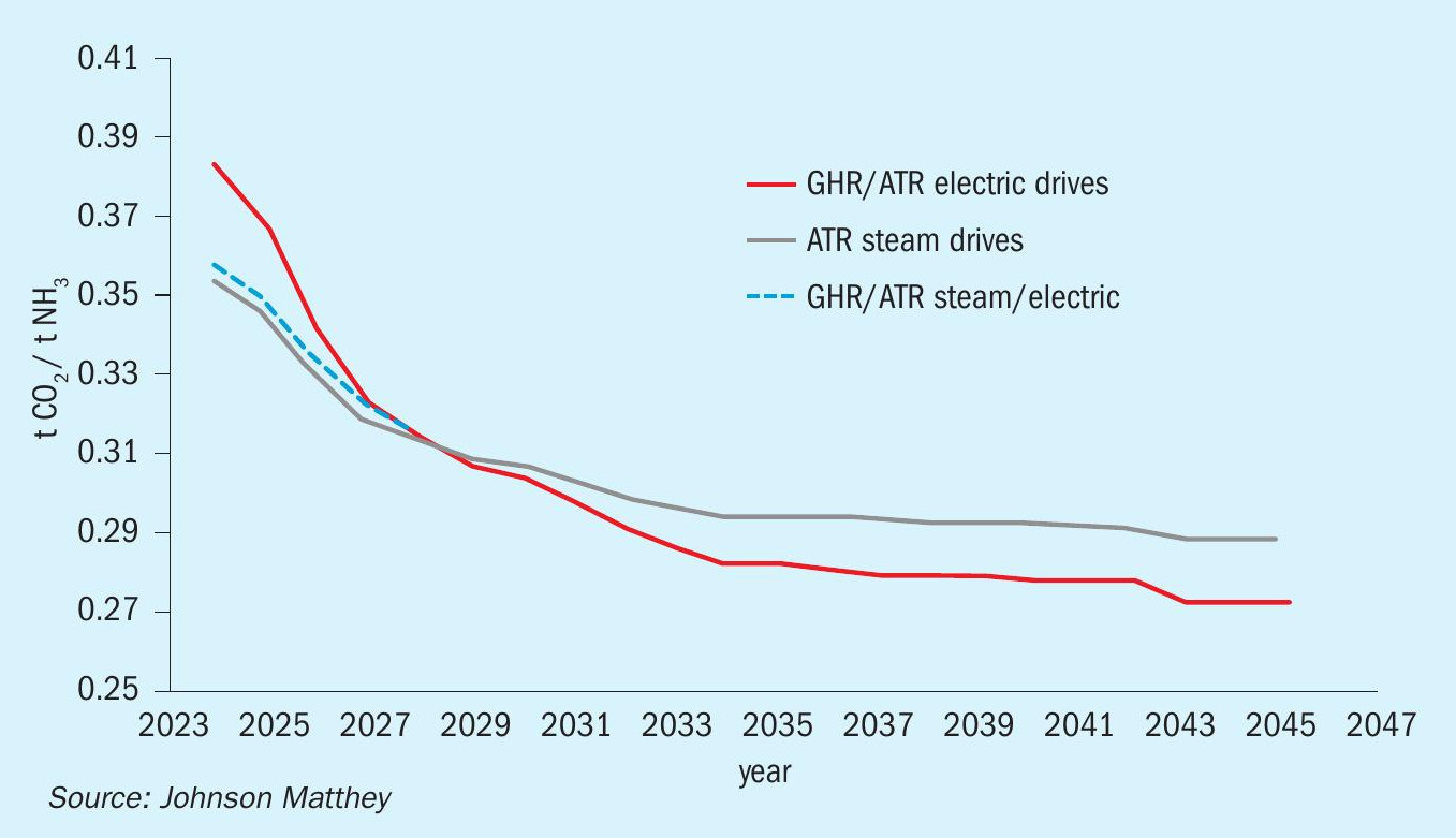
Today a flowsheet utilising steam raised from natural gas has the lowest carbon intensity value, so the focus would currently be to consume as little gas as possible to achieve this. Over time, electrical drives offer the lowest carbon intensity option. This should not be surprising as this flowsheet allows the operator to access increasingly low carbon intensity OSBL power.
The dotted line illustrates that although two extremes have been selected, dominated by steam or electric, there is the option to design a flowsheet to use a mix of steam and electricity and create an optimum for an individual project. Either flowsheet can the optimised to maximise the value based on the cost and availability of gas and electricity and the overall carbon intensity to provide the optimal solution.
Conclusion
LCH technology (both with ATR or GHR/ ATR) meets low carbon hydrogen criteria. It de-risks the transition to low carbon ammonia production as each unit operation is industrially proven. Which LCH technology flowsheet offers the best solution largely depends on the energy situation, and the availability of low carbon intensity electrical power.
In the near term the lowest carbon intensity flowsheet might be steam driven but in the medium to long term the GHR/ ATR flowsheet is the lowest carbon intensity solution as it:
- maximises the use of high-grade heat
- reduces the amount of gas needed to produce ammonia;
- allows operators to access renewable power to further lower the carbon intensity of their product.