Sulphur 411 Mar-Apr 2024

31 March 2024
Ultra capacity with ultra low emissions
CLAUS TAIL GAS TREATING
Ultra capacity with ultra low emissions
As environmental SO2 emission regulations become more stringent, tail gas treating options become limited. To potentially achieve lower opex and improved plot plan, utilising a biological desulphurisation process as an alternative to a conventional amine-based TGT unit is becoming of increased interest in the oil and gas industry. At the same time, demands for increased SRU capacity and reliability favour the use of medium and high-level oxygen enrichment.
Fluor recently evaluated revamp options for an existing refinery with air operated 3 x 100 t/d SRUs to improve its sulphur removal efficiency to meet more stringent emission specifications.
The primary project objectives were:
- achieve an environmental emission specification below 300 mg SO2 /Nm3 (thermal oxidiser stack SO2 emissions limit of 100 ppmv, dry at 2% excess O2 );
- increase each train capacity to 150 t/d sulphur;
- optimise capex and opex;
- optimise plot space;
- optimise flexibility in operating window;
- enhance sulphur recovery efficiency and on-stream time;
- enhance client image as an environmentally friendly company;
- reduce carbon footprint by mitigating the need for building new SRU units;
- handle some sour gas streams with unfavourable H2S/CO2 ratios.
The existing site uses SUPERCLAUS® tail gas treating (TGT). As with many sites using a solely catalyst-based method for sulphur recovery (SUPERCLAUS® , EUROCLAUS® , or simply three-stage Claus configuration), the existing system can no longer meet the increasingly stringent environmental SO2 emission regulations.
Two tail gas treating options proven for high sulphur removal efficiency (SRE) were considered:
- hydrogenation followed by amine treatment using a specialty MDEA;
- hydrogenation followed by the biological desulphurisation process Thiopaq O&G (TOG).
The amine TGT process is well known, capable of achieving high SRE and flexible to capacity variations between air-based and oxygen-enrichment operation. However, the client wished to search for alternative systems, considering that amine TGT systems have relatively high capex, plot space requirements and high steam consumption. With the goal to achieve lower opex and smaller plot space, an option utilising a biological desulphurisation process as an alternative to a conventional amine-based TGT unit is becoming of increased interest in the oil and gas industry during this energy transition era.
TOG and TOG ULTRA bio-desulphurisation technologies developed by Paqell, can comfortably achieve an H2S treated gas specification of <25 ppmv in low pressure units.
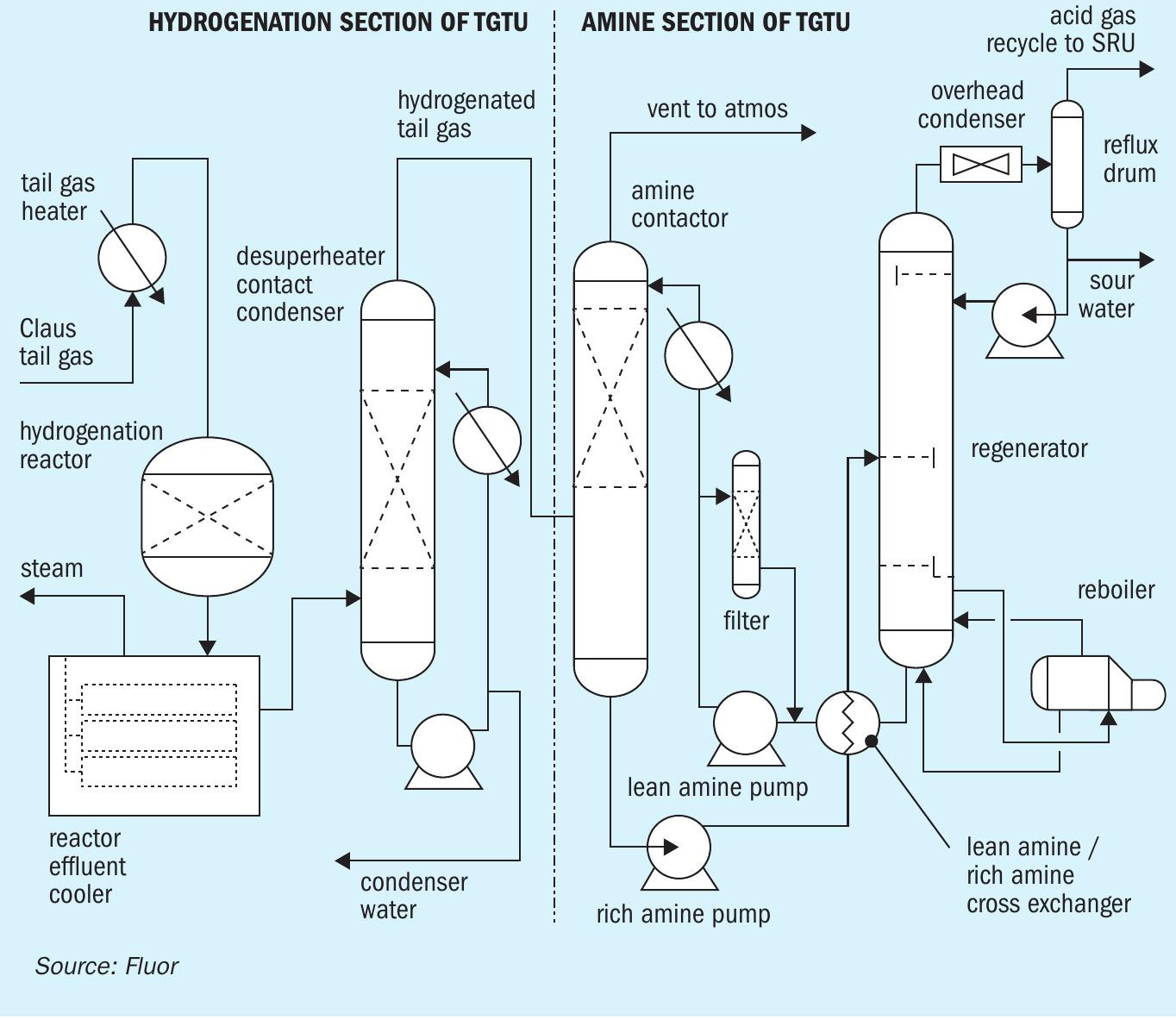
Common hydrogenation section
Fig. 1 shows the major equipment items in the common hydrogenation section, which is identical for both amine and TOG systems, and the amine TGT section. For this project tail gas leaving each SRU Claus train is routed to a dedicated tail gas heater. Tail gas enters with an H2S/SO2 ratio of between 2 to 4; for optimal Claus sulphur recovery efficiency this ratio is controlled at 2 in the upstream Claus train.
The hydrogenation process catalytically reduces sulphur compounds and elemental sulphur vapour in the Claus tail gas to H2S, which is subsequently removed in the downstream TOG absorber or amine contactor.
Hydrogenation and hydrolysis reactions for the four primary sulphur constituents are as follows:
S + H2 -> H2S (1)
SO2 + 3H2 -> H2 + 2H2 O (2)
CS2 + 2H2O = 2H2S + CO2 (3)
COS + H2O = H2S + CO2 (4)
Process gas is heated in an indirect tail gas heater using HP Steam, prior to introduction into the hydrogenation reactor. Carbon monoxide in the Claus tail gas reacts with water in the hydrogenation reactor to make hydrogen and CO2 . Often, the Claus tail gas has sufficient H2 and CO for hydrogenation of the sulphur compounds in the tail gas for normal operation with no consumption or a small consumption of externally-supplied hydrogen.
There is a temperature rise across the hydrogenation reactor due to the exothermic reactions. A reactor effluent cooler removes some heat from the reactor effluent by generating LP steam on the shell-side. The process gas leaving the reactor effluent cooler is still superheated.
Desuperheater contact condenser
The reactor effluent will be further cooled to a temperature suitable for amine or TOG performance (about 35°C) in a desuperheater contact condenser (DCC) column. The process gas has less capacity to retain water as it is cooled, so the excess water will be removed. This has the benefit of reducing the volumetric flow rate of the cooled process gas.
In a single bed design, the reactor cooler effluent enters the bottom of a packed bed, where it is cooled, and water vapour is condensed by counter-current direct contact with cooled circulating water in a bed of random packing. Water is circulated by the contact condenser pump, which draws liquid from the chimney tray below the top packed section. The circulating water is cooled in the forced draft contact condenser air cooler (not pictured in Fig. 1) and contact condenser trim cooler (by heat exchange against plant cooling water) and returned to the column above the packed bed on flow control.
A single bed DCC design requires stainless steel material to reduce corrosion rates, in case of condensing sulphuric acid, which may occur especially during a major SO2 breakthrough event. Also facilities for either ammonia or caustic injection are required in case of undesired SO2 breakthrough from the upstream hydrogenation reactor.
If SO2 breakthrough is not mitigated in the DCC, SO2 will enter the downstream amine TGT system for that option, where degradation of the circulating amine solvent may occur. There have been incidents where the entire inventory of circulating amine solvent needed to be replaced because the degraded solution can no longer perform sufficiently. Poor H2S removal in the amine contactor leads to inability to meet the stack SO2 emission specifications.
In Fluor’s proprietary two-bed DCC design, the upper bed serves the same function, namely contact condensing. However, there is also a lower bed, where the superheated reactor effluent enters and is contacted counter-currently against a circulating buffered weak caustic solution. In this manner, some caustic is available at all times to mitigate against SO2 breakthrough.
Some systems implement ammonia injection based on pH after an SO2 breakthrough event has occurred to reduce corrosion, but in these ammonia-injection systems, some SO2 may have already slipped to the downstream amine system. Caustic systems that only inject caustic based on pH similarly have this issue, namely that some SO2 may have already slipped to the downstream amine system.
Configuration
For this project, separate trains are included through the hydrogenation section for greater reliability. With the use of Fluor’s proprietary two-bed DCC design, the risk of SO2 breakthrough slipping into the downstream amine system is mitigated. However, per the client’s decision, because of the remote possibility of a major SO2 breakthrough event degrading the entire inventory, or a significant portion of the circulating amine solvent, there are also three separate amine contactors for the amine TGT option.
The TOG system is robust against SO2 breakthrough incidents. Due to the buffering capacity of the solution, the pH will remain relatively stable, mitigation can be done by temporarily dosing more caustic. Due to this robustness of TOG, only a single absorber is required. When the Claus unit is operated on air, the combined tail gas from the three tail gas treating DCC columns enter the TOG absorber. When the Claus unit is operated with enriched air, the combined tail gas from two tail gas treating DCC columns enter the TOG absorber. The flow rates and compositions of the total feed to the absorber differ for both cases, however the total design sulphur load is identical.
In summary, process gas leaving the common hydrogenation section has nearly all the sulphur species converted to H2 S (with zero SO2 content), suitable for treatment in either the TOG or amine TGT. This process stream has also been cooled and excess water has been removed (i.e., the process gas leaving the hydrogenation section is water-saturated).
Although the SRU tail gas leaving the final sulphur condenser has nearly equal volumetric flow rate for the SRU air case as for the SRU oxygen enrichment case, there is more water contained in the tail gas for the SRU oxygen enrichment case. This is because water is a by-product of the Claus reaction, and in the SRU oxygen enrichment case, a higher flow rate of acid gases is processed, producing more water. Downstream of the DCC after removal of excess water, the air case process gas has a higher volumetric flow rate.
As part of the revamp for this project, the existing third SUPERCLAUS stage will be converted into the tail gas heater, hydrogenation reactor and reactor effluent cooler. Some modifications are required to accommodate these changes in service, such as sealing the unnecessary liquid Sulphur outlet on the converted reactor effluent cooler and modifications to the reactor bed support internals.
Note that new and/or modified equipment common for both TGT system options is not included in either system cost estimate.
Thiopaq O&G technology
The Thiopaq O&G process, licensed by Paqell, is an environmentally friendly biological process to remove H2S from sour gas streams and recover it as elemental sulphur. The most unique aspect of the process is that it utilises a living biocatalyst to oxidise H2S to elemental sulphur. The process consists of three sections: an absorber column, a bioreactor and a sulphur separation section, see Fig. 2.
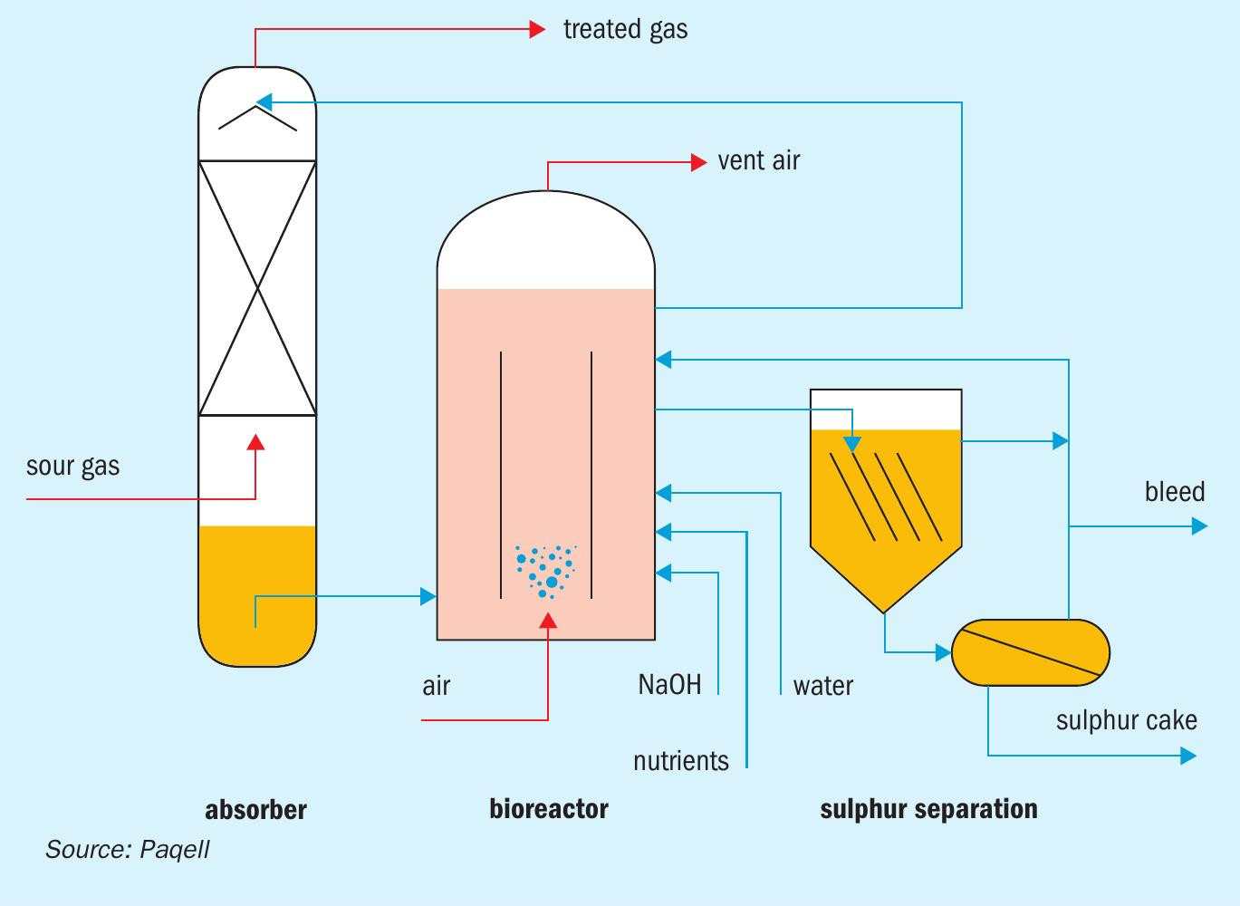
The absorber column is a pressure vessel constructed out of stainless steel. In the absorber, sour gas is counter-currently contacted with lean process solution coming from the bioreactor. The mildly alkaline solution (pH 8 to 9.5, project depending) removes practically all H2S. Due to the alkalinity of the process solution, H2S is converted into soluble bisulphide (HS–). The treated gas exits the absorber from the top of the column. The sulphide rich solution is collected in the sump of the absorber, from where it is routed to the bioreactor, an atmospheric tank constructed out of glass reinforced plastic (GRP).
In the bioreactor the biocatalyst converts the dissolved sulphide into elemental sulphur using oxygen, thereby regenerating the process solution. Air is sparged into the bioreactor for the supply of oxygen. The biocatalyst consists of naturally occurring haloalkaliphilic sulphur oxidising bacteria (Fig. 3). These organisms are not genetically manipulated or modified. The bacteria gain metabolic energy for growth (i.e. reproduction) from the oxidation of H2S and use CO2 as their sole carbon source. The biocatalyst is fast growing and highly resistant and adaptive to varying process conditions. The regenerated solvent is recycled from the bioreactor back to the absorber.

The formed hydrophilic elemental sulphur particles are suspended in the process solution. These are removed from the circulating solution in the sulphur separation section, which typically consists of a settler and/or decanter-centrifuge.
The elemental sulphur has a purity of ~95-98% on dry basis.
The TOG process has the following performance features:
- applicable to sour feed gases with H2S concentrations ranging from 50 ppmv to 100 vol-%;
- H2S removal efficiencies of >99.9%;
- suitable for high range of H2S:CO2 ratios (down to 1:100);
- simple process configuration and control with stable operation;
- low operating and chemical costs;
- no use of environmentally unfriendly chemicals – no hazardous waste streams;
- attractive capex;
- wide and flexible operating range;
- bacteria produce hydrophilic non-sticky sulphur – prevents plugging;
- environmentally friendly process based on a naturally occurring biocatalyst;
- biocatalyst reproduces by itself; after initial fill, no refills are needed;
- inherently safe operation – no concentrated H2S stream created.
Engineering and construction for licensed TOG systems can be provided by several sub-licensing engineering companies, including Fluor.
The produced sulphur can be used as raw material for agricultural applications such as fertilizer or fungicide. Produced sulphur is considered as organic. Several brands of bio sulphur-based suspension concentrates are marketed. Other options include melting the produced sulphur to obtain the Claus sulphur purity specification.
The bleed water stream from the TOG section is water with sodium salts, biomass and elemental sulphur. The pH of this stream is the same as the lean process solution (8 to 9.5 for this project). Depending on the location facilities this stream can be sent to the existing site wastewater treatment; otherwise a separate (biological) water treatment unit needs to be installed or the bleed water needs to be sent offsite for disposal.
TOG optimisation options
There are several optimisation options available for the TOG biological treating system.
Opex reduction: At a sulphur load as in this example, the addition of a sulphidic bioreactor called a ‘selector’ can be considered (TOG ULTRA) that results in a significant reduction in the caustic consumption and bleed water stream formation. In the selector, the sulphide oxidising bacteria are exposed to high concentrations of sulphide. This promotes the growth of sulphur producing microorganisms that tolerate high sulphide concentration and suppresses the growth of sulphate producing micro-organisms for which high sulphide concentrations are toxic.
Feed and product flexibility: Another additional process step that appears attractive to some locations is the conversion of the Thiopaq sulphur product into a product that meets the Claus sulphur purity requirements.
Vent gas stream co-processing can be easily handled in the TOG system despite unfavourable H2S to CO2 ratio.
Although not applicable for this project design basis, TOG systems could provide an advantage when refineries convert to processing biofuels, which typically create sour gas streams with a very unfavourable H2S to CO2 ratio for SRU treatment. The biofuels sour gas stream can bypass the SRU and be directed to the TOG system for processing.
Amine technology
The amine TGT section consists of the amine contactor (amine absorber), amine regeneration system, and amine filtration section (see Fig. 1). The amine contactor is the key equipment item for meeting the stack emissions; any untreated H2 S in the overhead from the amine contactor will be converted to SO2 in the thermal oxidiser stack, along with any COS and CS2 that passes through the hydrogenation section. Sour gas enters near the bottom of the amine contactor and is contacted counter-currently with lean amine solution. H2S is preferentially absorbed into the lean amine solution, with un-desired co-absorption of some CO2.
Generic MDEA is the most widely used, inexpensive chemical solvent suitable for selective H2S removal at low pressure. MDEA has become more widely used than DIPA for refinery and gas plant amine treatment units and for SRU tail gas treating. MDEA provides lower operational costs than DIPA, MEA or DEA, because MDEA requires lower stripping duty per unit of circulation. Lower stripping duty also decreases regenerator overhead condenser duty.
Most specialty solvents are MDEA based, with additives to increase H2S selectivity (decreased CO2 co-absorption).
Common proprietary solvents for selective H2S removal are listed below:
- BASF OASE® Yellow;
- Dow UCARSOL™ HS-101 and HS-103;
- INEOS GAS/SPEC™ TG-10;
- ExxonMobil/BASF FLEXSORB™ SE Plus. This is used for sites with tight H2S removal specifications where the absorber operating temperature is high;
- ExxonMobil/BASF OASE® SULFEXX™ . This is used for sites with tight H2 S removal specifications where the absorber operating temperature is high.
The selectivity of the solvent is important because any CO2 co-absorbed into the rich amine solution will pass into the regenerator overhead and into the TGT acid gas recycle and be routed to the front of the SRU for further processing. This recycling allows increased conversion of sulphur than can be achieved in the Claus section. However, the TGT acid gas recycle stream increases the volumetric throughput across all the Claus, common, and TGT equipment (entire process gas path). Thus, solvents with higher selectivity for H2S decrease the TGT acid gas recycle stream, improving the hydraulic profile through the entire process gas path (Claus SRU, common hydrogenation section and amine TGT section equipment).
Specialty solvent has higher fill and makeup costs compared to generic MDEA, but generic MDEA typically requires higher circulation rate, and often cannot achieve the desired contactor overhead H2S specification. As overall stack SO2 emission specifications become increasing stringent, higher removal of H2S in the amine contactor is required, especially when considering that essentially all of any COS and CS2 present will pass through the contactor untreated.
Oxygen-enrichment technology
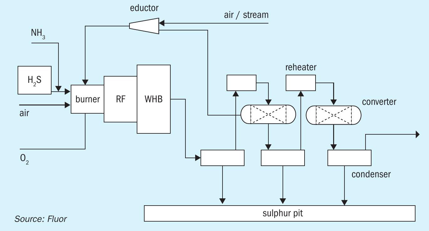
Fluor’s COPE® II Oxygen Enrichment technology was selected to increase each SRU train capacity to 150 t/d, essentially providing the equivalent redundancy of a spare train. Capacity refers to the nominal sulphur content in the combined acid gases. For the purposes of this article, the produced sulphur (Claus SRE) is fixed at 95% of the sulphur contained in the feed acid gases. Fig. 4 shows a process schematic of the COPE® II process.
Oxygen enrichment provides the following major advantages:
- Increases amine acid gas and sour water stripper acid gas processing capability in each train. This could be used for increasing the overall plant processing capability to handle future expansions in upstream refinery units. For this project, pre-investment for future expansions was considered, but not implemented. The overall SRU capacity is fixed at 300 t/d, either by operating three trains at 100 t/d each using only combustion air, or by operating two trains at 150 t/d each using oxygen enrichment. In this manner, the oxygen-enrichment design provides spare capacity while avoiding the need for constructing a fourth SRU train.
- Achieves a higher temperature in the thermal reaction furnace, which enhances destruction of ammonia, hydrocarbons and BTEX in the feed gases. Higher temperature in the thermal reaction furnace also could allow processing of weaker acid gases with higher CO2 content such as is required for many gas plants and gasification system acid gases. For this project, ammonia is present in the SWS off-gas, which has a typical composition with about 35 to 40 mol-% for each of H2 S and NH3 . The amine acid gas contains about 90 to 93 mol-% H2 S, which is within a typical range for refinery amine acid gas streams.
- In addition, many sites report smoother, more reliable and flexible operation when using oxygen enrichment as well as slightly enhanced Claus sulphur recovery efficiency.
For oxygen enrichment, the total O2 required for combustion is supplied by a combination of high-purity oxygen (at least 90 vol-% O2 content) and air from the combustion air blower. Variation in the relative amounts of these sources provides enriched air to the burner, which contains from ~21 vol-% (no enrichment or air-only operation) up to 100 vol-% O2 blown systems. For H2 S-rich refinery acid gas streams, it is not necessary to use high-level oxygen enrichment that might be considered for treating weak acid gases from gas plants or gasification plants.
In COPE® II operation, high-purity oxygen is introduced to the burner separately, partially substituting for air to provide O2 for combustion. This can produce a significant decrease in downstream flow rate. The decrease in downstream flow is mostly due to the reduction in nitrogen associated with the combustion air flow that is replaced by the high-purity O2 stream. Reducing the flow rate of nitrogen lowers the pressure drop through the SRU. Consequently, this allows for an increase in the acid gas flow rate processed, with resultant increased produced sulphur capacity.
Combustion with oxygen-enriched air increases the flame temperature in the thermal reaction furnace compared with air-only combustion. If not tempered, the combustion temperature resulting from high oxygen enrichment levels can exceed the limits of the standard refractory lining that protects the carbon steel shell of the main burner (combustion chamber area) and of the thermal reaction furnace.
COPE® II operation allows for higher levels of oxygen enrichment, even for rich acid gases, without exceeding the temperature limits of the standard refractory linings by recycling process gas from the outlet of the 1st sulphur condenser, through the COPE® ejector, to the COPE® burner. The recycle gas flow rate is controlled to moderate the thermal reaction furnace operating temperature. The COPE® ejector uses motive steam; this steam enters the process, also contributing to the attemperation.
For this project, the normal oxygen enrichment level at expanded 150 t/d sulphur capacity per train can be achieving using medium level oxygen enrichment at about 50 mol-% percent oxygen enrichment.
Thermal oxidiser section
The thermal oxidiser section is the same process scheme for both options.
Treated process gas from either the TOG absorber or from the amine contactor overhead is routed to the thermal oxidisers, where essentially all sulphur species are incinerated to SO2 at 649°C with 2 mol-% excess oxygen prior to release from the stack at safe location.
In the existing facilities, each of the existing SRU trains has a dedicated natural-draft thermal oxidiser. As part of the upgrade, these must be converted to forced-draft thermal oxidisers with low NOx burners. Due to plot limitations, the new thermal oxidisers, associated stacks and associated new air blowers will be located on an adjacent plot area.
Comparison of capex and opex
Fluor prepared an AACE Class 4 estimate (Equipment Factored) based on construction in the US Gulf Coast, 3rd Quarter 2023. Major assumptions include:
- each tail gas treating system is part of an existing larger plant (refinery);
- equipment common for both TGT systems is not included in either cost estimate;
- supply of power and utilities are available from the balance of the plant at the SRU/tail gas treating unit battery limit.
Total installed cost for the Thiopaq O&G TGT case is estimated as $28.5 million. Total installed cost for the amine TGT is estimated as $27.3 million.
The estimated annual opex for the Thiopaq O&G TGT case is estimated as $1.39 million. The estimated annual opex for the amine TGT case is estimated as $1.58 million.
The two options are comparable in terms of both capex and opex.
Discussion and conclusions
Both TOG and amine TGT processes are capable of achieving an environmental emission specification below 300 mg SO2/Nm3, emissions lower than the World Bank Standards for SRU facilities. The relative estimated capex is comparable between the two options for this project basis. The relative opex is also comparable between the two options. The opex for TOG could be reduced if the TOG Ultra design is utilised.
Both options allow for flexible operation and can handle the range of operation between the SRU air case and SRU oxygen enrichment case.
Both options provide safe and reliable tail gas treating. TOG provides better robustness against SO2 breakthrough events.
Although the equipment services count is similar between the options, TOG systems have slightly fewer equipment services to maintain and operate compared with conventional amine technology. The options are comparable in terms of simplicity of operation, with very few equipment items that require frequent maintenance. Comparable operator attention is required for monitoring operation of the two options.
The amine TGT requires greater plot space and more infrastructure for pipe racks and underground drainage facilities.
TOG reduces the load on the Claus, both in terms of sulphur load and gas load (due to absence of amine TGT recycle loop). During oxygen enrichment, somewhat lower supply of high purity oxygen is required in the SRU if a TOG TGT is used, because there is no recycle flow. During future capacity expansions, the advantage TOG provides in terms of debottlenecked SRU processing capacity may be significant.
Moreover, the TOG system can be designed to handle additional other refinery streams with unfavourable H2 S/CO2 ratios, resulting in reduction of Claus load, reduction in fuel gas consumption from co-firing, and/or lowered oxygen enrichment level.
As another consideration, the client’s image can be enhanced by selecting TOG because it is an intrinsically safe and environmentally conscious process. Other intangibles, such as avoiding the carbon emissions associated with the manufacturing of amine solvent, may also influence the client’s decision in favour of TOG.
In conclusion, using Thiopaq O&G for tail gas treating provides a cost effective and attractive alternative to more traditional amine TGT. This is especially true for this project, where the client wishes to act as an environmentally friendly company.